MERCEDES-BENZ G-Class 2017 W463 Owner's Manual
Manufacturer: MERCEDES-BENZ, Model Year: 2017, Model line: G-Class, Model: MERCEDES-BENZ G-Class 2017 W463Pages: 286, PDF Size: 4.91 MB
Page 211 of 286
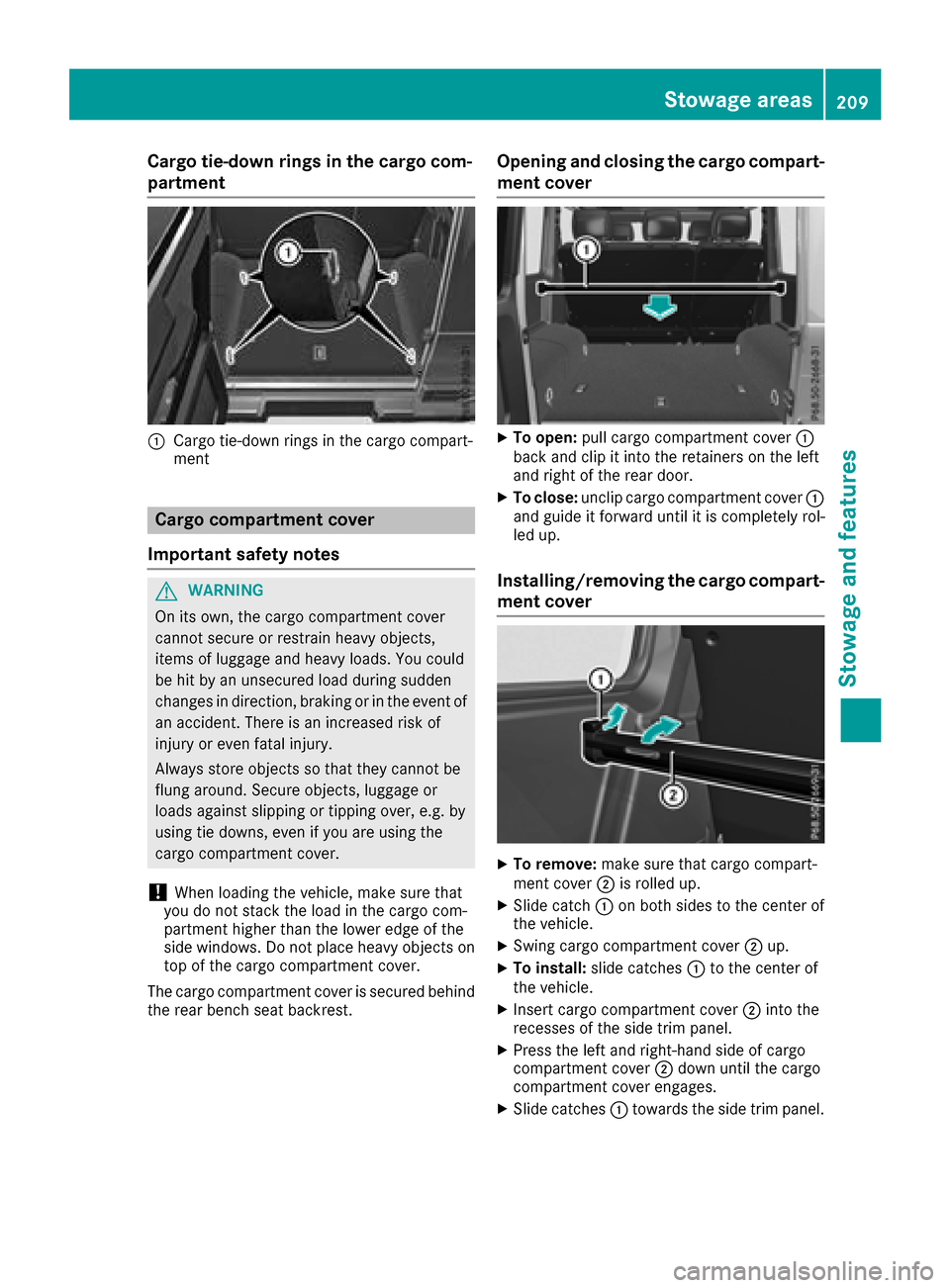
Cargo tie-down rings in thecargo com-
partment
:Cargo tie-down rings in th ecargo compart-
ment
Cargo compartment cover
Important safety notes
GWARNING
On its own,t hecargo compartmen tcover
canno tsecure or restrain heavyo bjects,
items of luggagea nd heavyloads.You could
be hit by an unsecured load durin gsudden
changes in direction,b raking or in theevent of
an accident. Thereisani ncreased riskof
injury or eve nfatal injury.
Always store object ssothatthe yc anno tbe
flun garound. Secure objects, luggageo r
loads against slipping or tippingo ver, e.g.by
usingt ie downs, evenify ou are usingthe
cargo compartmen tcover.
!When loadingt hevehicle ,makes ure that
you do no tstack th eload in th ecargo com-
partmen thigher than th elower edge of the
side windows. Do no tplaceh eavyo bjectson
to poft hecargo compartmen tcover.
The cargo compartmen tcover is secured behind
th er ear bench seat backrest.
Opening and closing th ecargo compart-
men tcover
XTo open: pull cargo compartmen tcover :
back and clip it int othe retainers on th eleft
and righ toftherear door.
XTo close: unclip cargo compartmen tcover :
and guide it forward until it is completely rol-
led up.
Installing/removing th ecargo compart-
men tcover
XTo remove: makesure that cargo compart-
men tcover ;is rolled up.
XSlid ecatch :on boths ides to th ecente rof
th ev ehicle.
XSwin gcargo compartmen tcover ;up.
XTo install: slide catches :to th ecente rof
th ev ehicle.
XInsertc argo compartmen tcover ;intot he
recesses of th eside trim panel.
XPress th eleft and right-hands ide of cargo
compartmen tcover ;down until th ecargo
compartmen tcover engages.
XSlid ecatches :towards th eside trim panel.
Stowage areas209
Stowage and features
Z
Page 212 of 286
Features
Cup holder
Important safety notes
GWARNIN G
If you transpor tobject sinthevehicl einterio r
and these are no tadequately secured ,the y
could slip or be flun garoun dand thereby
strik evehicl eoccupants. In addition ,cup
holders ,open stowage spaces and mobile
phon ebrackets may no talways be able to
hold th eobject splaced in them in th eevent of
an accident. Ther eisariskofi njury, particu-
larly in th eevent of shar pbraking or sudde n
changes of direction .
RAlways stow objectsinsuchaw ay that they
canno tbetosseda bout in these or similar
situations.
RAlways mak esure that object sdonotpro -
trude out of th estowage spaces, luggag e
nets or stowage nets .
REnsure that closable stowage spaces are
shut before beginning your journey.
RAlways stow and secure heavy, hard ,poin -
ted, sharp-edged, fragile or larg eobject sin
th ec argo compartment.
!Only use th ecup holders for containers of
th er ight siz eand whic hhave lids. The drinks
could otherwise spill .
Observ ethe loadin gguidelines (
Ypage 204).
Cup holder on th ecenter console
XFold cup holder :all th eway up.
Cup holders in th erearc ompartment
!Ensure that you remove all containers from
th ec up holder in th erear before foldin gthe
seat backrest and th eseat cushion of th erear
bench seat forwards .
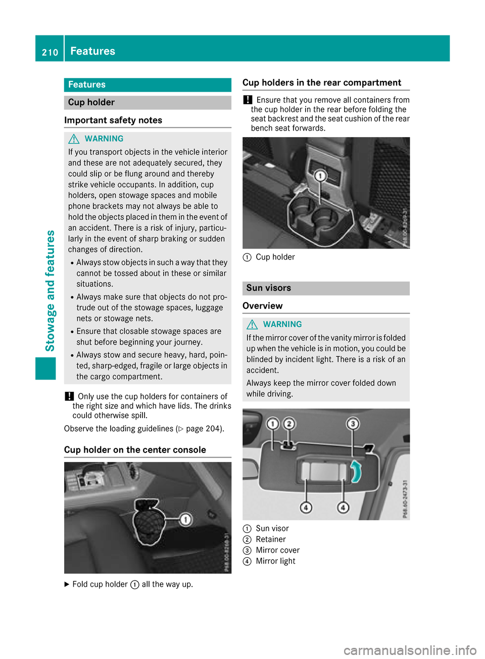
:Cup holder
Sun visors
Overview
GWARNIN G
If th emirror cover of th evanit ymirror is folded
up when th evehicl eisinm otion,you could be
blinded by inciden tlight. Ther eisariskofa n
accident.
Always keep th emirror cover folded down
while driving .
:Sun visor
;Retainer
=Mirror cover
?Mirror ligh t
210Features
Stowage and features
Page 213 of 286
Vanity mirrorinthe sun visor
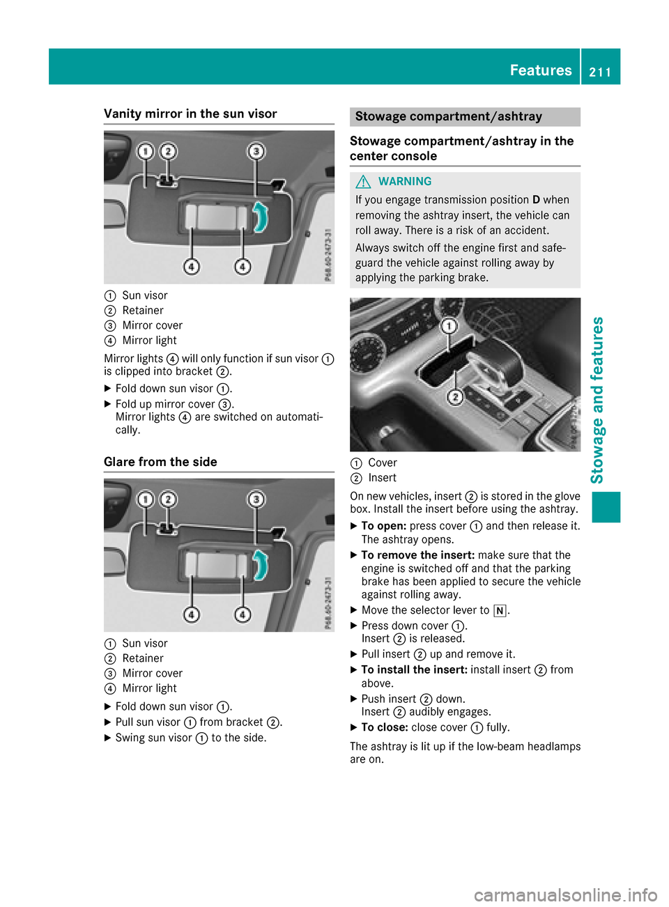
:Sun visor
;Retainer
=Mirror cover
?Mirror light
Mirror lights ?will onlyf unctionifsunvisor :
is clipped into bracket ;.
XFolddowns un visor :.
XFoldupm irror cover =.
Mirror lights ?are switched on automati-
cally.
Glare from the side
:Sun visor
;Retainer
=Mirror cover
?Mirror light
XFoldd owns un visor :.
XPull sunv isor:from bracket ;.
XSwing sunvisor:to the side.
Stowage compartment/ashtray
Stowage compartment/ashtray in the
centerc onsole
GWARNING
If yo uengage transmission position Dwhen
removing the ashtrayi nsert, the vehiclecan
rolla way. There is ariskofana ccident.
Alway sswitch off the engine first and safe-
guard the vehicl eagain st rolling away by
applying the parking brake.
:Cover
;Insert
On new vehicles, insert ;is stored in the glove
box. Install the insert before using the ashtray.
XTo open: press cover :and then release it.
The ashtrayo pens.
XTo remove the insert: make sure thatthe
engine is switched off and thatt he parking
brake hasb eena pplied to secure the vehicle
against rolling away.
XMov ethe selecto rlev er to i.
XPress down cover :.
Insert ;is released.
XPull insert ;up and remove it.
XTo installt he insert:installinsert ;from
above.
XPush insert ;down.
Insert ;audibl yengages.
XTo close: close cover :fully.
The ashtrayisl itup if the low-bea mheadlamps
are on.
Features211
Stowag eand featur es
Z
Page 214 of 286
Ashtrayint herea rcom partment
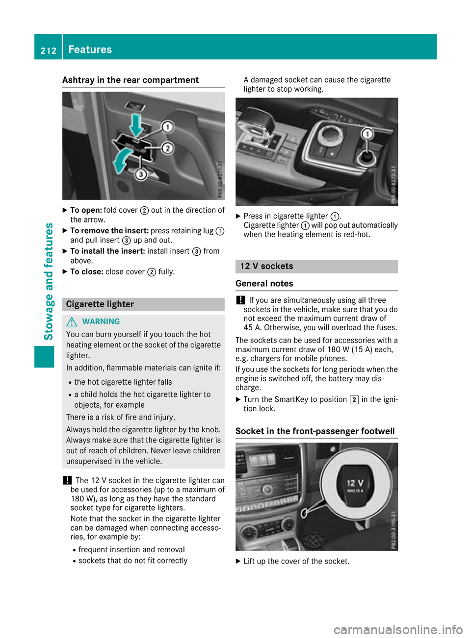
XTo open :fol dc over ; out in th edirection of
th ea rrow.
XTo remove th einsert: press retaining lug :
and pull insert =up and out .
XTo install th einsert: installinsert =from
above.
XTo close: close cover ;fully.
Cigarette lighter
GWARNIN G
You can burn yourself if you touch th ehot
heating elemen torthesocke tofthecigarette
lighter.
In addition ,flammabl ematerials can ignit eif:
Rtheh ot cigarette lighte rfall s
Rac hild hold sthe hot cigarette lighte rto
objects ,for exampl e
There is ariskoff irea nd injury.
Always hold th ecigarette lighte rbytheknob.
Always mak esuret hatthe cigarette lighte ris
out of reac hofchildren .Never leav echildren
unsupervised in th evehicle.
!The 12 Vsocke tinthecigarette lighte rcan
be used for accessories (up to amaximum of
18 0W ), as lon gastheyh avet he standard
socke ttyp ef or cigarette lighters.
Not ethatthe socke tinthecigarette lighte r
can be damaged when connecting accesso-
ries, for exampl eby:
Rfrequen tinsertion and removal
Rsockets that do no tfit correctl y Ad
amaged socke tcan caus ethe cigarette
lighte rtostopw orking .
XPress in cigarette lighte r:.
Cigarette lighte r: will pop out automatically
when th eheating elemen tisred-hot .
12Vsocke ts
Gene raln otes
!If you are simultaneously usin gall three
sockets in th evehicle, mak esuret hatyou do
no te xcee dthe maximum curren tdraw of
45 A. Otherwise ,you will overload th efuses.
The sockets can be used for accessories wit ha
maximum curren tdraw of 18 0W(15 A) each,
e.g. chargers for mobile phones.
If you use th esockets for lon gperiods when th e
engin eisswitched off ,the battery may dis-
charge .
XTurn th eSmartKey to position 2in th eigni-
tion lock.
Socket in th efront-passenger footwell
XLiftupt hecover of th esocket.
212Features
Stowage and features
Page 215 of 286
The cigarettelighter socket can be also used
(Ypage 212). This is the case even if the Smart-
Key has been removed from the ignition lock.
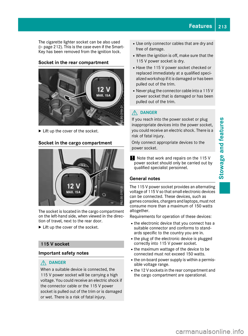
Socket in the rear compartment
XLift up the cover of the socket.
Socket in the cargo compartment
The socket is located in the cargo compartment
on the left-hand side, when viewed in the direc-
tion of travel, next to the rear door.
XLift up the cover of the socket.
115 Vsocket
Important safety notes
GDANGER
When asuitable device is connected, the
115 Vpower socket will be carrying ahigh
voltage. You could receive an electric shock if the connector cable or the 115 Vpower
socket is pulled out of the trim or is damaged
or wet. There is arisk of fatal injury.
RUse only connector cables that are dry and
free of damage.
RWhen the ignition is off, make sure that the
115 Vpower socket is dry.
RHave the 115 Vpower socket checked or
replaced immediately at aqualified speci-
alized workshop if it is damaged or has been
pulled out of the trim.
RNever plug the connector cable into a115 V
power socket that is damaged or has been
pulled out of the trim.
GDANGER
If you reach into the power socket or plug
inappropriate devices into the power socket,
you could receive an electric shock.T here is a
risk of fatal injury.
Only connect appropriate devices to the
power socket.
!Note that work and repairs on the 115 V
power socket should only be carried out by
qualified specialist personnel.
General notes
The 115 Vpower socket provides an alternating
voltage of 115 Vsothat small electronic devices
can be connected. These devices, such as
games consoles, chargers and laptops, must not consume more than amaximum of 150 watts
altogether.
Requirements for operation of these devices:
Rthe electronic device that you connect has a
suitable connector and conforms to stand-
ards specific to the country you are in.
Rthe plug of the electronic device is plugged
correctly into 115 Vpower socket.
Rthe maximum wattage of the device to be
connected must not exceed 150 watts.
Rthe on-board power supply is within apermis-
sible voltage range.
Rthe 12 Vsocketsint he rear compartment and
the cargo compartment are operational.
Features213
Stowage and features
Z
Page 216 of 286
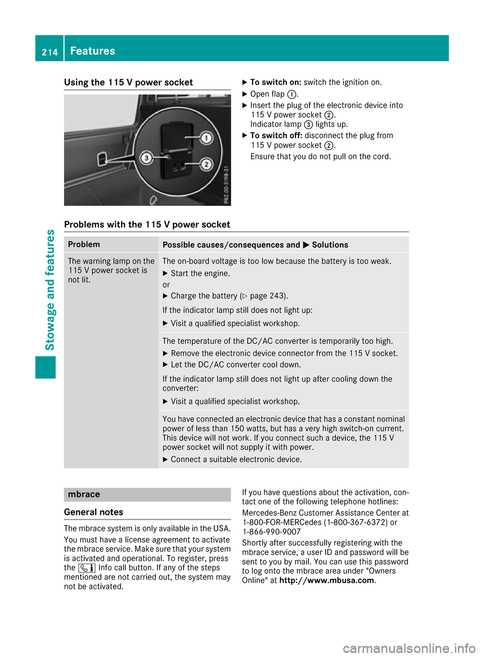
Using the 115Vpower socketXTo switch on: switchthe ignition on.
XOpen flap :.
XInsert the plug of the electronic device into
115Vpower socket ;.
Indicator lamp =lights up.
XTo switch off: disconnectthe plug from
115 Vpower socket ;.
Ensure that you do not pull on the cord.
Problem swith the 115 Vpower socket
ProblemPossible causes/consequences and MSolutions
The warninglamp on the
115 Vpower socket is
not lit.The on-board voltage is too low because the battery is too weak.
XStart the engine.
or
XCharge the battery (Ypage 243).
If the indicator lamp still does not light up:
XVisit aqualified specialist workshop.
The temperature of the DC/A Cconverter is temporarily too high.
XRemove the electronic device connector from the 115 Vsocket.
XLet the DC/A Cconverter cool down.
If the indicator lamp still does not light up after coolingd own the
converter:
XVisit aqualified specialist workshop.
You have connected an electronic device that has aconstan tnominal
power of less than 150 watts, but has avery high switch-on current.
This device will not work. If you connec tsuch adevice, the 115 V
power socket will not supply it with power.
XConnect asuitable electronic device.
mbrace
Genera lnotes
The mbrace system is only available in the USA.
You must have alicens eagreementtoa ctivate
the mbrace service. Make sure that your system
is activated and operational. To register, press
the ï Infoc all button. If any of the steps
mentioned are not carried out, the system may
not be activated. If you have question
sabout the activation ,con-
tact one of the following telephon ehotlines:
Mercedes-Benz Customer Assistance Center at 1-800-FOR-MERCedes (1-800-367-6372) or
1-866-990-9007
Shortly after successfully registering with the
mbrace service, auser ID and password will be
sent to you by mail. You can use this password
to log ont othe mbrace area under "Owners
Online" at http://www.mbusa.com.
214Features
Stowage and features
Page 217 of 286
The system is availableif:
Rit has been activated and is operational
Rthe corresponding mobile phone network is
availablefor transmitting data to the Cus-
tomer Center
Ras ervice subscription is available
Determining the location of the vehicle on amap
is only possible if:
RGPS reception is available
Rthe vehicle position can be forwarded to the
Customer Assistance Center
The mbrace system
To adjust the volume during acall, proceed as
follows:
XPress the WorX button on the multi-
function steerin gwheel.
or
XUse the multimedia system volume control.
The system offers various services, e.g.:
RAutomatic and manual emergencyc all
RRoadside Assistance call
RInfo call
You can find information and adescription of all
availablef eatures under "Owners Online" at
http://www.mbusa.com.
System self-test
After you have switched on the ignition, the sys- tem carries out aself-diagnosis.
Am alfunction in the system has been detected
if one of the following occurs:
RThe indicator lamp in the SOS button does not come on during the system self-test.
RThe indicator lamp in the FRoadside
Assistance button does not light up during
self-diagnosis of the system.
RThe indicator lamp in the ïInfo call button
does not light up during the system self-diag-
nosis
RThe indicator lamp in one or more of the fol-
lowing button scontinues to light up red after
the system self-diagnosis:
-SOS button
-F Roadside Assistance call button
-Info call button ï
Rafter the system self-diagnosis, the Inoper‐ativeorServiceNotActivatedmessage
appears in the multifunction display.
If am alfunction is indicated as outlined above,
the system may not operate as expected. In the
event of an emergency, help will have to be
summoned by other means.
Have the system checked at the nearest
Mercedes-Benz ServiceC enter or contact the
following service hotlines:
Mercedes-Benz Customer Assistance Center at
1-800-FOR-MERCedes (1-800-367-6372)o r
1-866-990-9007
Emergency call
Important safety notes
GWARNING
It can be dangerous to remain in the vehicle,
even if you have pressed the SOS button in an emergencyi f:
Ryou see smoke inside or outside of the vehi-
cle, e.g. if there is afire after an accident
Rthe vehicle is on adangerous section of
road
Rthe vehicle is not visible or cannot easily be seen by other road users, particularly when
dark or in poor visibility conditions
There is arisk of an accident and injury.
Leave the vehicle immediately in this or simi-
lar situations as soon as it is safe to do so.
Move to asafe location along with other vehi-
cle occupants. In such situations, secure the
vehicle in accordanc ewith national regula-
tions, e. g. with awarning triangle.
General notes
Observe the notes on system activation
(Ypage 214).
An emergencyc all is dialed automatically if an
air bag or Emergency Tensionin gDevice is trig-
Features215
Stowage and features
Z
Page 218 of 286
gered. You cannot end an automatically trig-
gered emergencycall yourself.
An emergencyc all can also be initiated man-
ually.
As soon as the emergencyc all has been initi-
ated, the indicator lamp in the SOS button
flashes. The Connecting Call
message
appears in the multifunction display.
The audio output is muted.
Once the connection has been made, the Call
Connectedmessage appears in the multifunc-
tion display.
All important information on the emergencyi s
transmitted, for example:
RCurrent location of the vehicle (as determined
by the GPS system)
RVehicle identification number
RInformation on the severity of the accident
Shortly after the emergencyc all has been initi-
ated, avoice connection is automatically estab-
lished between the Customer Assistance Center
and the vehicle occupants.
RIf the vehicle occupantsr espond, the
Mercedes-Benz Customer Assistance Center
attempt stoget more information on the
emergency.
Rif there is no response from the vehicle occu-
pants, an ambulance is immediately sent to
the vehicle.
If no voice connection can be established to the
Mercedes-Benz Customer Assistance Center,
the system has been unable to initiate an emer-
gency call.
This can occur, for example, if the relevant
mobile phone network is not available. The indi-
cator lamp in the SOS button flashes continu-
ously.
The Call Failed
message appears in the mul-
tifunction display and must be confirmed.
In this case, summon assistance by other
means.
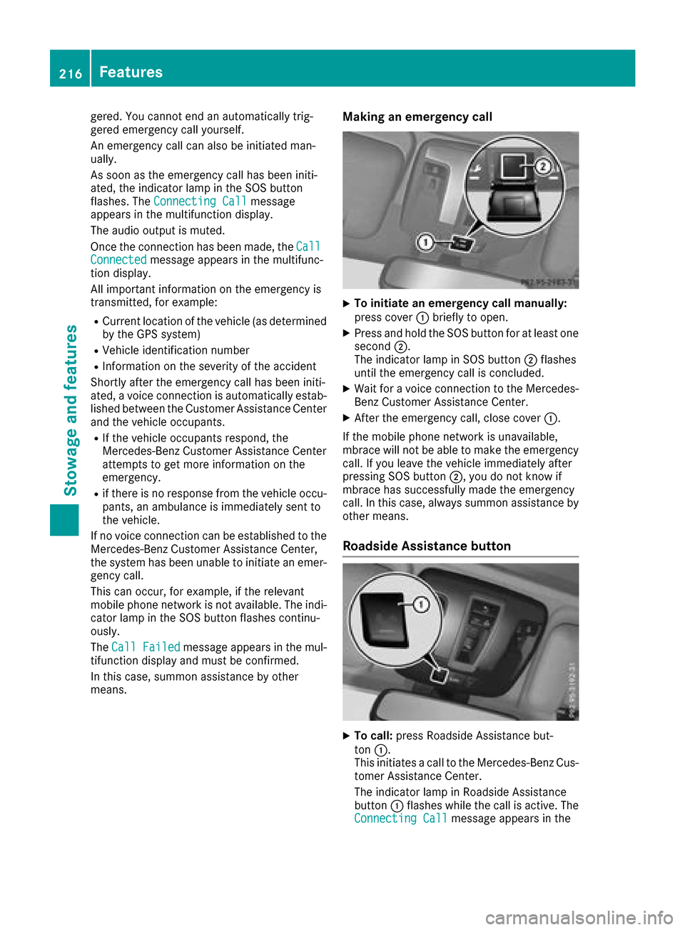
Making an emergency call
XTo initiate an emergency call manually:
press cover :briefly to open.
XPress and hold the SOS button for at least one
second ;.
The indicator lamp in SOS button ;flashes
until the emergencyc all is concluded.
XWait foravoice connection to the Mercedes-
Benz Customer Assistance Center.
XAfter the emergencyc all, close cover:.
If the mobile phone network is unavailable,
mbrace will not be able to make the emergency
call. If you leave the vehicle immediately after
pressing SOS button ;,you do not know if
mbrace has successfully made the emergency
call. In this case, always summon assistance by
other means.
RoadsideA ssistance button
XTo call:press Roadside Assistance but-
ton :.
This initiates acall to the Mercedes-Benz Cus-
tomer Assistance Center.
The indicator lamp in Roadside Assistance
button :flashes while the call is active. The
Connecting Call
message appears in the
216Features
Stowage and features
Page 219 of 286
multifunction display.The audio outpu tis
muted.
If ac onnection can be made ,the Call
Connec‐tedmessage appears in the multifunction dis-
play.
If am obilep hone network and GPS reception
are available, the system transfers data to the
Mercedes-Benz Customer Assistance Center,
for example:
Rcurrent location of the vehicle
Rvehiclei dentification number
The multimedia system display indicates that a
call is active. During the call ,you can change to
the navigation menu by pressing the NAVI but-
ton on the multimedia system, for example.
Voice outpu tisnot available in this case.
Av oice connection is established betweent he
Mercedes-Benz Customer Assistance Center
and the vehicleo ccupants.
From the remote malfunction diagnosis, the
Mercedes-Benz Customer Assistance Center
can ascertai nthe nature of the problem
(
Ypage 220).
The Mercedes-Benz Customer Assistance Cen-
ter either sends aqualified Mercedes-Benz tech-
nician or makes arrangements for you rvehicle
to be transported to the nearest Mercedes-Benz Service Center.
You may be charged for services such as repair
work and/or towing.
You can find more informatio ninthe separate
mbrace manual.
The system has not been abletoi nitiateaRoad-
side Assistance call ,if:
Rthe F indicator lamp for the Roadside
Assistance call button is flashing continu-
ously.
Rno voice connection to the Mercedes-Benz
Customer Assistance Center was estab-
lished.
This can occur if the relevant mobilep hone net-
work is not available, for example.
The Call Failed
message appears in the mul-
tifunction display.
XTo end acall: press the ~button on the
multifunction steering wheel.
or
XPress the corresponding multimedia system
button for ending aphone call.
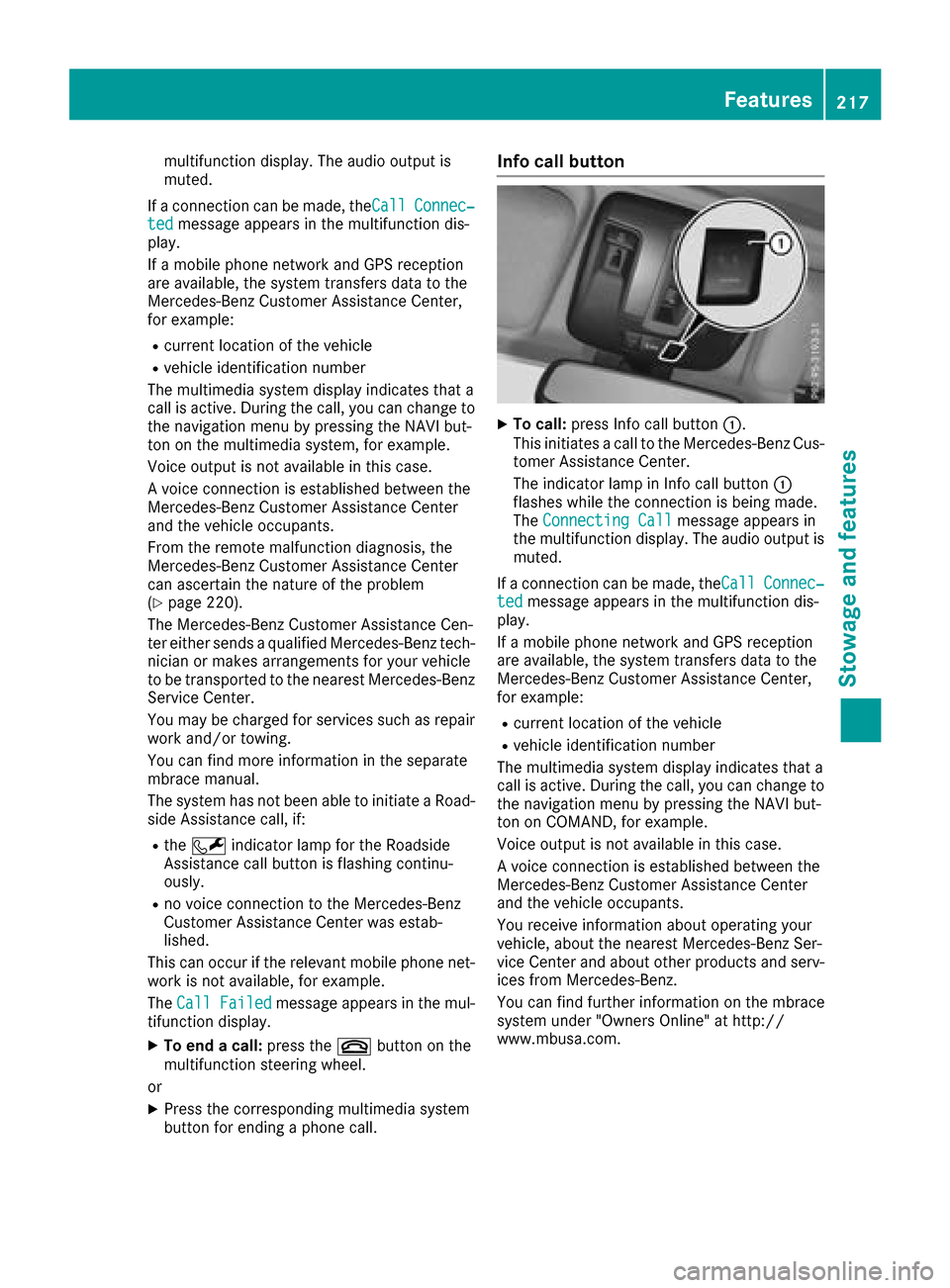
Info call button
XTo call: press Info call button :.
This initiates acall to the Mercedes-Benz Cus-
tomer Assistance Center.
The indicator lamp in Info call button :
flashes whilet he connection is being made.
The ConnectingC all
message appears in
the multifunction display .The audio outpu tis
muted.
If ac onnection can be made ,the Call
Connec‐tedmessage appears in the multifunction dis-
play.
If am obilep hone network and GPS reception
are available, the system transfers data to the
Mercedes-Benz Customer Assistance Center,
for example:
Rcurrent location of the vehicle
Rvehiclei dentification number
The multimedia system display indicates that a
call is active. During the call ,you can change to
the navigation menu by pressing the NAVI but-
ton on COMAND, for example.
Voice outpu tisnot available in this case.
Av oice connection is established betweent he
Mercedes-Benz Customer Assistance Center
and the vehicleo ccupants.
You receive informatio nabou toperating your
vehicle, aboutt he nearest Mercedes-Benz Ser-
vice Center and abouto ther products and serv-
ices from Mercedes-Benz.
You can find further informatio nonthe mbrace
system under "Owners Online" at http://
www.mbusa.com.
Features217
Stowage and features
Z
Page 220 of 286
The system has not been able to initiate an MB
Info call, if:
Rthe indicator lamp in theïInfo call button
is flashing continuously.
Rno voice connection to the Mercedes-Benz
Customer Assistance Center was estab-
lished.
This can occur if the relevant mobile phone net-
work is not available, for example.
The Call Failed
message appears in the mul-
tifunction display.
XTo end acall: press the ~button on the
multifunction steerin gwheel.
or
XPress the corresponding multimedia system
button for ending aphone call.
Call priority
When service calls are active, e.g. Roadside
Assistance or Info calls, an emergencyc all can
still be initiated. In this case, an emergencyc all
will take priority and override all other active
calls.
The indicator lamp of the respective button
flashes until the call is ended.
An emergencyc all can only be terminated by the
Mercedes-Benz Customer Assistance Center.
All other calls can be ended by pressing:
Rthe ~ button on the multifunction steering
wheel
Rthe corresponding button in the multimedia
system to end the voice call
When acall is initiated, the audio system is
muted.
The mobile phone is no longer connected to the multimedia system.
However, if you want to use your mobile phone,
do so only when the vehicle is stationary and in
as afe location.
Downloading destinations
Downloading destinations
Downloading destinations gives you access to a
database with over 15 million points of interest
(POIs). These can be downloaded on the navi-
gation system in your vehicle. If you know the
destination, the address can be downloaded.
Alternatively, you can obtain the location of Points of Interest (POIs)/important destinations
in the vicinity.
Furthermore, you can download routes with up
to four way points.
You are prompted to confirm route guidance to
the address entered.
XSelect Yesby turning 3or sliding 1
the controller and confirm with 7.
The system calculates the route and subse-
quently start sthe route guidance with the
address entered.
If you select No
the address can be stored in
the address book.
The destination download function is available
if:
Rthe vehicle is equipped with anavigation sys-
tem.
Rthe relevant mobile phone network is availa-
ble and data transfer is possible.
Route Assistance
This service is part of the mbrace PLUS Package
and cannot be purchased separately.
You can use the Route Assistance function even
if the vehicle is not equipped with anavigation
system.
Within the framework of this service, you receive
ap rofessional and reliable form of navigation
support without having to leave your vehicle.
The customer service representative finds a
suitable route depending on your vehicle's cur-
rent position and the desired destination. You
will then be guided live through the current route
section.
Search &Send
General notes
To use "Search &Send", your vehicle must be
equipped with mbrace and anavigation system.
Additionally, an mbrace service subscription
must be completed.
"Search &Send" is adestination entr yservice. A
destination address which is found on Google
Maps
®can be transferred via mbrace directly to
your vehicle's navigation system.
218Features
Stowage and features