MERCEDES-BENZ G500 2002 W463 Owner's Manual
Manufacturer: MERCEDES-BENZ, Model Year: 2002, Model line: G500, Model: MERCEDES-BENZ G500 2002 W463Pages: 385, PDF Size: 30.37 MB
Page 321 of 385
318 Tires, Wheels
Te ch n i c a l
data Instruments
and controlsOperation DrivingInstrument
cluster displayPractical hintsCar care Index
Tire inflation pressure
A table (see fuel filler flap) lists the tire inflation
pressures specified for Mercedes-Benz recommended
tires as well as for the varying operating conditions.
Important!
Tire pressure changes by approximately 1.5 psi (0.1 bar)
per 18
°F (10
°C) of air temperature change. Keep this in
mind when checking tire pressure inside a garage –
especially in the winter.
Example:
If garage temperature = approximately +68
°F (+20
°C)
and ambient temperature = approximately +32
°F (0
°C)
then the adjusted air pressure = specified air pressure
+3 psi (+0.2 bar).Tire pressures listed for light loads are minimum values
offering high driving comfort. Increased inflation
pressures for heavy loads produce favorable handling
characteristics with lighter loads and are perfectly
permissible. The ride of the vehicle, however, will
become somewhat harder.
Tire temperature and pressure increase with the vehicle
speed. Tire pressure should therefore only be checked
and corrected on cold tires. Correct tire pressure in
warm tires only if pressure has dropped below the
pressure listed in the table and the respective operating
conditions are taken into consideration.
An underinflated tire due to a slow leak (e.g. due to a
nail in the tire) may cause damage such as tread
separation, bulging etc.. Regular tire pressure checks
(including the spare tire) at intervals of no more than
14 days are therefore essential.
J_G463.book Seite 318 Mittwoch, 19. September 2001 8:06 08
Page 322 of 385
319 Battery
Te ch n i c a l
data Instruments
and controlsOperation DrivingInstrument
cluster displayPractical hintsCar care Index If a tire constantly loses air, it should be inspected for
damage.
The spare tire should be checked periodically for
condition and inflation. Spare tire will age and become
worn over time even if never used, and thus should be
inspected and replaced when necessary.Battery
Important!
Battery replacement information:
The maintenance-free battery is located in front of the
rear seat bench and below the cup holder.
Jump starting terminals are located in the lef t side of the
engine compartment, see page 321.
Wa r n i n g !
Do not overinflate tires. Overinflating tires can
result in sudden deflation (blowout) because they
are more likely to become punctured or damaged
by road debris, potholes etc.. Follow recommended
inflation pressures.Do not overload the tires by exceeding the specified
vehicle capacity weight (as indicated by the label
on the driver’s door latch post). Overloading the
tires can overheat them, possibly causing a
blowout.
Wa r n i n g !
Failure to follow these instructions can result in
severe injury or death.Never lean over batteries while connecting, you
might get injured.Battery fluid contains sulfuric acid. Do not allow
this fluid to come in contact with eyes, skin or
clot hin g. In cas e i t d oes , i mm ed ia tely f lus h a f fected
area with water and seek medical help if necessary.A battery will also produce hydrogen gas, which is
flammable and explosive. Keep flames or sparks
away from battery, avoid improper connection of
jumper cables, smoking etc..
J_G463.book Seite 319 Mittwoch, 19. September 2001 8:06 08
Page 323 of 385
320 Battery
Te ch n i c a l
data Instruments
and controlsOperation DrivingInstrument
cluster displayPractical hintsCar care Index
The service life of the battery is dependent on its
condition of charge. The battery should always be kept
sufficiently charged, in order to last an optimum length
of time.
Therefore, we strongly recommend that you have the
battery charge checked frequently, and corrected if
necessary, especially if you use the vehicle less than
approximately 200 miles (300 km) per month,
mostly for short distance trips, or if it is not used for
long periods of time.
Only charge a battery with a battery charger after the
battery has been disconnected from the vehicle’s
electrical circuit.
Always disconnect the battery negative lead first and
connect last.
When removing and connecting the battery, always
make sure that all electrical consumers are off and the
key is in starter switch position 0. The battery must
always be securely installed when the vehicle is in
operation. During removal and installation always
protect the disconnected battery positive (+) terminal
with the cover attached to the battery.While t he en gin e is run ning t he batter y te rm in al clamp s
must not be loosened or detached, otherwise the
generator and other electronic components would be
damaged.
Note:
The gear selector lever will remain locked in
position “P” and the electronic key can not be turned in
the starter switch, if the vehicle battery is disconnected
or discharged.
After reconnecting the battery also set the clock (see
COMAND operator’s manual), synchronize the
electronic stability program (ESP) (see page 244) and
the front seat head restraints (see page 47).
Battery recycling
Batteries contain material that can harm the
environment with improper disposal.
Large 12 Volt storage batteries contain lead.
Recycling of batteries is the preferred method of
disposal.
Many states require sellers of batteries to accept old
batteries for recycling.
J_G463.book Seite 320 Mittwoch, 19. September 2001 8:06 08
Page 324 of 385
321 Jump starting
Te ch n i c a l
data Instruments
and controlsOperation DrivingInstrument
cluster displayPractical hintsCar care Index Jump startingImportant!
A discharged battery can freeze at approximately +14
°F
(–10
°C). In that case, it must be thawed out before
jumper cables are used. Attempting to jump start a
frozen battery can result in it exploding, causing
personal injury.
Jumper cable specifications:
•Minimum cable cross-section of 25 mm
2 or
approximately 2 AWG
•Maximum length of 11.5 ft. (3.5 m).
If the battery is discharged, the engine should be started
with jumper cables and the (12 V) battery of another
vehicle.
Only use 12 V battery to jump start your vehicle. Jump
starting with more powerful battery could damage the
vehicle’s electrical systems, which will not be covered
by the Mercedes-Benz Limited Warranty.
The battery is located in front of the rear seat bench and
below the cup holder.
Wa r n i n g !
Failure to follow these directions will cause
damage to the electronic components, and can lead
to a battery explosion and severe injury or death.Never lean over batteries while connecting or jump
starting, you might get injured.Battery fluid contains sulfuric acid. Do not allow
this fluid to come in contact with eyes, skin or
clothing. In case it does, immediately flush affected
area with water, and seek medical help if
necessary.A battery will also produce hydrogen gas, which is
flammable and very explosive. Keep flames or
sparks away from battery, avoid improper
connection of jumper cables, smoking etc..Read all instructions before proceeding.
J_G463.book Seite 321 Mittwoch, 19. September 2001 8:06 08
Page 325 of 385
322 Jump starting
Te ch n i c a l
data Instruments
and controlsOperation DrivingInstrument
cluster displayPractical hintsCar care Index
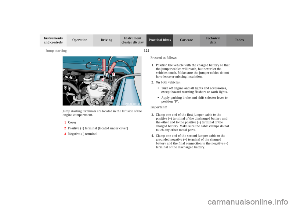
Jump startin g term in als ar e located in t he lef t s id e of t he
engine compartment.
1Cover
2Positive (+) terminal (located under cover)
3Negative (-) terminalProceed as follows:
1. Position the vehicle with the charged battery so that
the jumper cables will reach, but never let the
vehicles touch. Make sure the jumper cables do not
have loose or missing insulation.
2. On both vehicles:
•Turn off engine and all lights and accessories,
except hazard warning flashers or work lights.
•Apply parking brake and shift selector lever to
position “P”.
Important!
3. Clamp one end of the first jumper cable to the
positive (+) terminal of the discharged battery and
the other end to the positive (+) terminal of the
charged battery. Make sure the cable clamps do not
touch any other metal parts.
4. Clamp one end of the second jumper cable to the
grounded negative (–) terminal of the charged
battery and the final connection to the negative (–)
terminal of the discharged battery.
J_G463.book Seite 322 Mittwoch, 19. September 2001 8:06 08
Page 326 of 385
323 Jump starting
Te ch n i c a l
data Instruments
and controlsOperation DrivingInstrument
cluster displayPractical hintsCar care Index Important!
5. Start engine of the vehicle with the charged battery
and run at high idle. Make sure the cables are not
on or near pulleys, fans, or other parts that move
when the engine is started. Allow the discharged
battery to charge for a few minutes. Start engine of
the disabled vehicle in the usual manner.
6. After the engine has started, remove jumper cables
by exactly reversing the above installation
sequence, starting with the last connection made
first. When removing each clamp, make sure that it
does not touch any other metal or the other clamp
while the other end is still attached.Notes:
If engine does not run after several unsuccessful
starting attempts, have it checked at the nearest
authorized Mercedes-Benz Light Truck Center.
Excessive unburned fuel may damage the catalytic
converter.
J_G463.book Seite 323 Mittwoch, 19. September 2001 8:06 08
Page 327 of 385
324 Towing
Te ch n i c a l
data Instruments
and controlsOperation DrivingInstrument
cluster displayPractical hintsCar care Index
Towing the vehicle
Notes:
The selector lever will remain locked in position “P” and
the electronic key cannot be turned in the starter switch
if the battery is disconnected or discharged. See battery
on page 319 or jump starting on page 321.
In order to move the vehicle, shift automatic
transmission to position “N”.
Transmission selector lever, manually unlocking, see
page 327.Important!
When towing the vehicle, please, note the following:
Towing of the vehicle should only be done using the
properly installed towing eye bolt. Never attach tow
cable, tow rope or tow rod to vehicle chassis, frame
or suspension parts.
The vehicle may be towed with all wheels on the
ground and the selector lever in position “N” for
distances up to 30 miles (50 km) and at a speed not
to exceed 30 mph (50 km / h). The key must be in
starter switch position 2.
With the automatic central locking activated and the
engine running, the vehicle doors lock if the left front
wheel is turning at vehicle speeds of approximately
9 mph (15 km / h) or more.
To prevent the vehicle door locks from locking,
deactivate the automatic central locking. See the
individual setting menu “VEHICLE” – “AUTOMATIC
DOOR LOCK” on page 118.
We recommend that the vehicle be transported using
flat bed equipment. This method is preferable to other
types of towing.
To prevent damage during transport, do not tie down
vehicle by its chassis or suspension parts.
Prior to towing the vehicle with all wheels on the
ground, make certain that the electronic key is in
starter switch position 2.If the electronic key is left in the starter switch
position 0 for an extended period of time, it can no
longer be turned in the switch. In this case, the
steering is locked. To unlock, remove electronic key
from starter switch and reinsert.
With the engine not running, there is no power
assistance for the braking and steering systems. In
this case, it is important to keep in mind that a
considerably higher degree of effort is necessary to
brake and steer the vehicle.
J_G463.book Seite 324 Mittwoch, 19. September 2001 8:06 08
Page 328 of 385
325 Towing
Te ch n i c a l
data Instruments
and controlsOperation DrivingInstrument
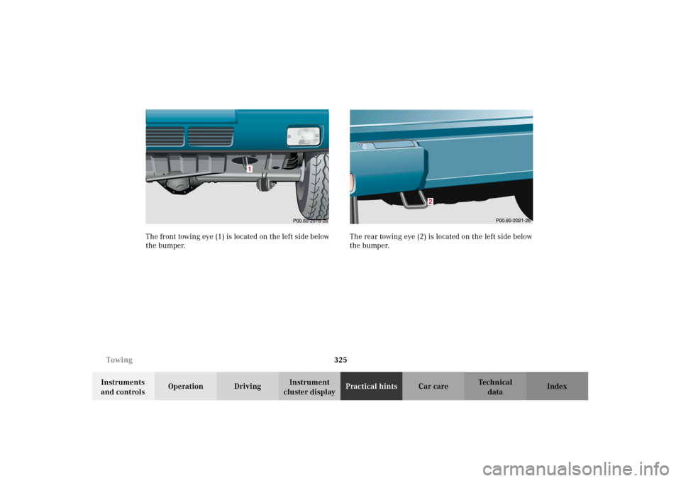
cluster displayPractical hintsCar care Index The front towing eye (1) is located on the left side below
the bumper.The rear towing eye (2) is located on the left side below
the bumper.
J_G463.book Seite 325 Mittwoch, 19. September 2001 8:06 08
Page 329 of 385
326 Towing
Te ch n i c a l
data Instruments
and controlsOperation DrivingInstrument
cluster displayPractical hintsCar care Index
Engine damage /Transmission damage,
Electrical malfunction
To be certain to avoid additional damage to the vehicle
powertrain, however you should do the following:
Shift automatic transmission to position “N”.
Important!
Vehicle may be towed for distances up to 30 miles
(50 km) and at a speed not to exceed 30 mph
(50 km/h).
For towing vehicle for distances exceeding 30 miles
(50 km) or if the vehicle has a damaged transfer
case, remove drive shafts to the drive axles.
When towing vehicle with one axle raised, the
electronic key in starter switch must be in
position 1.
With damage to front axle, raise front axle. Remove
drive shaft between rear axle and transfer case.
With damage to rear axle, raise rear axle and tow
vehicle with wheel lift or dolly placed under front
wheels.Notes:
When removing drive shaft, place M10 nuts on bolts as
distance sleeves and tighten using M8 nuts.
Always install new self-locking nuts when reinstalling
the drive shaft.
Caution!
If the vehicle is towed with the front axle raised, the
engine must be shut off (electronic key in starter switch
position 1). Otherwise, the 4-ETS may become engaged
which may cause loss of towing control. Switch off the
tow-away alarm (see page 43) as well as the ESP (see
page 245).
Note:
To signal turns while being towed with hazard warning
flasher in use, turn electronic key in starter switch to
position 1 and activate combination switch for left or
right turn signal in usual manner. Now deactivate the
hazard warning flasher, only the selected turn signal
will operate. Upon canceling the turn signal, the hazard
warning flasher must be activated again.
J_G463.book Seite 326 Mittwoch, 19. September 2001 8:06 08
Page 330 of 385
327 Towing
Te ch n i c a l
data Instruments
and controlsOperation DrivingInstrument
cluster displayPractical hintsCar care Index Transmission selector lever, manually unlocking
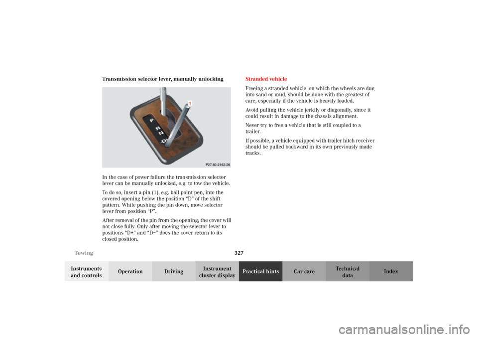
In the case of power failure the transmission selector
lever can be manually unlocked, e.g. to tow the vehicle.
To do so, insert a pin (1), e.g. ball point pen, into the
covered opening below the position “D” of the shift
pattern. While pushing the pin down, move selector
lever from position “P”.
After removal of the pin from the opening, the cover will
not close fully. Only after moving the selector lever to
positions “D+” and “D–” does the cover return to its
closed position.Stranded vehicle
Freeing a stranded vehicle, on which the wheels are dug
into sand or mud, should be done with the greatest of
care, especially if the vehicle is heavily loaded.
Avoid pulling the vehicle jerkily or diagonally, since it
could result in damage to the chassis alignment.
Never try to free a vehicle that is still coupled to a
trailer.
If possible, a vehicle equipped with trailer hitch receiver
should be pulled backward in its own previously made
tracks.
J_G463.book Seite 327 Mittwoch, 19. September 2001 8:06 08