MERCEDES-BENZ GL SUV 2012 Owners Manual
Manufacturer: MERCEDES-BENZ, Model Year: 2012, Model line: GL SUV, Model: MERCEDES-BENZ GL SUV 2012Pages: 441, PDF Size: 10.66 MB
Page 261 of 441

Make sur
ethat the followin gvalues are not
exceeded:
R the permissible trailer drawba rnoseweight
R the permissible trailer load
R the permissible rea raxle load of the towing
vehicle
R the maximum permissible gros svehicle
weight of both the towing vehicle and the
trailer
The applicable permissible values, which
must not be exceeded, can be found:
R in the vehicle documents
R on the identification plates of the trailer tow
hitch, the trailer and the vehicle
If the values differ, the lowest value applies.
You will fin dthe values approved by the man-
ufacturer on the vehicle identification plates
and those for the towing vehicle under "Tech-
nical data "(Ypage 433).
When towing atrailer, your vehicle's handling
characteristics wil lbedifferent in comparison
to when drivin gwithout atrailer.
Th ev ehicle/ trailer combination:
R is heavier
R is restricted in its acceleration and gradi-
ent-climbin gcapability
R has an increased braking distance
R is affected more by stron gcrosswinds
R demand smore sensitive steering
R has alarger turnin gcircle
This could impair the handling charac teris-
tics. Adapt your styl eofdriving accordingly.
Maintain asafe distance. Drive carefully.
When towing atrailer, alw aysa djust your
speed to the current road and weather con-
ditions. Do not exceed the maximum permis-
sible speed for your vehicle/trailer combina-
tion.
General notes !
Use adrawbar noseweigh tasc lose as
possible to the maximum permissible nose-
weight. Do not use anoseweight of less than 50kg, otherwise the trailer ma
ycome
loose.
Not ethat the payload and the rea raxle load
are reduce dbythe actual payload.
i Chec kthe tyr epressures when towin ga
trailer. You will find the values in the tyre
pressure table in the fuel filler flap of the
vehicle (Y page 399).
You will find installation dimensions and loads
in the "Technical data" section
(Y page 432).
The maximum permissible trailer drawbar
noseweight on the ball coupling is 140 kg.
However, the actual noseweight must not
exceed the value given on the trailer tow hitch
or trailer identification plates .The lowest
weight applies.
Please not ethat when towing atrailer, PARK-
TRONIC (Y page 216) and Blind Spo tAssist
(Y page 238) ar eonly available with limita-
tions ,orn ot at all.
Driving tips i
Observ ethe information on ESP ®
trailer
stabilisation (Y page 67)and on pulling
away with atrailer. (Y page 162).
Vehicle swith the ON&OFFROAD pack-
age: select the trailer program (Y page 250)
with the off- road program selector wheel in
the centre console.
The maximum permissible spee dfor vehicle/
trailer combina tions depends on the type of
trailer .Befor ebeginning the journey, check
the trailer's document stosee what the max-
imu mpermitted speed is. Observ ethe legally
prescribed maximum speed in the relevant
country.
For cer tain Mercedes-Benz vehicles, the max-
imum permissible rear axle load is increased
when towing atrailer. See "Technica ldata" to
find out whethe rthis applies to your vehicle
(Y page 433). If you utilise any of the added
maximum rea raxle load whe ntowing atrailer,
th ev ehicle/ trailer combination may not
exceed amaximum spee dof100 km/h for 258
Towin
gatrailerDriving an dparking
Page 262 of 441
reasons concerning th
eoperating permit.
This also applie sincountries in which the
permissible maximum speed for vehicle/
trailer combinations is above 100 km/h.
When towing atrailer, your vehicle's handling
characteristics wil lbedifferen tincomparison
to when drivin gwithout atrailer and it will
consume more fuel.
On long and stee pdownhil lgradients ,you
must select shift range 1,2or 3in good time.
i This also applies if you have activated
cruise con trol, SPEEDTRONIC or DI S-
TRONIC PLUS.
This will use the brakin geffect of th eengine,
so les sbraking wil lberequired to prevent the
vehicle from gainin gspeed. This relieves the
load on the brak esystem and prevent sthe
brakes from overheating and wearing too
quickly .Ifyou need additional braking,
depress the brake pedal repeatedly rather
than con tinuously.
Driving tips If the trailer swings from sid
etoside:
X Do not accelerate.
X Do not countersteer.
X Brake if necessary.
R Maintain agreater distance from th evehi-
cle in front than when driving without a
trailer.
R Avoid braking abruptly. If possible, brake
gently at first to allow the trailer to run on.
Then, increase the braking force rapidly.
R The values given for gradient-climbing
capabilities from astandstill refer to sea
level. Whe ndriving in mountainou sareas,
note that th epower outpu tofthe engine,
and consequen tlyt he vehicle' sgradient-
climbing capability ,decrease with increas-
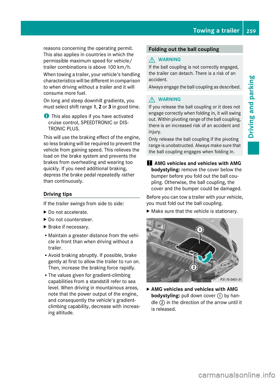
ing altitude. Folding out the ball coupling
G
WARNING
If the ball coupling is not correctly engaged,
the trailer can detach. There is arisk of an
accident.
Always engage the ball coupling as described. G
WARNING
If you release the ball coupling or it does not
engage correctly when folding in, it will swing
out. Within pivoting range of the ball coupling,
there is an increased risk of an accident and
injury.
Only release the ball coupling if the pivoting
range is unobstruc ted. Alway smake sure that
the ball coupling engages when folding in.
! AMG vehicles and vehicles with AMG
bodystyling: remove the cover below the
bumper before you fold out the ball cou-
pling. Otherwise, the ball coupling, the
cover and the bumper could be damaged.
Before you can tow atrailer with your vehicle,
yo um ust fold out the ball coupling.
X Make sure that the vehicle is stationary. X
AMG vehicles and vehicles with AMG
bodystyling: pull down cover :by han-
dle ;in the direction of the arrow until it
is released. Towin
gatrailer
259Driving an dparking Z
Page 263 of 441

X
AMG vehicles and vehicles with AMG
bodystyling: release cover =from the
bracket at the rea rand sto witsafely. X
Open the tailgate.
X Pull release knob :until the ball coupling
unlocks.
The ball coupling folds out from under the
rear bumper.
The indicator lamp on the release knob
flashes .The trailer socket folds away auto-
matically. X
Press the ball couplin ginthe direction of
the arrow until it engages in avertical posi-
tion.
The indicator lam ponthe release knob
goes off.
The multifunction display shows the
Chec ktrailer hitch lock message
until th eball coupling is engaged.
X Remove the protective covering from the
ball coupling and store it in asafe place. Coupling up
atrailer
Important safety notes G
WARNING
Vehicles with level control:
If you disconnec tthe trailer cable, the vehicle
is lowered. This can cause you or other sto
become trapped between the vehicl ebody
and tyres, or underneat hthe vehicle. This
poses arisk of injury.
Make sure that no-on eisinthe immediate
vicinit yofthe wheel arch or underneath the
vehicle when disconnectin gthe trailer cable.
Vehicles with th eAIRMATIC package X
Make sure that the transmission is in posi-
tion P.
X Engage the electric parking brake.
X Start the engine.
X Set the vehicle to highway level
(Y page 213).
X Set the Adaptive Damping System (ADS )to
AUTO orCOMF (Ypage 212).
X Switch off the engine.
X Close the doors and tailgate.
X Position the trailer level behind the vehicle.
X Coupl eupthe trailer.
X Establish the electric con nectio nbetween
the vehicle and the trailer.
X Check that the trailer lighting system is
working. 260
Towing
atrailerDriving an dparking
Page 264 of 441

i
If yo uhave coupled atrail er,the vehicle
will remain at highwa ylevel.
The vehicle automatically lowers to high-
way level if you driv efaster than 30km/h
with atrailer. The vehicle is not lowered to
high-speed level even if you are travelling
at higher speeds.
This also applies when using accessories
that are plugged int othe socket of the
trailer tow hitc h(e.g .ab icycle rack). Uncoupling
atrailer
Importan tsafety notes G
WARNING
If yo uuncoupl eatrailer with an engaged over-
ru nb rake ,you coul dtrap your hand be tween
th ev ehicle and th etrailer drawbar .This poses
ar isk of injury.
Do not uncouple atrailer wit hanengaged
overrun brake. G
WARNING
Vehicle swith level control:
If you disconnec tthe trailer cable, the vehicle
is lowered. This can cause you or other sto
become trapped between the vehicl ebody
and tyres, or underneat hthe vehicle. This
poses arisk of injury.
Make sure that no-on eisinthe immediate
vicinit yofthe wheel arch or underneath the
vehicle when disconnectin gthe trailer cable.
! Do not disconnec tatrailer with an
engaged overrun brake. Otherwise, your
vehicl ecould be damaged by the rebound-
ing of the overru nbrake.
! Remove th einstalled adapter cable
before folding in the ball coupling. Other-
wise, damage may occur to the rear
bumpe rand the adapter cable. Vehicle
swith the AIRMATIC package X
Make sure that the transmission is in posi-
tion P.
X Engage the electric parking brake.
X Star tthe engine.
X Close the doors and tailgate.
X Secur ethe trailer against rolling away.
X Remove the trailer cable and decouple the
trailer.
X Switc hoff th eengine. Folding in the ball coupling
G
WARNING
If you releas ethe ball coupling or it does not
engage correc tlyw hen folding in, it will swing
out. Within pivotin grange of the ball coupling,
there is an increased risk of an accident and
injury.
Only release the ball coupling if the pivoting
range is unobstructed. Always make sure that
the ball coupling engages when folding in.
Fold the ball coupling back in if you are not
using the trailer tow hitch.
X Make sure that the vehicle is stationary and
the trailer cables are disconnected.
X Place the protective covering on the ball
coupling.
X Open the tailgate. Towin
gatrailer
261Driving an dparking Z
Page 265 of 441

X
Pull release knob :until the ball coupling
unloc ks.
The ball coupling folds down from under the
rea rbumper. The indicator lamp on the
release knob flashes.
i Do not attempt to spee dupthis process
by usin gyour foot to apply additional pres-
sure .Otherwise, the syste mmay sustain
mechanical damage. X
Press the ball coupling in the direction of
the arrow until it engages audibl ybehind
the bumper.
The indicator lam ponthe release knob
goes out and the message in the multifunc-
tion displa ydisappears. X
AMG vehicles and vehicles with AMG
bodystyling: attachhooks ;of cover =
in the direction of the arrow int oopen-
ings :intended for this purpose. X
AMG vehicle sand vehicles with AMG
bodystyling: push cover?upwards in the
direction of the arrow until it engages.
X AMG vehicles and vehicles with AMG
bodystyling: check that cover ?has been
atta ched correctly. Trailer powe
rsupply
! Youc an connect accessories with a
power rating of up to 240 Wtothe perma-
nen tpower supply and with apower rating
of up to 18 0Wto the powe rsupply that is
switched on via the ignition lock.
The trailer batter ymay not be charged from
the power supply.
When it leaves the factory, your vehicle's
trailer socket is equippe dwithapermanent
power supply and apower supply that is
switched on via the ignition lock.
The permanen tpower supply is supplied via
trailer socket pin 9.
The power supply that is switched on via the
ignition lock is supplied via trailer socket pin
10.
The trailer's permanen tpower supply is
switched off in the even toflow vehicle supply
voltage and after six hour satthe latest.
You can fin dmore information about fit ting
the trailer electric sataqualified specialist
workshop.
X To switch the connected power supply
on or off: turn the key in the ignition lock 262
Towin
gatrailerDriving an dparking
Page 266 of 441
. Bulb fa
ilure indicato rfor LEDl amps
i If LED lamps ar efitted in the trai ler, an
error message ma yappea rinthe multi-
function display eve nifthere is")
to position
2or 0respective ly
( Y page 159). Bulb fa
ilure indicato rfor LEDl amps
i If LED lamps ar efitted in the trai ler, an
error message ma yappea rinthe multi-
function display eve nifthere is no fault .The
reason for the err or message could be that
the curren thas fallen below the minimum
of 50 mA.
To ensur ereliable operation of the bulb failure
indicator, each LE Dchain in the trailer lighting
must be guaranteed aminimum curren tof
50 mA. Trailer wit
h7-pin connector
General notes Trailers with 7-pi
nconnector: you can
make aconnection to the 13 -pin connector
on the ball coupling using an adapter plug or,
if necessary, an adapter cable. Bot hcan be
obtained in aqualified specialist workshop.
Fitting the adapter !
Make sure that there is sufficien tcable
play so that the cable cannot become
detached when cor nering.
! Remove th einstalled adapter cable
before folding in the ball coupling. Other-
wise, damage may occur to the rear
bumpe rand the adapter cable. X
Ope nthe socket cover.
X Inser tconnector with lug :into
groove ;of the socket. Tur nthe connec-
tor cloc kwise to the stop.
X Let the cover engage.
X If you are using an adapter cable, secure
the cable to the trailer with cable ties. Towing
atrailer
263Driving an dparking Z
Page 267 of 441

Problems wit
htrailer towing Problem Possible causes/consequences and
M Solutions
The released ball cou-
pling cannot be
engaged. X
Visit aqualified specialist workshop. The ball coupling does
not unlock, even
though:
R
the vehicle is station-
ary
R no trailer cable is
connected
R the release knob to
unlock the ball cou-
pling has been pulled
for more than asec-
ond. The on-boar
dvoltage is insufficient.
X Start the engine.
If the ball coupling still does not unlock:
X Visit aqualified specialist workshop. 264
Towin
gatrailerDriving an dparking
Page 268 of 441

Usefu
linfor mation ............................ 266
Important safet ynotes .................... 266
Displays and oper ation .................... 267
Menu sand submenus ...................... 271
Displa ymessages ............................. 290
Wa rning and indicator lamp sinthe
instrumen tcluster ............................ 324 265On-boar
dcomputer and displays
Page 269 of 441

Usefu
linfor mati on
i This Owner's Manual describes all mod-
els, series and optional equipment for your
vehicle that were available at the time of
going to press. National variation sare pos-
sible. Note that your vehicl emay not be
equippe dwith all of the function sdescri-
bed. This is also the case for system sand
functions relevant to safety.
i Read the information on qualified special-
ist workshops: (Y page25). Impo
rtantsafety notes G
WARNING
Onl yuse the on-boar dcompu terw hen road
and traffic condition spermit .You would oth-
erwise be distracted and unable to concen-
trate properly on driving, and coul dcause an
accident. G
WARNING
No message swill be displayed if either the
instrument cluster or the multifunction dis-
play is inoperative.
As aresult, you will not be able to see infor-
mation about your driving conditions, such as
speed, outside temperature, warning and indi-
cator lamps, display messages or system fail-
ures. Drivin gcharacteristic smay be impaired.
Adjust your driving style and vehicle speed
accordingly.
Contact aqualified specialist workshop
immediately. G
WARNING
The on-board computer only records and dis-
plays malfunctions and warnings from certain
systems. For this reason, you should always
make sure that your vehicle is safe to use. You
could otherwis ecause an accident by driving
an unsafe vehicle. G
WARNING
The operating safety of your vehicle could be
impaired if maintenance work is carried out
incorrectly. This could cause you to lose con-
trol of your vehicle and cause an accident.
Moreover, the safety systems may no longer
be able to protect you or others as they are
designed to do.
Always have service work carried out at a
qualified specialis tworkshop.
For an illustration of the instrumen tcluster,
see (Y page 30). 266
Important safety notesOn-board computer and displays
Page 270 of 441

; Fue lgauge
= Rev counter (Y page 268)
? Coolant temperature (Y page 268)
A Multif")
Display
sand operation In
strument clu ster Instrument clu
ster: kilometres
: Speedometer wit hsegments (Y page 268)
; Fue lgauge
= Rev counter (Y page 268)
? Coolant temperature (Y page 268)
A Multifunction display (Y page 270)
B Instrumen tcluster lightin g(Ypage 26 8) Instrument cluster: miles
:
Speedometer with segments (Y page 268)
; Fue lgauge Display
sand ope ration
267On-board computer and displays Z