clock MERCEDES-BENZ GLE COUPE 2015 Owners Manual
[x] Cancel search | Manufacturer: MERCEDES-BENZ, Model Year: 2015, Model line: GLE COUPE, Model: MERCEDES-BENZ GLE COUPE 2015Pages: 393, PDF Size: 12.71 MB
Page 90 of 393
X
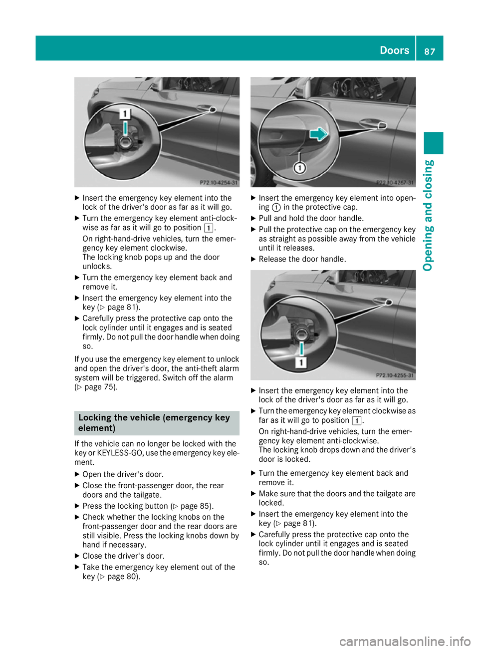
Insert the emergency key element into the
lock of the driver's door as far as it will go.
X Turn the emergency key element anti-clock-
wise as far as it will go to position 1.
On right-hand-drive vehicles, turn the emer-
gency key element clockwise.
The locking knob pops up and the door
unlocks.
X Turn the emergency key element back and
remove it.
X Insert the emergency key element into the
key (Y page 81).
X Carefully press the protective cap onto the
lock cylinder until it engages and is seated
firmly. Do not pull the door handle when doing
so.
If you use the emergency key element to unlock
and open the driver's door, the anti-theft alarm
system will be triggered. Switch off the alarm
(Y page 75). Locking the vehicle (emergency key
element)
If the vehicle can no longer be locked with the
key or KEYLESS-GO, use the emergency key ele- ment.
X Open the driver's door.
X Close the front-passenger door, the rear
doors and the tailgate.
X Press the locking button (Y page 85).
X Check whether the locking knobs on the
front-passenger door and the rear doors are
still visible. Press the locking knobs down by
hand if necessary.
X Close the driver's door.
X Take the emergency key element out of the
key (Y page 80). X
Insert the emergency key element into open-
ing :in the protective cap.
X Pull and hold the door handle.
X Pull the protective cap on the emergency key
as straight as possible away from the vehicle until it releases.
X Release the door handle. X
Insert the emergency key element into the
lock of the driver's door as far as it will go.
X Turn the emergency key element clockwise as
far as it will go to position 1.
On right-hand-drive vehicles, turn the emer-
gency key element anti-clockwise.
The locking knob drops down and the driver's door is locked.
X Turn the emergency key element back and
remove it.
X Make sure that the doors and the tailgate are
locked.
X Insert the emergency key element into the
key (Y page 81).
X Carefully press the protective cap onto the
lock cylinder until it engages and is seated
firmly. Do not pull the door handle when doing
so. Doors
87Opening and closing Z
Page 135 of 393
Problems with the "Cooling with air dehumidification" function
Problem
Possible causes/consequences and
M
MSolutions The indicator lamp in the
¿ orÁ button
flashes three times or
remains off. The cooling
with air dehumidification
function cannot be acti-
vated. The cooling with air dehumidification function has been deactivated
due to a malfunction.
X Consult a qualified specialist workshop. Setting climate control to automatic
mode
General notes In automatic mode, the set temperature is main-
tained automatically at a constant level. The
system automatically regulates the temperature of the dispensed air, the airflow and the air dis- tribution.
The "Cooling with air dehumidification" function
is activated automatically in automatic mode.
In the rear compartment, you can also switch
climate control for the rear seats to automatic
mode using the Ãbutton.
Automatic control X
Turn the key to position 2in the ignition lock
(Y page 146).
X Set the desired temperature.
X To activate: press theÃbutton.
The indicator lamp in the Ãbutton lights
up. Automatic air distribution and airflow are
activated.
X To switch to manual mode: press the_
button.
or X Press the IorK button.
The indicator lamp in the Ãbutton goes
out.
THERMOTRONIC automatic climate control:
when automatic mode is activated, you can
select a climate mode (Y page 132). Setting the climate mode
In automatic mode you can select the following
climate modes:
FOCUS high airflow, slightly cooler setting
MEDIUM medium airflow, standard setting
DIFFUSE low airflow, slightly warmer and draught-free setting
X Turn the key to position 2in the ignition lock
(Y page 146).
X Press the Ãbutton.
X Press the ñbutton repeatedly until the
desired climate mode appears in the display. Setting the temperature
THERMATIC automatic climate control Different temperatures can be set for the driv-
er's and front-passenger sides.
X Turn the key to position 2in the ignition lock
(Y page 146).
X To increase or decrease: turn control:or
B anti-clockwise or clockwise (Y page 127).
Only change the temperature setting in small increments. Start at 22 †. 132
Operating the climate control systemClimate control
Page 136 of 393
THERMOTRONIC automatic climate
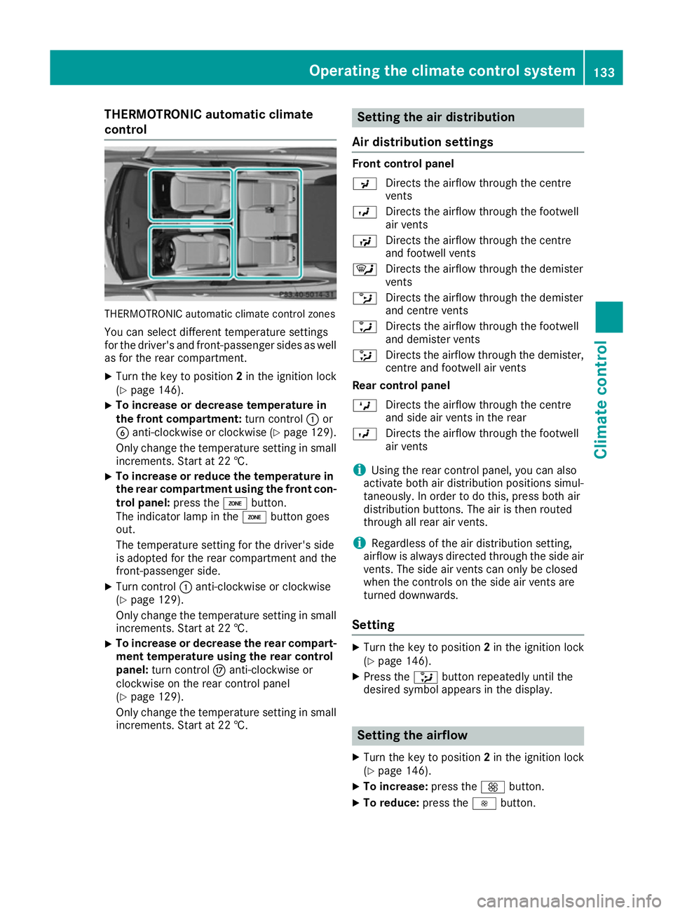
control THERMOTRONIC automatic climate control zones
You can select different temperature settings
for the driver's and front-passenger sides as well
as for the rear compartment.
X Turn the key to position 2in the ignition lock
(Y page 146).
X To increase or decrease temperature in
the front compartment:
turn control:or
B anti-clockwise or clockwise (Y page 129).
Only change the temperature setting in small
increments. Start at 22 †.
X To increase or reduce the temperature in
the rear compartment using the front con-
trol panel: press theábutton.
The indicator lamp in the ábutton goes
out.
The temperature setting for the driver's side
is adopted for the rear compartment and the
front-passenger side.
X Turn control :anti-clockwise or clockwise
(Y page 129).
Only change the temperature setting in small
increments. Start at 22 †.
X To increase or decrease the rear compart-
ment temperature using the rear control
panel: turn control Manti-clockwise or
clockwise on the rear control panel
(Y page 129).
Only change the temperature setting in small
increments. Start at 22 †. Setting the air distribution
Air distribution settings Front control panel
P
Directs the airflow through the centre
vents
O Directs the airflow through the footwell
air vents
S Directs the airflow through the centre
and footwell vents
¯ Directs the airflow through the demister
vents
b Directs the airflow through the demister
and centre vents
a Directs the airflow through the footwell
and demister vents
_ Directs the airflow through the demister,
centre and footwell air vents
Rear control panel
M Directs the airflow through the centre
and side air vents in the rear
O Directs the airflow through the footwell
air vents
i Using the rear control panel, you can also
activate both air distribution positions simul-
taneously. In order to do this, press both air
distribution buttons. The air is then routed
through all rear air vents.
i Regardless of the air distribution setting,
airflow is always directed through the side air vents. The side air vents can only be closed
when the controls on the side air vents are
turned downwards.
Setting X
Turn the key to position 2in the ignition lock
(Y page 146).
X Press the _button repeatedly until the
desired symbol appears in the display. Setting the airflow
X Turn the key to position 2in the ignition lock
(Y page 146).
X To increase: press theKbutton.
X To reduce: press theIbutton. Operating the climate control system
133Climate control
Page 137 of 393
i
You can use THERMOTRONIC automatic cli-
mate control to set the airflow in the rear
compartment separately. Switching the ZONE function on/off
X To activate: press theábutton.
The indicator lamp above the ábutton
lights up.
THERMATIC automatic climate control: the
temperature setting for the driver's side is not
adopted for the front-passenger side.
THERMOTRONIC automatic climate control:
the temperature setting for the driver's side is
not adopted for the front-passenger side and
the rear compartment.
X To deactivate: press theábutton.
The indicator lamp above the ábutton
goes out.
THERMATIC automatic climate control: the
temperature setting for the driver's side is
adopted for the front-passenger side.
THERMOTRONIC automatic climate control:
the temperature setting for the driver's side is adopted for the front-passenger side and the rear compartment. Demisting the windscreen
General notes You can use this function to defrost the wind-
screen or to demist the inside of the windscreen
and the front side windows.
Switch off the windscreen demisting function as
soon as the windscreen is clear again.
Switching on/off X
Turn the key to position 2in the ignition lock
(Y page 146).
X To activate: press the¬button.
The indicator lamp in the ¬button lights
up.
The climate control system switches to the
following functions:
R high airflow
R high temperature R
air distribution to the windscreen and front
side windows
R air-recirculation mode off
X To deactivate: press the¬button.
The indicator lamp in the ¬button goes
out. The previous settings are reactivated.
Air-recirculation mode remains deactivated.
or X Press the Ãbutton.
The indicator lamp in the ¬button goes
out. Airflow and air distribution are set to
automatic mode.
or X Turn control :orB anti-clockwise or clock-
wise:
THERMATIC automatic climate control
(Y page 127)
THERMOTRONIC automatic climate control
(Y page 129)
or
X Press the KorI button. Demisting the windows
Windows misted up on the inside X
Activate the ¿orÁ cooling with air
dehumidification function.
X Activate automatic mode Ã.
X If the windows continue to mist up, activate
the "Windscreen demisting" function
(Y page 134).
i You should only select this setting until the
windscreen is clear again.
Windows misted up on the outside X
Switch on the windscreen wipers.
X Press the _button repeatedly until the
P orO symbol appears in the display.
i You should only select this setting until the
windscreen is clear again.
i If you clean the windows regularly, they do
not mist up so quickly. 134
Operating the climate control systemClimate control
Page 166 of 393
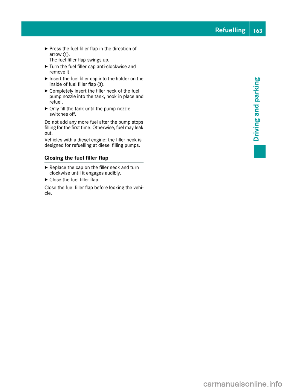
X
Press the fuel filler flap in the direction of
arrow :.
The fuel filler flap swings up.
X Turn the fuel filler cap anti-clockwise and
remove it.
X Insert the fuel filler cap into the holder on the
inside of fuel filler flap ;.
X Completely insert the filler neck of the fuel
pump nozzle into the tank, hook in place and
refuel.
X Only fill the tank until the pump nozzle
switches off.
Do not add any more fuel after the pump stops
filling for the first time. Otherwise, fuel may leak
out.
Vehicles with a diesel engine: the filler neck is
designed for refuelling at diesel filling pumps.
Closing the fuel filler flap X
Replace the cap on the filler neck and turn
clockwise until it engages audibly.
X Close the fuel filler flap.
Close the fuel filler flap before locking the vehi-
cle. Refuelling
163Driving and parking Z
Page 169 of 393
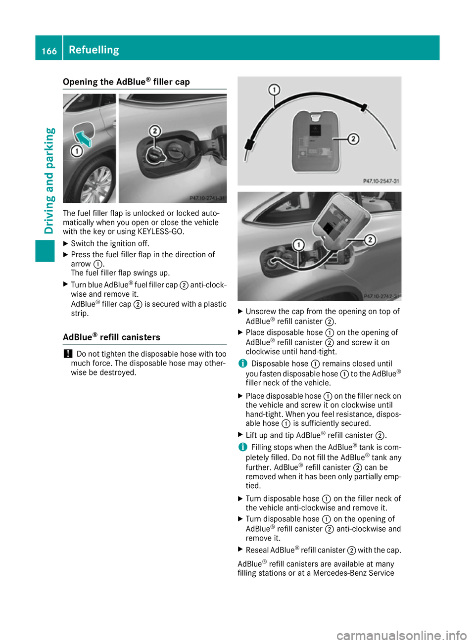
Opening the AdBlue
®
filler cap The fuel filler flap is unlocked or locked auto-
matically when you open or close the vehicle
with the key or using KEYLESS-GO.
X Switch the ignition off.
X Press the fuel filler flap in the direction of
arrow :.
The fuel filler flap swings up.
X Turn blue AdBlue ®
fuel filler cap ;anti-clock-
wise and remove it.
AdBlue ®
filler cap ;is secured with a plastic
strip.
AdBlue ®
refill canisters !
Do not tighten the disposable hose with too
much force. The disposable hose may other-
wise be destroyed. X
Unscrew the cap from the opening on top of
AdBlue ®
refill canister ;.
X Place disposable hose :on the opening of
AdBlue ®
refill canister ;and screw it on
clockwise until hand-tight.
i Disposable hose
:remains closed until
you fasten disposable hose :to the AdBlue ®
filler neck of the vehicle.
X Place disposable hose :on the filler neck on
the vehicle and screw it on clockwise until
hand-tight. When you feel resistance, dispos-
able hose :is sufficiently secured.
X Lift up and tip AdBlue ®
refill canister ;.
i Filling stops when the AdBlue ®
tank is com-
pletely filled. Do not fill the AdBlue ®
tank any
further. AdBlue ®
refill canister ;can be
removed when it has been only partially emp-
tied.
X Turn disposable hose :on the filler neck of
the vehicle anti-clockwise and remove it.
X Turn disposable hose :on the opening of
AdBlue ®
refill canister ;anti-clockwise and
remove it.
X Reseal AdBlue ®
refill canister ;with the cap.
AdBlue ®
refill canisters are available at many
filling stations or at a Mercedes-Benz Service 166
RefuellingDriving and parking
Page 170 of 393
Centre. AdBlue
®
refill canisters are often sold
with a filler hose. A filler hose that does not
exactly fit the vehicle's AdBlue ®
tank offers no
protection against overfilling. AdBlue ®
may leak
out as a result of overfilling. Mercedes-Benz
offers a special disposable hose with overfill
protection. You can obtain this from any
Mercedes-Benz Service Centre. AdBlue ®
is
available in a variety of containers and recepta- cles. Only use the disposable hose with the
Mercedes-Benz AdBlue ®
refill canisters.
AdBlue ®
refill bottle !
Screw on the AdBlue ®
refill bottle only hand-
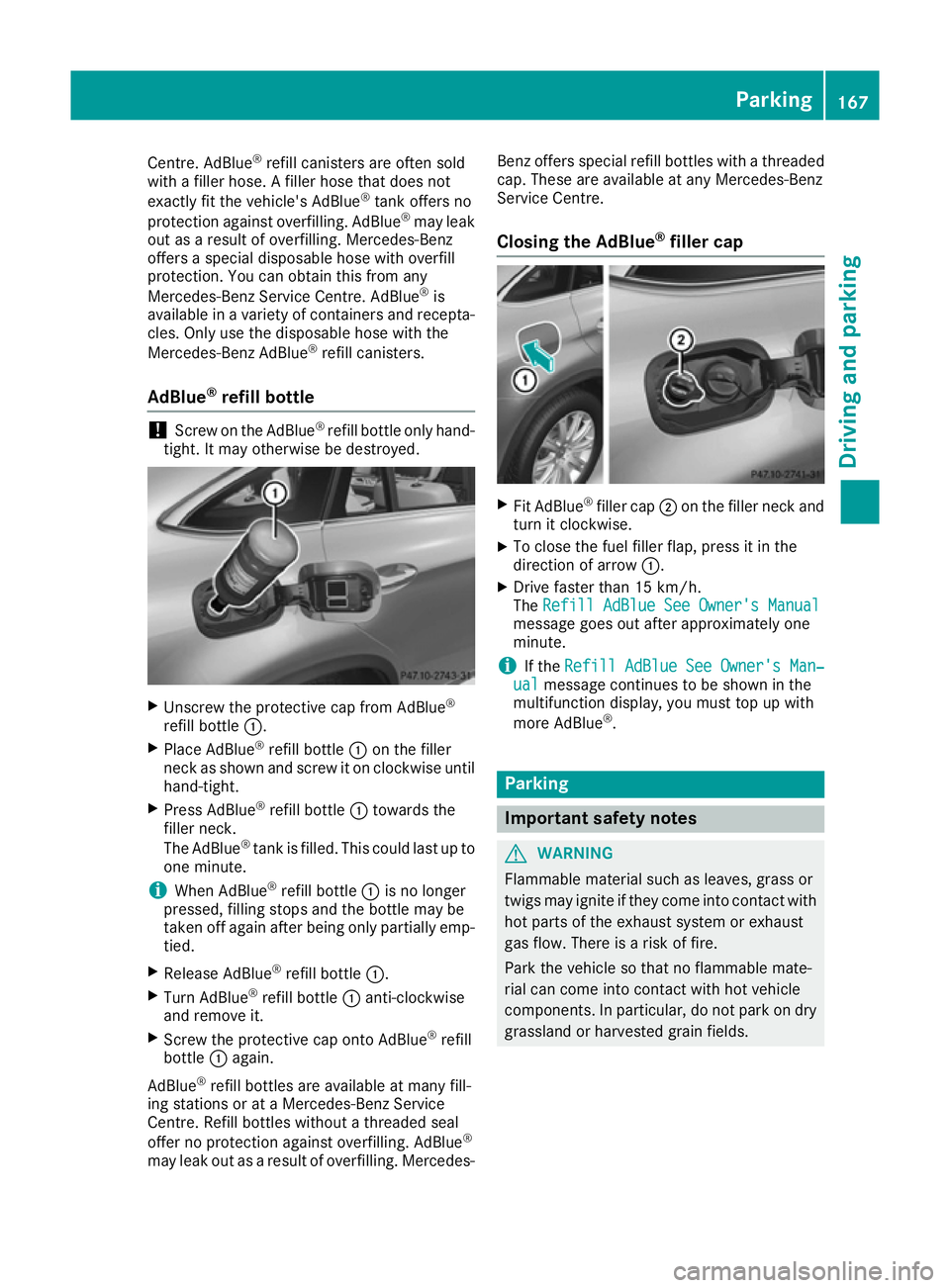
tight. It may otherwise be destroyed. X
Unscrew the protective cap from AdBlue ®
refill bottle :.
X Place AdBlue ®
refill bottle :on the filler
neck as shown and screw it on clockwise until hand-tight.
X Press AdBlue ®
refill bottle :towards the
filler neck.
The AdBlue ®
tank is filled. This could last up to
one minute.
i When AdBlue ®
refill bottle :is no longer
pressed, filling stops and the bottle may be
taken off again after being only partially emp- tied.
X Release AdBlue ®
refill bottle :.
X Turn AdBlue ®
refill bottle :anti-clockwise
and remove it.
X Screw the protective cap onto AdBlue ®
refill
bottle :again.
AdBlue ®
refill bottles are available at many fill-
ing stations or at a Mercedes-Benz Service
Centre. Refill bottles without a threaded seal
offer no protection against overfilling. AdBlue ®
may leak out as a result of overfilling. Mercedes- Benz offers special refill bottles with a threaded
cap. These are available at any Mercedes-Benz
Service Centre.
Closing the AdBlue ®
filler cap X
Fit AdBlue ®
filler cap ;on the filler neck and
turn it clockwise.
X To close the fuel filler flap, press it in the
direction of arrow :.
X Drive faster than 15 km/h.
The Refill AdBlue See Owner's Manual Refill AdBlue See Owner's Manual
message goes out after approximately one
minute.
i If the
Refill AdBlue See Owner's Man‐ Refill AdBlue See Owner's Man‐
ual
ual message continues to be shown in the
multifunction display, you must top up with
more AdBlue ®
. Parking
Important safety notes
G
WARNING
Flammable material such as leaves, grass or
twigs may ignite if they come into contact with hot parts of the exhaust system or exhaust
gas flow. There is a risk of fire.
Park the vehicle so that no flammable mate-
rial can come into contact with hot vehicle
components. In particular, do not park on dry grassland or harvested grain fields. Parking
167Driving and parking Z
Page 235 of 393
Further information:
R Display messages when towing a trailer
(Y page 281)
R Problems when swivelling the ball coupling
(Y page 233) Trailer power supply
! You can connect accessories with a power
rating of up to 180 W to the permanent power supply and with a power rating of up to 180 Wto the power supply that is switched on via the
ignition lock.
The trailer battery may not be charged from
the power supply.
When it leaves the factory, your vehicle's trailer
socket is equipped with a permanent power
supply and a power supply that is switched on
via the ignition lock.
The permanent power supply is supplied via
trailer socket pin 9.
The power supply that is switched on via the
ignition lock is supplied via trailer socket pin 10. The trailer's permanent power supply is
switched off in the event of low vehicle supply
voltage and after six hours at the latest.
You can find more information about fitting the
trailer electrics at a qualified specialist work-
shop.
X To switch the connected power supply on
or off: turn the key to position 2or 0respec-
tively (Y page 146). Failure check for LEDs
If LED lamps are fitted in the trailer, a malfunc-
tion message may appear in the multifunction
display even if there is no fault. The reason for
the error message may be that the current has
fallen below the minimum of 50 mA.
To ensure reliable indication of the failure, each LED chain in the trailer lighting must be guaran-
teed a minimum current of 50 mA. Trailer with 7-pin connector
General notes Trailer with 7-pin connector:
you can connect
to the 13-pin socket on the ball coupling using
an adapter or, if necessary, an adapter cable.
Both can be obtained at a qualified specialist
workshop.
Fitting the adapter !
Make sure that there is sufficient cable play
so that the cable cannot become detached
when cornering.
! Remove the adapter cable before folding in
the ball coupling. You could otherwise dam-
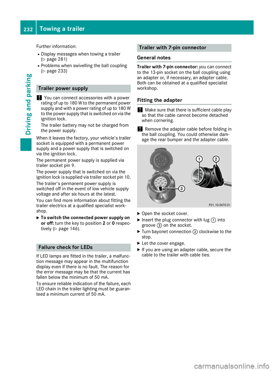
age the rear bumper and the adapter cable. X
Open the socket cover.
X Insert the plug connector with lug :into
groove =on the socket.
X Turn bayonet connection ;clockwise to the
stop.
X Let the cover engage.
X If you are using an adapter cable, secure the
cable to the trailer with cable ties. 232
Towing a trailerDriving and parking
Page 238 of 393
Useful information
i This Owner's Manual describes all models,
series and optional equipment for your vehi-
cle that were available at the time of going to
press. National variations are possible. Note
that your vehicle may not be equipped with all
of the functions described. This is also the
case for systems and functions relevant to
safety.
i Read the information on qualified specialist
workshops: (Y page 25). Important safety notes
G
WARNING
Operating the integrated information systems and communications equipment in the vehicle
while driving will distract you from traffic con-
ditions. You could then lose control of the
vehicle. There is a risk of an accident.
Only operate these devices if road traffic con-
ditions permit. If you are unsure about the
surrounding conditions, pull over to a safe
location and make entries only while the vehi-
cle is stationary.
You must observe the legal requirements for the country in which you are currently driving whenoperating the on-board computer. G
WARNING
If the instrument cluster has failed or mal-
functioned, you may not recognise function
restrictions relevant to safety. The operating
safety of your vehicle may be impaired. There is a risk of an accident.
Drive on carefully. Have the vehicle checked
at a qualified specialist workshop immedi-
ately.
If the operating safety of your vehicle is
impaired, park the vehicle safely as soon as pos- sible. Contact a qualified specialist workshop.
The on-board computer only shows messages or warnings from certain systems in the multifunc-tion display. You should therefore make sure
your vehicle is operating safely at all times. For an overview, see the instrument cluster illus-
tration (Y page 29). Displays and operation
Instrument cluster lighting
The lighting in the instrument cluster, in the dis- plays and the controls in the vehicle interior can
be adjusted using the brightness control knob.
The brightness control knob is located on the
bottom left of the instrument cluster
(Y page 29).
X Turn the brightness control knob clockwise or
anti-clockwise.
If you turn the light switch to Ã,Tor
L, the brightness is dependent upon the
brightness of the ambient light.
i The light sensor in the instrument cluster
automatically controls the brightness of the
multifunction display.
In daylight, the displays in the instrument
cluster are not illuminated. Speedometer with segments
The speedometer is divided into segments only
on vehicles with DISTRONIC PLUS.
The segments in the speedometer indicate
which speed range is available.
R Variable SPEEDTRONIC activated
(Y page 180):
The segments light up from the start of the
scale to the selected limit speed.
R DISTRONIC PLUS activated (Y page 182):
One or two segments in the set speed range
light up.
R DISTRONIC PLUS detects a vehicle in front
moving more slowly than the stored speed:
The segments between the speed of the vehi- cle in front and the stored speed light up. Rev counter
! Do not drive in the overrevving range. Doing
so will damage the engine.
The red band in the rev counter indicates the
engine's overrevving range. Displays and operation
235On-board computer and displays Z
Page 250 of 393
X
Press the :or9 button to select the
Dipped beams Setting for:
Dipped beams Setting for: function.
You will see the selected setting: Right-
Right-
side traffic
side traffic orLeft-side traffic
Left-side traffic.
X Press the abutton to save the setting.
If you change the setting, conversion does not
take place until the next time the vehicle is
stationary.
If you set the dipped-beam headlamps for driv-
ing on the right/left, then motorway mode and
the extended range foglamps are unavailable.
These are only deactivated if the setting for driv-
ing on the left/right is set opposite to your vehi- cle's country version.
A qualified specialist workshop can set the
dipped-beam headlamps for driving on the left/
right.
Vehicle submenu Setting permanent SPEEDTRONIC
X Press the =or; button on the steering
wheel to select the Settings Settingsmenu.
X Press the :or9 button to select the
Vehicle
Vehicle submenu.
X Press ato confirm.
X Press :or9 to select the Limit
Limit
speed (winter tyres):
speed (winter tyres): function.
You will see the current setting.
X Press ato confirm.
X Press the :or9 button to adjust per-
manent SPEEDTRONIC in increments of ten
(240 km/h 240 km/h to160 km/h 160 km/h). The Off
Offsetting
switches permanent SPEEDTRONIC off.
X Press the abutton to store the entry.
For further information on permanent SPEED-
TRONIC (Y page 182).
Activating/deactivating the automatic
locking feature
If you activate the Automatic door locks
Automatic door locks
function, the vehicle is centrally locked above a
speed of approximately 15 km/h.
X Press the =or; button on the steering
wheel to select the Settings
Settings menu.
X Press the :or9 button to select the
Vehicle
Vehicle submenu.
X Press ato confirm. X
Press the :or9 button to select the
Automatic door locks
Automatic door locks function.
When the Automatic
Automatic door
doorlocks
locks function is
activated, the vehicle doors are displayed in
orange in the multifunction display.
X Press the abutton to save the setting.
For further information on the automatic locking feature; see (Y page 86).
Activating/deactivating the acoustic
locking confirmation
If you switch on the Acoustic AcousticLock
Lockfunction, an
acoustic signal sounds when you lock the vehi-
cle.
X Press the =or; button on the steering
wheel to select the Settings Settingsmenu.
X Press the :or9 button to select the
Vehicle
Vehicle submenu.
X Press ato confirm.
X Press the :or9 button to select the
Acoustic Lock
Acoustic Lock function.
If the Acoustic Lock
Acoustic Lock function is activated,
the & symbol in the multifunction display
lights up orange.
X Press the abutton to save the setting.
Heating submenu Auxiliary heating departure time
G
DANGER
If the exhaust pipe is blocked or sufficient
ventilation is not possible, toxic exhaust
fumes can enter the vehicle, especially car-
bon monoxide. This is the case, e.g. in
enclosed spaces, or if the vehicle is stuck in
snow. There is a risk of fatal injuries.
You should switch off the auxiliary heating in
enclosed spaces which do not have an extrac- tion system, e.g. a garage. If the vehicle is
stuck in snow and you must leave the auxiliary
heating running, keep the exhaust pipe and
the area around the vehicle clear of snow. To guarantee a sufficient supply of fresh air, open
a window on the side of the vehicle away from the wind. Menus and submenus
247On-board computer and displays Z