MERCEDES-BENZ GLS SUV 2018 Owner's Manual
Manufacturer: MERCEDES-BENZ, Model Year: 2018, Model line: GLS SUV, Model: MERCEDES-BENZ GLS SUV 2018Pages: 398, PDF Size: 6.75 MB
Page 231 of 398
Decouplingatrailer
GWARNING
If you uncoupl e atrailer wit hth eoverrun
brake engaged, you could trap your han d
between th evehicle and th etrailer drawbar .
There is aris kof injury.
Do no tuncoupl e atrailer if th eoverrun brake
is engaged.
GWARNING
Vehicles wit hlevel control:
The vehicle is lowered as soo nas you discon-
nect th etrailer cable. Thi scould result in your
limbs or those of other people that are
between th evehicle bod yand tires or under-
neat hth evehicle bein gtrapped. There is a
ris kof injury.
Mak esur ethat nobod yis in th eimmediate
vicinit yof th ewhee lhousings or under th e
vehicle when you disconnec tth etrailer cable.
!Do no tdisconnec t atrailer wit han engage d
overrun brake .Otherwise ,your vehicle could
be damaged by th ereboundin gof th eoverrun
brake .
XShift th etransmissio nto position P.
XApply thevehicle' selectric parking brake .
XStart theengine.
XClos eth edoors and tailgate.
XApply th etrailer's parking brake .
XDetach thetrailer cable and decoupl eth e
trailer .
XSwitchof fth eengine.
Permissible trailer loads an ddrawbar
loads
Weight specifications
Maximum allowable gross mass
The gross vehicle weight of th etrailer is calcu-
lated by addin gth eweight of th etrailer to th e
weight of th eload and equipmen ton th etrailer .
You will fin dinstallin gdimensions and load s
under "Technical data" (
Ypage 395).
Permissible noseweigh t
You will findinstallin gdimensions and load s
under "Technical data" (Ypage 395).
Loadingatrailer
RWhe nloadin gth etrailer ,mak esur ethat nei-
ther th epermissible gross weight of th etrailer
no rth egross vehicle weight are exceeded.
The permissible gross vehicle weight is indi-
cated on th eidentification plat elocated on
th eB-pilla ron th edriver's sid eof th evehicle.
You can fin dth emaximum permissible values
on th etyp eplates of your vehicle and th e
trailer .Whe ncalculatin ghow muc hweight
th evehicle and trailer may carry, pay atten-
tion to th erespective lowest values.
RThe trailer drawbar load on th eball couplin g
mus tbe adde dto th erea raxl eload to avoid
exceedin gth epermissible gross axl eweight .
The permissible gross vehicle weight is indi-
cated on th eidentification plat elocated on
th eB-pilla ron th edriver's sid eof th evehicle.
iMercedes-Ben zrecommends atrailer load
wher eth etrailer drawbar noseweigh t
accounts fo r 8 %to 15 %of th etrailer's per -
missible gross weight .
iThe weight of additional accessories ,pas-
sengers, and cargo reduce sth epermissible
trailer load and drawbar load fo ryour vehicle.
Checking th evehicle an dtrailer weigh t
RTo checkthat th eweight sof th etowin gvehi-
cl e and th etrailer compl ywit hth emaximum
permissible values, hav eth evehicle/trailer
combination (includin gth edriver ,passen -
gers, and cargo wit h afullylade ntrailer )
weighed on acalibrated weighbridge .
RCheckth egross axl eweight ratin gof th efron t
and rea raxles, th egross weight of th etrailer
and th etrailer drawbar noseweight.
Removin gth eball coupling
XRemov eth esprin gcotter.
XRemov eth ebolt from th eball couplin g
recess .
XRemov eth eball couplin gfrom th eball cou-
plin grecess .
Towing a trailer229
Driving and parking
Z
Page 232 of 398
XClean theballcouplin gif it is dirt y.
XStow the ballcouplin g so that itcannot be
thrown aroun d.
Observe the loading guidelines (
Ypage 300)
and the safety notes regarding stowage spaces
(
Ypage 300).
In formation on cleaning and care of the trailer
tow hitch (
Ypage 335).
Trailer power supply
!
Accessories with a maximum power con-
sumption of 180 W can beconnected to the
permanent power supply.
You must not charge a trailer battery using the
power supply.
The trailer socket of your veh icle is equipped at
the factory with a permanent power supply.
The permanent power supply is supplied via
trailer socket pin4.
The trailer's permanent power supply is
swit ched off inthe event of low veh icle supply
voltage and after six hours at the latest.
A qualif ied specialist workshop can provide
more information about installing the trailer
electrics.
Bicycle rack
General notes
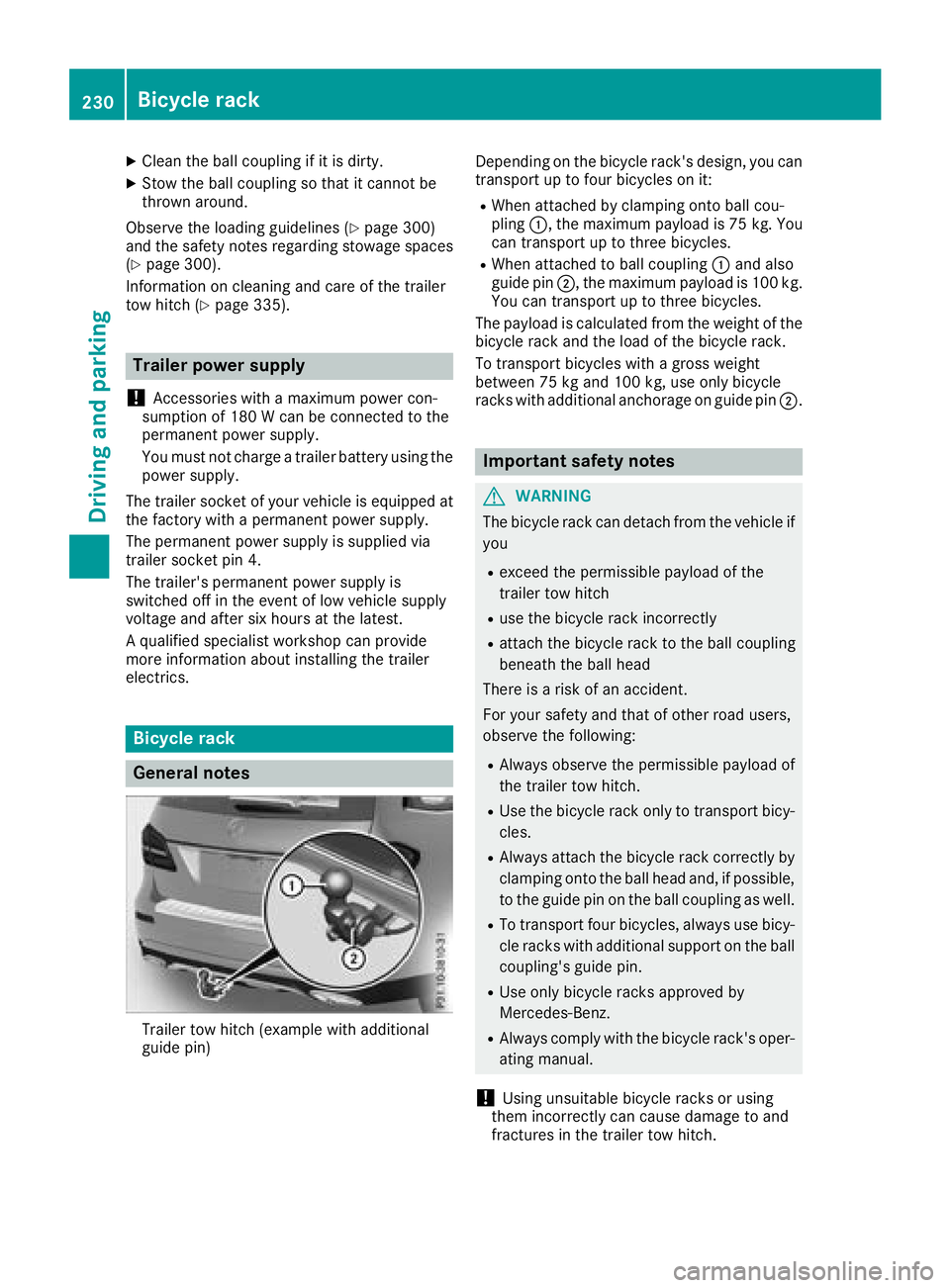
Trailer tow hitch (example withaddit ional
guide pin) Depending on the bicycle rack's design, you can
transport up to four bicycles on it:
RWhen attached by clamping onto ball cou-
pling
:, the maximum payload is 75 kg. You
can transport up to three bicycles.
RWhen attached to ball coupling :and also
guide pin ;, the maximum payload is 100 kg.
You can transport up to three bicycles.
The payload iscalculated from the weight of the
bic ycle rack and the load of the bicycle rack.
To transport bicycles with a gross weight
between 75 kg and 100 kg, use only bicycle
racks with additional anchorage on guide pin ;.
Important safety notes
GWARNING
The bicycle rack can detach from the vehicle if
you
Rexceed the permissible payload of the
trailer tow hitch
Ruse the bicycle rack incorrectly
Rattach the bicycle rack to the ball coupling
beneath the ball head
There is a risk of an accident.
For your safety and that of other road users,
observe the foll owing:
RAlwa ys observe the permissible payload of
the trailer tow hitch.
RUse the bicycle rack only to transport bicy-
cles.
RAlways attach the bicycle rack correctly by
clamping onto the ball head and, if possible,
to the guide pin on the ball coupling as well.
RTo transport four bicycles, always use bicy-
cle racks with additional support on the ball
coupling's guide pin.
RUse only bicycle racks approved by
Mercedes-Benz.
RAlwa ys comply with the bicycle rack's oper-
ating manual.
!Using unsuitab lebicycle racks or using
them incorrectly can cause damage to and
fractures in the trailer tow hitch.
230Bicycle rack
Driving and parking
Page 233 of 398
Use only bicycle racks approved by
Mercedes-Benz.
Bicycle racks cause your vehicle's driving char-
acteristics to change. The vehicle:
Ris heavier
Ris restricted in its acceleration and gradient-
climbing capability
Rhas an increased braking distance This could impair the handling characteristics.
Adapt your driving style accordingly. Maintain a
safe distance and drive carefully.
When using bicycle racks, set the tire pressure
on the rear axle of the vehicle for the maximum
load. Further information on tire pressure can be
found on the tire pressure table (
Ypage 357).
Loading instructions
The greater the distance between the load's center of gravity and the ball head, the higher the load
exerted on the trailer tow hitch.
Therefore, observe the following notes:
RAttach heavy bicycles as close as possible to the vehicle.
RAlways distribute the load on the bicycle rack as symmetrically as possible to the vehicle longi-
tudinal axis.
Before loading the bicycle rack, Mercedes-Benz advises you to remove all add-on parts from the
bicycles, e.g. bicycle baskets, child seats or batteries. This will allow you to improve the aerody-
namic resistance and the bicycle rack's center of gravity.
Always secure bicycles against slipping and check that they are firmly seated at regular intervals.
Do not use tarpaulins or other covers. This could impair the driving characteristics and rear visibility.
The aerodynamic resistance would also rise, and so would the load exerted on the trailer tow hitch
as a result.
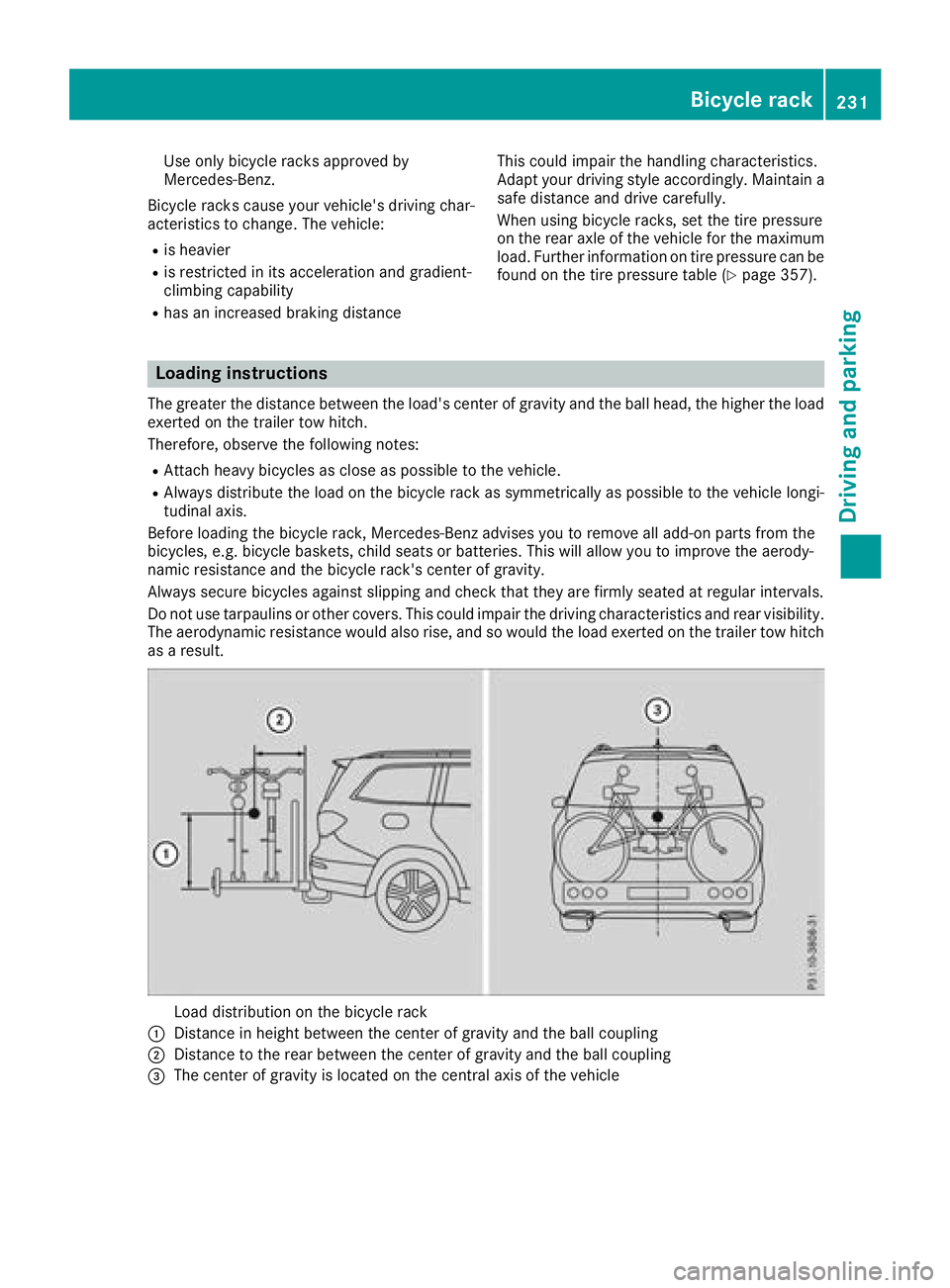
Load distribution on the bicycle rack
:Distance in height between the center of gravity and the ball coupling
;Distance to the rear between the center of gravity and the ball coupling
=The center of gravity is located on the central axis of the vehicle
Bicycle rack231
Driving and parking
Z
Page 234 of 398
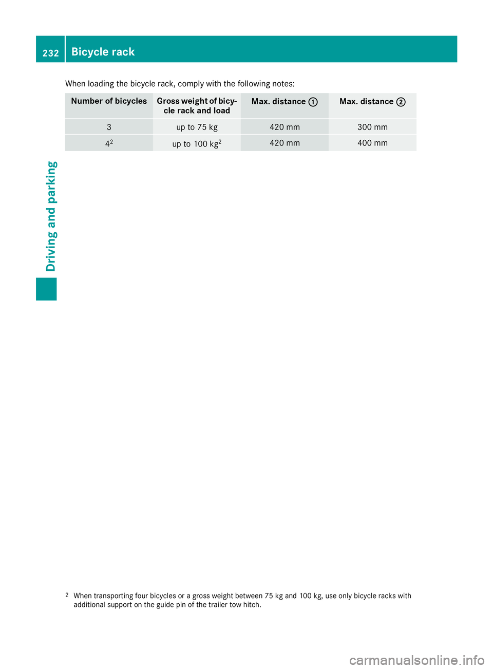
When loading the bicycle rack, comply with the following notes:
Number of bicyclesGross weight of bicy-cle rack and loadMax. distance :Max. distance;
3up to 75 kg420 mm300 mm
42up to 100 kg2420 mm400 mm
2When transporting four bicycles or a gross weight between 75 kg and 100 kg, use only bicycle racks with
additional support on the guide pin of the trailer tow hitch.
232Bicycle rack
Driving and parking
Page 235 of 398
Important safety notes
GWARNING
If you operate information systems and com-
munication equipmen tintegrate din th evehi-
cle when driving ,you may be distracte dfrom
th etraffic situation .You could also lose con-
trol of th evehicle. Ther eis aris kof an acci-
dent.
Only operate this equipmen twhen th etraffic
situation permits. If you are no tsur ethat this
is possible ,park th evehicl epayin gattention
to traffic condition sand operate th eequip-
men twhen th evehicl eis stationary.
You must observ eth elegal requirements for th e
country in whic hyou are currentl ydriving when
operating th eon-board computer.
GWARNIN G
If th einstrumen tcluste rhas faile dor mal-
functioned, you may no trecognize function
restriction sin systems relevan tto safety. The
operating safet yof your vehicl emay be
impaired .Ther eis aris kof an accident.
Drive on carefully. Hav eth evehicl echecke d
at aqualified specialist workshop immedi-
ately.
If th eoperating safet yof your vehicl eis
impaired ,pull ove ras soo nas it is saf eto do so.
Contac t aqualified specialist workshop.
The on-board computer only shows message sor
warning sfrom certain systems in th emultifunc-
tion display. You should therefor emak esur e
your vehicl eis operating safely at all times .
Fo ran overview, see th einstrumen tpanel illus-
tration (
Ypage 37).
Displays and operation
Instrument cluster lighting
The lighting in th einstrumen tcluster, in th edis-
plays and th econtrol sin th evehicl einterior can
be adjusted usin gth ebrightness control knob.
The brightness control knob is locate don th e
botto mleftof th einstrumen tcluste r
(
Ypage 37).
XTurn th ebrightness control knob clockwise or
counter-clockwise.
If you tur nth eligh tswitch to Ã,Tor
L, thebrightness is dependen tupon th e
brightness of th eambien tlight.
iThe ligh tsensor in th einstrumen tcluste r
automatically control sth ebrightness of th e
multifunction display.
In daylight, th edisplays in th einstrumen t
cluste rare no tilluminated.
Speedometer with segments
The segments in th espeedometer indicat e
whic hspee drange is available.
RCruis econtrol activated (Ypage 174):
The segments ligh tup from th estore dspee d
to th emaximum speed.
RDistanc ePilot DISTRONI Cis activated
(Ypage 176):
On eor two segments in th eset spee drange
ligh tup.
RDistanc ePilot DISTRONI Cdetects avehicl ein
fron tmoving mor eslowly than th estore d
speed:
The segments between th espee dof th evehi-
cle in fron tand th estore dspee dligh tup.
Tachometer
!
Do no tdriv ein th eoverrevving range, as this
could damag eth eengine.
The red ban din th etachometer indicates th e
engine's overrevving range.
The fuel suppl yis interrupted to protect th e
engin ewhen th ered ban dis reached.
Outside temperature display
You should pay special attention to road condi-
tion swhen temperatures are aroun dfreezing
point.
Bea rin min dthat th eoutside temperature dis-
play indicates th etemperature measured and
does no trecord th eroad temperature.
The outside temperature display is in th emulti-
function display (
Ypage 235).
Displays and operation233
On-board computer and displays
Z
Page 236 of 398
There is a short delay before a change in outside
temperature appears in the multifunction dis-
play.
Coolant temperature gauge
GWARNING
Opening the hood when the engine is over-
heated or when there is a fire in the engine
compartment could expose you to hot gases
or other service products. There is a risk of
injury.
Let an overheated engine cool down before
opening the hood. If there is a fire in the
engine compartment, keep the hood closed
and contact the fire department.
!If the coolant temperature is too high, a dis-
play message is shown.
If the coolant temperature display is in the
area marked in red, do not continue driving.
Otherwise, the engine will be damaged.
The coolant temperature gauge is in the instru-
ment cluster on the right-hand side (
Ypage 37).
Under normal operating conditions and with the
specified coolant level, the coolant temperature gauge may rise to the red marking.
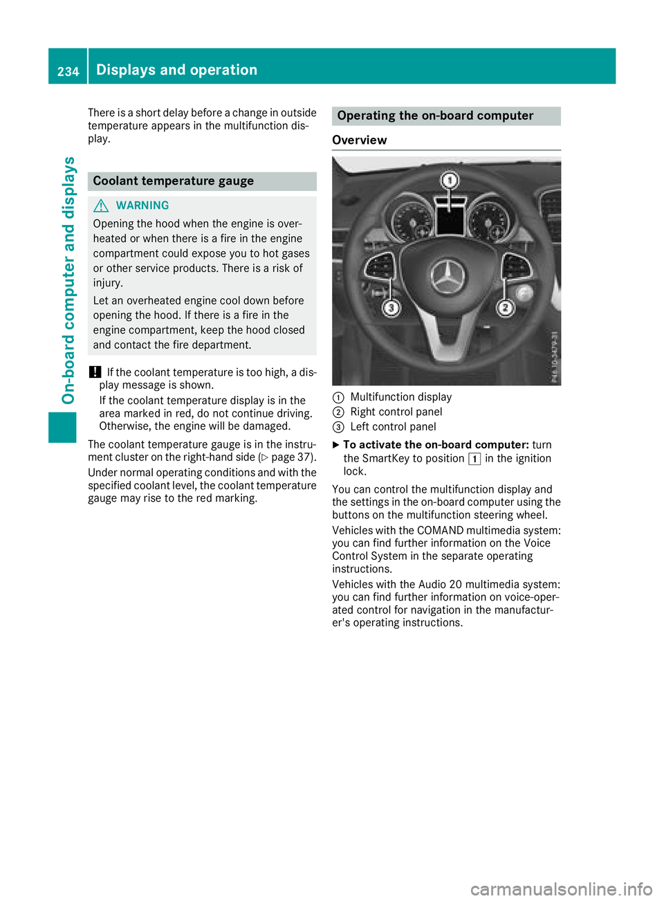
Operating the on-board computer
Overview
:Multifunction display
;Right control panel
=Left control panel
XTo activate the on-board computer: turn
the SmartKey to position 1in the ignition
lock.
You can control the multifunction display and
the settings in the on-board computer using the
buttons on the multifunction steering wheel.
Vehicles with the COMAND multimedia system: you can find further information on the Voice
Control System in the separate operating
instructions.
Vehicles with the Audio 20 multimedia system:
you can find further information on voice-oper-
ated control for navigation in the manufactur-
er's operating instructions.
234Displays and operation
On-board computer and displays
Page 237 of 398
Left control panel
=
;RCalls up the menu and menu bar
9
:Press briefly:
RScrolls in lists
RSelects a submenu or function
RIn theAudiomenu: selects the
previous or next station, when the
preset list or station list is active,
or the previous or next audio track
or video scene
RIn the Tel(Telephone) menu:
switches to the phone book and
selects a name or telephone num-
ber
9
:Press and hold:
RIn the Audiomenu: selects a pre-
set list or a station list in the
desired frequency range or an
audio track or video scene using
rapid scrolling
RIn the Tel(Telephone) menu:
starts rapid scrolling if the phone
book is open
aRConfirms the selection or display
message
RIn the Tel(Telephone) menu:
switches to the phone book and
starts dialing the selected number
%Press briefly:
RBack
RSwitches off voice-operated con-
trol for navigation or the Voice
Control System
RHides display messages or calls up
the last Tripmenu function used
RExits the telephone book/redial
memory
%Press and hold:
RCalls up the standard display in the
Tripmenu
Right control panel
~RRejects or ends a call
RExits the telephone book/redial
memory
6RMakes or accepts a call
RSwitches to the redial memory
W
XRAdjusts the volume
8RMute
?RSwitches on voice-operated con-
trol for navigation or the Voice
Control System
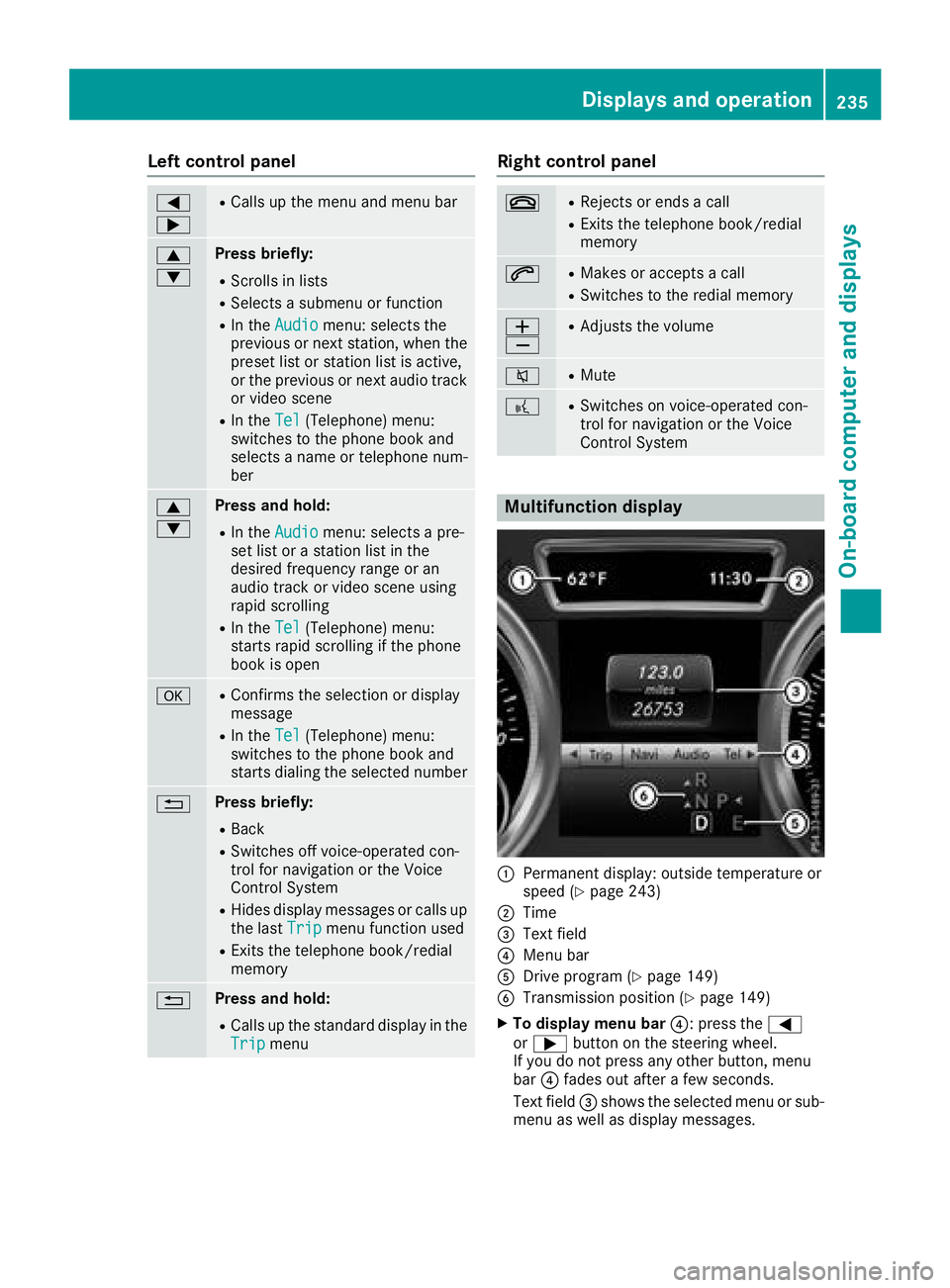
Multifunction display
:Permanent display: outside temperature or
speed (Ypage 243)
;Time
=Text field
?Menu bar
ADrive program (Ypage 149)
BTransmission position (Ypage 149)
XTo display menu bar ?: press the=
or ; button on the steering wheel.
If you do not press any other button, menu
bar ?fades out after a few seconds.
Text field =shows the selected menu or sub-
menu as well as display messages.
Displays and operation235
On-board computer and displays
Z
Page 238 of 398
iSet the time using the multimedia system;
see the Digital Operator's Manual.
Possible displays in the multifunction dis-
play:
RZ Gearshift recommendation, when shifting
manually (Ypage 152)
Rj Parking Pilot (Ypage 195)
RCRUISECruise control (Ypage 174)
R_ Adaptive Highbeam Assist
(Ypage 118)
Rè ECO start/stop function (Ypage 144)
RëHOLD function (Ypage 187)
RaDistance Pilot DISTRONIC Steering Pilot
(Ypage 241)
RDSRDownhill Speed Regulation
(Ypage 218)
Menus and submenus
Menu overview
Press the =or; button on the steering
wheel to call up the menu bar and select a menu.
Operating the on-board computer (
Ypage 234).
Depending on the equipment installed in the
vehicle, you can call up the following menus:
RTripmenu (Ypage 236)
RNavimenu (navigation instructions)
(Ypage 237)
RAudiomenu (Ypage 239)
RTelmenu (telephone) (Ypage 240)
RDriveAssistmenu (assistance)
(Ypage 241)
RServ.menu (Ypage 242)
RSett.menu (settings) (Ypage 243)
RON&OFFROADmenu (Ypage 245)
RAMGmenu (Mercedes-AMG vehicles)
(Ypage 245)
Trip menu
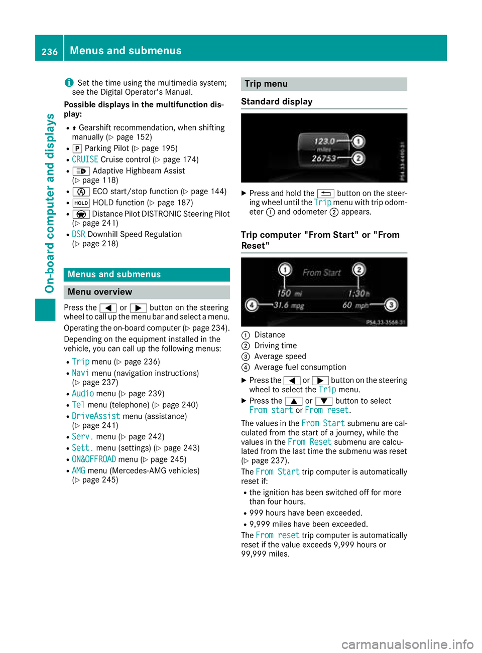
Standard display
XPress and hold the %button on the steer-
ing wheel until the Tripmenu with trip odom-
eter :and odometer ;appears.
Trip computer "From Start" or "From
Reset"
:Distance
;Driving time
=Average speed
?Average fuel consumption
XPress the =or; button on the steering
wheel to select the Tripmenu.
XPress the9or: button to select
From startor From reset.
The values in the From
Startsubmenu are cal-
culated from the start of a journey, while the
values in the From Reset
submenu are calcu-
lated from the last time the submenu was reset
(
Ypage 237).
The From Start
trip computer is automatically
reset if:
Rthe ignition has been switched off for more
than four hours.
R999 hours have been exceeded.
R9,999 miles have been exceeded.
The From reset
trip computer is automatically
reset if the value exceeds 9,999 hours or
99,999 miles.
236Menus and submenus
On-board computer and displays
Page 239 of 398

ECO display
The ECO display is not available for Mercedes-
AMG vehicles.
XPress the=or; button on the steering
wheel to select the Tripmenu.
XPress the9or: button to select ECODISPLAY.
If the ignition remains switched off for longer
than four hours, the ECO display will be auto-
matically reset.
For more information on the ECO display, see
(
Ypage 165).
Displaying the range and current fuel
consumption
Mercedes-AMG vehicles: the menu displays
only the approximate range :.
XPress the=or; button on the steering
wheel to select the Tripmenu.
Digital speedometer
XPress the=or; button on the steering
wheel to select the Tripmenu.
XPress the9or: button to select the
digital speedometer.
A gear shift recommendation Zcan also
appear.
Observe the information on gearshift recom-
mendation Zwhen shifting manually
(
Ypage 152).
Mercedes-AMG vehicles: a gearshift recom-
mendation is shown in the status bar of the
multifunction display and not in the digital
speedometer display.
Resetting values
XPress the =or; button on the steering
wheel to select the Tripmenu.
XPress the9or: button to select the
function that you wish to reset.
XPress ato confirm your selection.
XPress :to select Yesand press ato
confirm.
You can reset the values of the following func-
tions:
RTrip odometer
R"From Start" trip computer
R"From Reset" trip computer
RECO display
If you reset the values in the ECO display, the
values in the "From Start" trip computer are also reset. If you reset the values in the "From Start"
trip computer, the values in the ECO display are
also reset.
Navigation system menu
Displaying navigation instructions
In the Navimenu, the multifunction display
shows navigation instructions.
You can find further information on navigation in
the Digital Operator's Manual in the multimedia
system.
XSwitch on the multimedia system (see the
Digital Operator's Manual)
XPress the =or; button on the steering
wheel to select the Navimenu.
Route guidance not active
:Direction of travel
;Current road
Menus and submenus237
On-board computer and displays
Z
Page 240 of 398
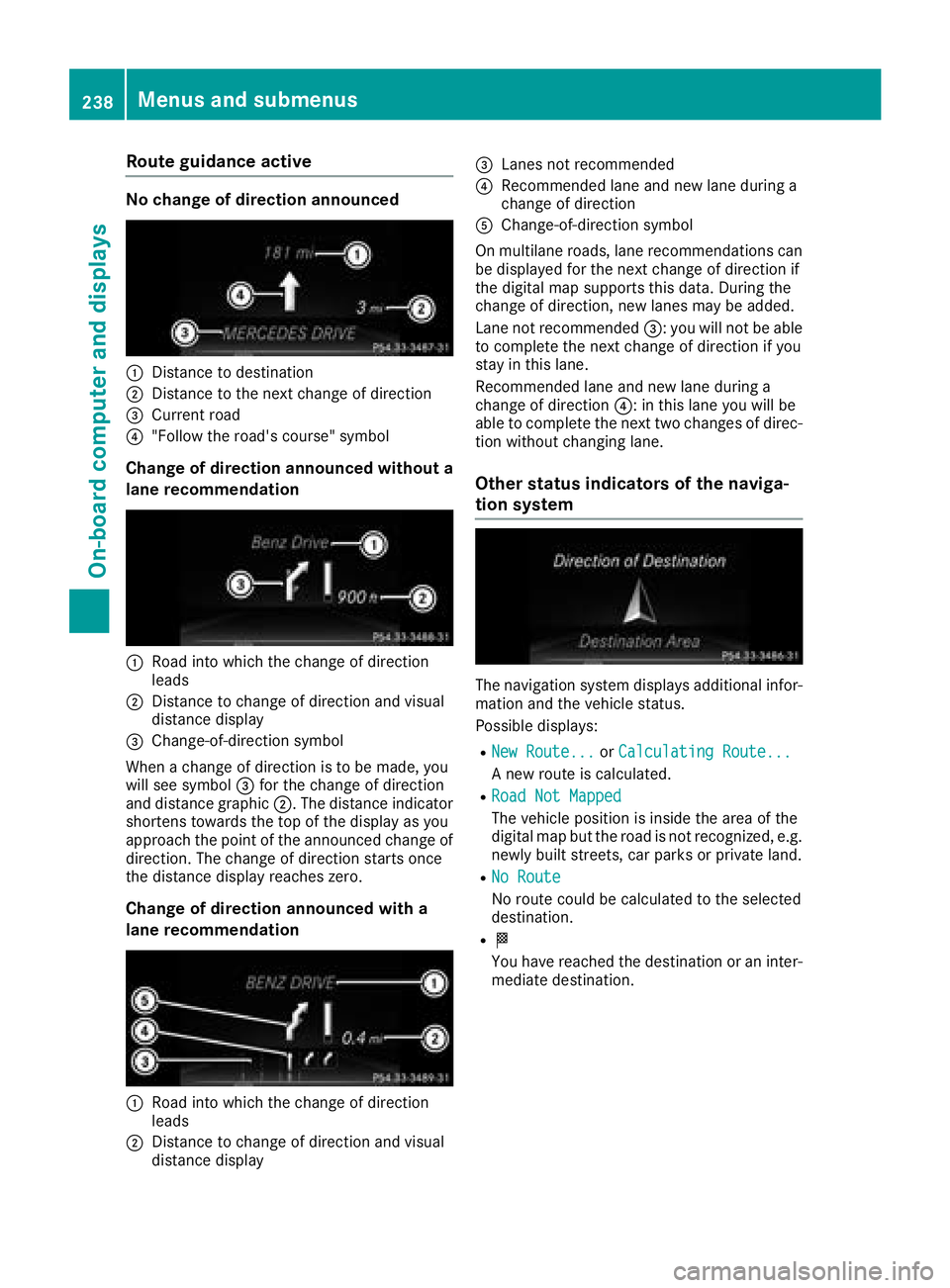
Route guidance active
No change of direction announced
:Distance to destination
;Distance to the next change of direction
=Current road
?"Follow the road's course" symbol
Change of direction announced without a
lane recommendation
:Road into which the change of direction
leads
;Distance to change of direction and visual
distance display
=Change-of-direction symbol
When a change of direction is to be made, you
will see symbol =for the change of direction
and distance graphic ;. The distance indicator
shortens towards the top of the display as you
approach the point of the announced change of
direction. The change of direction starts once
the distance display reaches zero.
Change of direction announced with a
lane recommendation
:Road into which the change of direction
leads
;Distance to change of direction and visual
distance display
=Lanes not recommended
?Recommended lane and new lane during a
change of direction
AChange-of-direction symbol
On multilane roads, lane recommendations can
be displayed for the next change of direction if
the digital map supports this data. During the
change of direction, new lanes may be added.
Lane not recommended =: you will not be able
to complete the next change of direction if you
stay in this lane.
Recommended lane and new lane during a
change of direction ?: in this lane you will be
able to complete the next two changes of direc-
tion without changing lane.
Other status indicators of the naviga-
tion system
The navigation system displays additional infor-
mation and the vehicle status.
Possible displays:
RNew Route...or Calculating Route...
A new route is calculated.
RRoad Not Mapped
The vehicle position is inside the area of the
digital map but the road is not recognized, e.g.
newly built streets, car parks or private land.
RNo Route
No route could be calculated to the selected
destination.
RO
You have reached the destination or an inter-
mediate destination.
238Menus and submenus
On-board computer and displays