air condition MERCEDES-BENZ ML320 1997 Complete Repair Manual
[x] Cancel search | Manufacturer: MERCEDES-BENZ, Model Year: 1997, Model line: ML320, Model: MERCEDES-BENZ ML320 1997Pages: 4133, PDF Size: 88.89 MB
Page 3377 of 4133
ENGINE 111, 112, 271, 272, 611, 612, 646 in MODEL 203.7 with CODE (580) Air conditioning (or
Tempmatic for USA) with CODE (580) Automatic air conditioning with CODE (581) Automatic air
conditioning with CODE (581) Comfort automatic air conditioning
ENGINE 112.942 /970, 113.942 /965 /981, 612.963, 628.963 in MODEL 163 as of 1.9.01 with CODE (580)
Automatic air conditioning
ENGINE 112, 113, 271, 272, 273, 612, 642, 646 in MODEL 209.3
ENGINE 112, 113, 271, 272, 273, 642 in MODEL 209.4
Shown on model 203
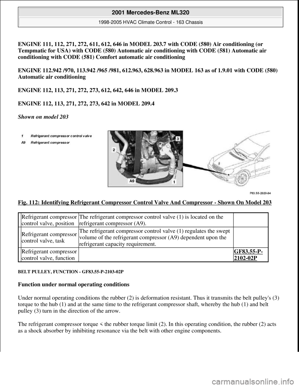
Fig. 112: Identifying Refrigerant Compressor Control Valve And Compressor
- Shown On Model 203
BELT PULLEY, FUNCTION - GF83.55-P-2103-02P
Function under normal operating conditions
Under normal operating conditions the rubber (2) is deformation resistant. Thus it transmits the belt pulley's (3)
torque to the hub (1) and at the same time to the refrigerant compressor shaft, whereby the hub (1) and belt
pulley (3) turn in the direction of the arrow.
The refrigerant compressor torque < the rubber torque limit (2). In this operating condition, the rubber (2) acts
as a shock absorber b
y inhibiting resonance via the belt with other engine components.
Refrigerant compressor
control valve, positionThe refrigerant compressor control valve (1) is located on the
refrigerant compressor (A9).
Refrigerant compressor
control valve, taskThe refrigerant compressor control valve (1) regulates the swept
volume of the refrigerant compressor (A9) dependent upon the
refrigerant capacity requirement.
Refrigerant compressor
control valve, function GF83.55-P-
2102-02P
2001 Mercedes-Benz ML320
1998-2005 HVAC Climate Control - 163 Chassis
me
Saturday, October 02, 2010 3:23:17 PMPage 133 © 2006 Mitchell Repair Information Company, LLC.
Page 3378 of 4133
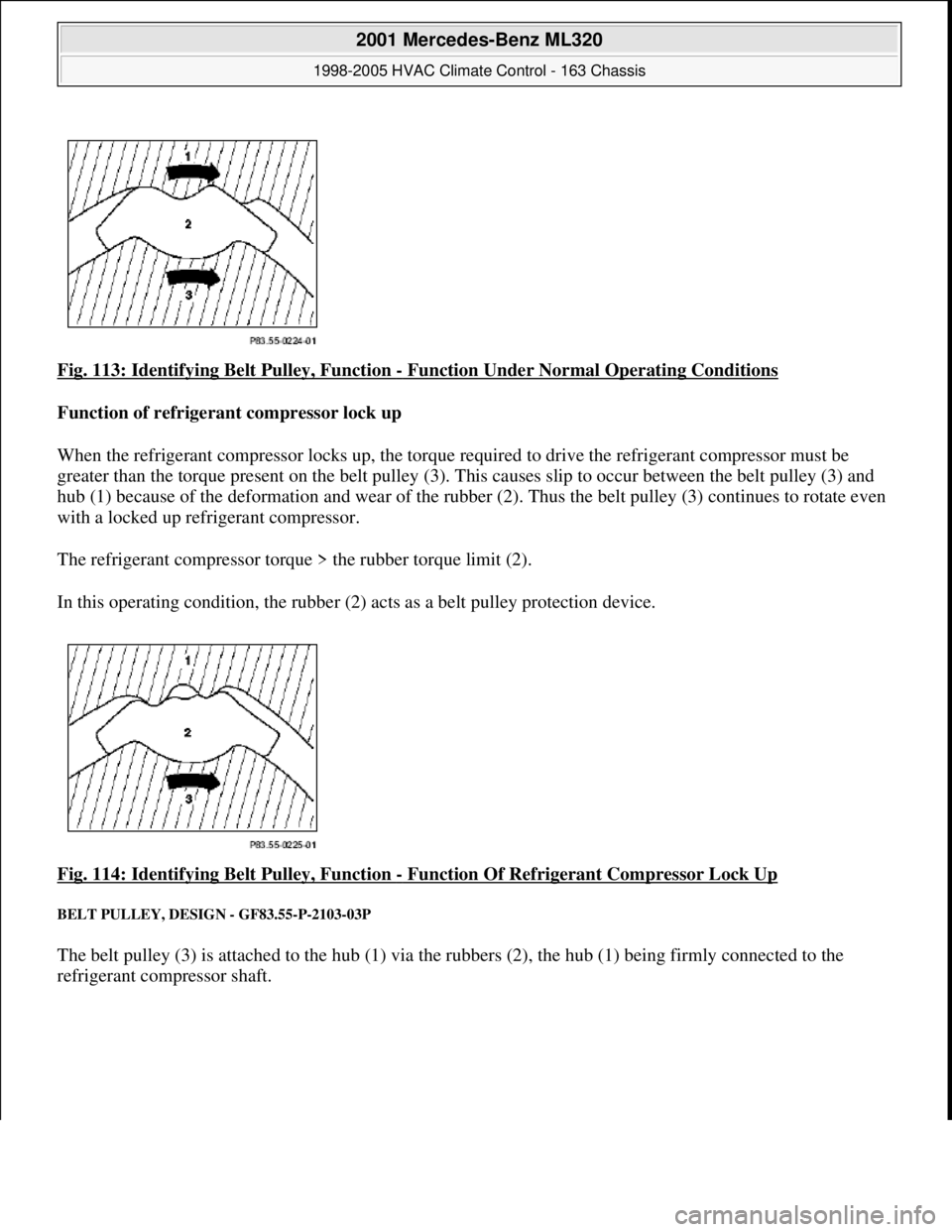
Fig. 113: Identifying Belt Pulley, Function - Function Under Normal Operating Conditions
Function of refrigerant compressor lock up
When the refrigerant compressor locks up, the torque re quired to drive the refrigerant compressor must be
greater than the torque present on the belt pulley (3). Th is causes slip to occur between the belt pulley (3) and
hub (1) because of the deformation and w ear of the rubber (2). Thus the belt pulley (3) continues to rotate even
with a locked up refrigerant compressor.
The refrigerant compressor torque > the rubber torque limit (2).
In this operating condition, the rubber (2) acts as a belt pulley protection device.
Fig. 114: Identifying Belt Pulley, Function
- Function Of Refrigerant Compressor Lock Up
BELT PULLEY, DESIGN - GF83.55-P-2103-03P
The belt pulley (3) is attached to the hub (1) via the rubbers (2), the hub (1) being firmly connected to the
refrigerant compressor shaft.
2001 Mercedes-Benz ML320
1998-2005 HVAC Climate Control - 163 Chassis
me
Saturday, October 02, 2010 3:23:17 PMPage 134 © 2006 Mitchell Repair Information Company, LLC.
Page 3379 of 4133
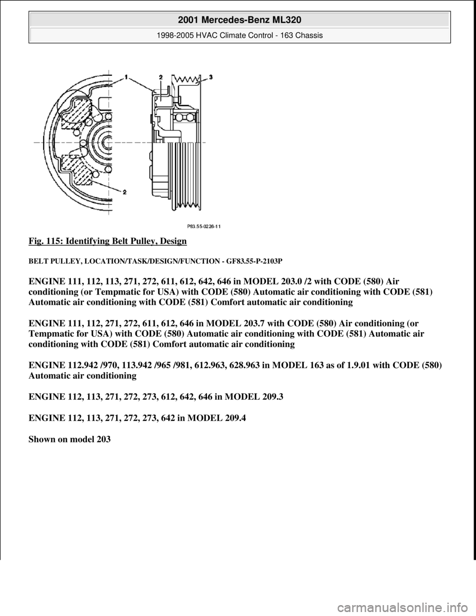
Fig. 115: Identifying Belt Pulley, Design
BELT PULLEY, LOCATION/TASK/DESIGN/FUNCTION - GF83.55-P-2103P
ENGINE 111, 112, 113, 271, 272, 611, 612, 642, 646 in MODEL 203.0 /2 with CODE (580) Air
conditioning (or Tempmatic for USA) with CODE (580) Automatic air conditioning with CODE (581)
Automatic air conditioning with CODE (581) Comfort automatic air conditioning
ENGINE 111, 112, 271, 272, 611, 612, 646 in MODEL 203.7 with CODE (580) Air conditioning (or
Tempmatic for USA) with CODE (580) Automatic air conditioning with CODE (581) Automatic air
conditioning with CODE (581) Comfort automatic air conditioning
ENGINE 112.942 /970, 113.942 /965 /981, 612.963, 628.963 in MODEL 163 as of 1.9.01 with CODE (580)
Automatic air conditioning
ENGINE 112, 113, 271, 272, 273, 612, 642, 646 in MODEL 209.3
ENGINE 112, 113, 271, 272, 273, 642 in MODEL 209.4
Shown on model 203
2001 Mercedes-Benz ML320
1998-2005 HVAC Climate Control - 163 Chassis
me
Saturday, October 02, 2010 3:23:17 PMPage 135 © 2006 Mitchell Repair Information Company, LLC.
Page 3380 of 4133
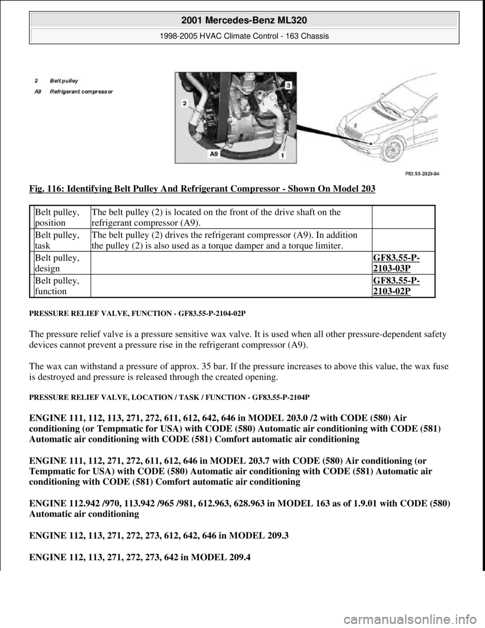
Fig. 116: Identifying Belt Pulley And Refrigerant Compressor - Shown On Model 203
PRESSURE RELIEF VALVE, FUNCTION - GF83.55-P-2104-02P
The pressure relief valve is a pressure sensitive wax valve. It is used when all other pressure-dependent safety
devices cannot prevent a pressure rise in the refrigerant compressor (A9).
The wax can withstand a pressure of approx. 35 bar. If the pressure increases to above this value, the wax fuse
is destroyed and pressure is released through the created opening.
PRESSURE RELIEF VALVE, LOCATION / TASK / FUNCTION - GF83.55-P-2104P
ENGINE 111, 112, 113, 271, 272, 611, 612, 642, 646 in MODEL 203.0 /2 with CODE (580) Air
conditioning (or Tempmatic for USA) with CODE (580) Automatic air conditioning with CODE (581)
Automatic air conditioning with CODE (581) Comfort automatic air conditioning
ENGINE 111, 112, 271, 272, 611, 612, 646 in MODEL 203.7 with CODE (580) Air conditioning (or
Tempmatic for USA) with CODE (580) Automatic air conditioning with CODE (581) Automatic air
conditioning with CODE (581) Comfort automatic air conditioning
ENGINE 112.942 /970, 113.942 /965 /981, 612.963, 628.963 in MODEL 163 as of 1.9.01 with CODE (580)
Automatic air conditioning
ENGINE 112, 113, 271, 272, 273, 612, 642, 646 in MODEL 209.3
ENGINE 112, 113, 271, 272, 273, 642 in MODEL 209.4
Belt pulley,
positionThe belt pulley (2) is located on the front of the drive shaft on the
refrigerant compressor (A9).
Belt pulley,
taskThe belt pulley (2) drives the refrigerant compressor (A9). In addition
the pulley (2) is also used as a torque damper and a torque limiter.
Belt pulley,
design GF83.55-P-
2103-03P
Belt pulley,
function GF83.55-P-
2103-02P
2001 Mercedes-Benz ML320
1998-2005 HVAC Climate Control - 163 Chassis
me
Saturday, October 02, 2010 3:23:17 PMPage 136 © 2006 Mitchell Repair Information Company, LLC.
Page 3381 of 4133

Shown on model 203
Fig. 117: Identifying Pressure Relief Valve And Refrigerant Compressor
- Shown On Model 203
TEMPERATURE CONTROL, FUNCTION - GF83.57-P-2000GH
MODEL 163 up to 31.08.01 with CODE (580) Air conditioning or Tempmatic for USA
Function
The temperature preselected at the temperature selector wheels is reached or kept constant by:
heating up by the heat exchanger,
heating up by the electric heater booster (with engine 612.963 only)
cooling by the evaporator core,
cooling and reheating (reheat mode).
Heating up
The heating system heat exchanger heats the air passing by, which is then conducted into the vehicle interior by
the air ducts.
Heating up by the electric heater booster
Due to the high level of efficiency of the direct-injection diesel engine, the heat output of the coolant is not
sufficient to heat the fresh air. By installing the electric heater booster, behind the heating system heat
exchanger, this heating capacity deficit is compensated.
Pressure relief
valve, positionThe pressure relief valve (3) is located on the refrigerant
compressor (A9).
Pressure relief
valve, taskThe pressure relief valve (3) serves to protect the refrigerant
circuit from damage caused by excess pressure.
Pressure relief
valve, function GF83.55-P-
2104-02P
2001 Mercedes-Benz ML320
1998-2005 HVAC Climate Control - 163 Chassis
me
Saturday, October 02, 2010 3:23:17 PMPage 137 © 2006 Mitchell Repair Information Company, LLC.
Page 3382 of 4133
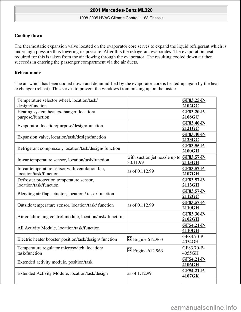
Cooling down
The thermostatic expansion valve located on the evaporator core serves to expand the liquid refrigerant which is
under high pressure thus lowering its pressure. After this the refrigerant evaporates. The evaporation heat
required for this is taken from the air flowing through the evaporator. The resulting cooled down air then
succeeds in entering the passenger compartment via the air ducts.
Reheat mode
The air which has been cooled down and dehumidified by the evaporator core is heated up again by the heat
exchanger (reheat). This serves to prevent the windows from misting up on the inside.
Temperature selector wheel, location/task/
design/function GF83.25-P-
2102GC
Heating system heat exchanger, location/
purpose/function GF83.20-P-
2108GC
Evaporator, location/purpose/design/function GF83.40-P-
2121GC
Expansion valve, location/task/design/function GF83.40-P-
2123GC
Refrigerant compressor, location/task/design/ function GF83.55-P-
2100GH
In-car temperature sensor, location/task/functionwith suction jet nozzle up to
30.11.99GF83.57-P-
2115GH
In-car temperature sensor with ventilation fan,
location/task/functionas of 01.12.99GF83.57-P-
2107GH
Defroster protection temperature sensor,
location/task/function GF83.57-P-
2113GH
Blending air flap actuator, location / task / function GF83.57-P-
2112GC
Outside temperature sensor, location/task/ functionas of 01.12.99GF83.57-P-
2110GH
Air conditioning control module, location/task/ function GF83.30-P-
2102GH
All Activity Module, location/task/function GF54.21-P-
4110GH
Electric heater booster position/task/design/ function Engine 612.963GF83.70-P-
4054GH
Temperature regulator microswitch, location/
task/function Engine 612.963GF83.70-P-
4055GH
Extended activity module, position/task GF54.21-P-
4106GH
Extended Activity Module, location/task/designas of 1.12.99GF54.21-P-
4107GK
2001 Mercedes-Benz ML320
1998-2005 HVAC Climate Control - 163 Chassis
me
Saturday, October 02, 2010 3:23:17 PMPage 138 © 2006 Mitchell Repair Information Company, LLC.
Page 3383 of 4133
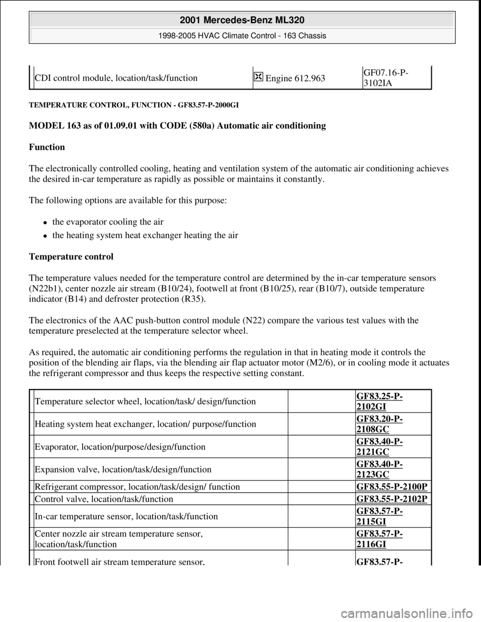
TEMPERATURE CONTROL, FUNCTION - GF83.57-P-2000GI
MODEL 163 as of 01.09.01 with CODE (580a) Automatic air conditioning
Function
The electronically controlled cooling, heating and ventilation system of the automatic air conditioning achieves
the desired in-car temperature as rapidly as possible or maintains it constantly.
The following options are available for this purpose:
the evaporator cooling the air
the heating system heat exchanger heating the air
Temperature control
The temperature values needed for the temperature control are determined by the in-car temperature sensors
(N22b1), center nozzle air stream (B10/24), footwell at front (B10/25), rear (B10/7), outside temperature
indicator (B14) and defroster protection (R35).
The electronics of the AAC push-button control module (N22) compare the various test values with the
temperature preselected at the temperature selector wheel.
As required, the automatic air conditioning performs the regulation in that in heating mode it controls the
position of the blending air flaps, via the blending air flap actuator motor (M2/6), or in cooling mode it actuates
the refrigerant compressor and thus keeps the respective setting constant.
CDI control module, location/task/function Engine 612.963GF07.16-P-
3102IA
Temperature selector wheel, location/task/ design/function GF83.25-P-
2102GI
Heating system heat exchanger, location/ purpose/function GF83.20-P-
2108GC
Evaporator, location/purpose/design/function GF83.40-P-
2121GC
Expansion valve, location/task/design/function GF83.40-P-
2123GC
Refrigerant compressor, location/task/design/ function GF83.55-P-2100P
Control valve, location/task/function GF83.55-P-2102P
In-car temperature sensor, location/task/function GF83.57-P-
2115GI
Center nozzle air stream temperature sensor,
location/task/function GF83.57-P-
2116GI
Front footwell air stream temperature sensor, GF83.57-P-
2001 Mercedes-Benz ML320
1998-2005 HVAC Climate Control - 163 Chassis
me
Saturday, October 02, 2010 3:23:17 PMPage 139 © 2006 Mitchell Repair Information Company, LLC.
Page 3385 of 4133
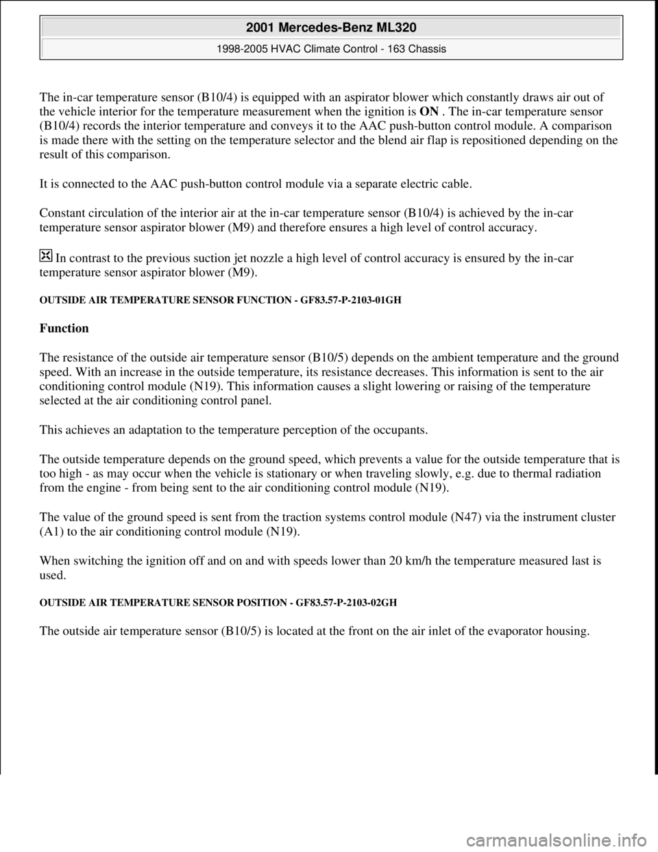
The in-car temperature sensor (B10/4) is equipped with an aspirator blower which constantly draws air out of
the vehicle interior for the temperature measurement when the ignition is ON . The in-car temperature sensor
(B10/4) records the interior temperature and conveys it to the AAC push-button control module. A comparison
is made there with the setting on the temperature selector and the blend air flap is repositioned depending on the
result of this comparison.
It is connected to the AAC push-button control module via a separate electric cable.
Constant circulation of the interior air at the in-car temperature sensor (B10/4) is achieved by the in-car
temperature sensor aspirator blower (M9) and therefore ensures a high level of control accuracy.
In contrast to the previous suction jet nozzle a high level of control accuracy is ensured by the in-car
temperature sensor aspirator blower (M9).
OUTSIDE AIR TEMPERATURE SENSOR FUNCTION - GF83.57-P-2103-01GH
Function
The resistance of the outside air temperature sensor (B10/5) depends on the ambient temperature and the ground
speed. With an increase in the outside temperature, its resistance decreases. This information is sent to the air
conditioning control module (N19). This information causes a slight lowering or raising of the temperature
selected at the air conditioning control panel.
This achieves an adaptation to the temperature perception of the occupants.
The outside temperature depends on the ground speed, which prevents a value for the outside temperature that is
too high - as may occur when the vehicle is stationary or when traveling slowly, e.g. due to thermal radiation
from the engine - from being sent to the air conditioning control module (N19).
The value of the ground speed is sent from the traction systems control module (N47) via the instrument cluster
(A1) to the air conditioning control module (N19).
When switching the ignition off and on and with speeds lower than 20 km/h the temperature measured last is
used.
OUTSIDE AIR TEMPERATURE SENSOR POSITION - GF83.57-P-2103-02GH
The outside air temperature sensor (B10/5) is located at the front on the air inlet of the evaporator housing.
2001 Mercedes-Benz ML320
1998-2005 HVAC Climate Control - 163 Chassis
me
Saturday, October 02, 2010 3:23:17 PMPage 141 © 2006 Mitchell Repair Information Company, LLC.
Page 3386 of 4133
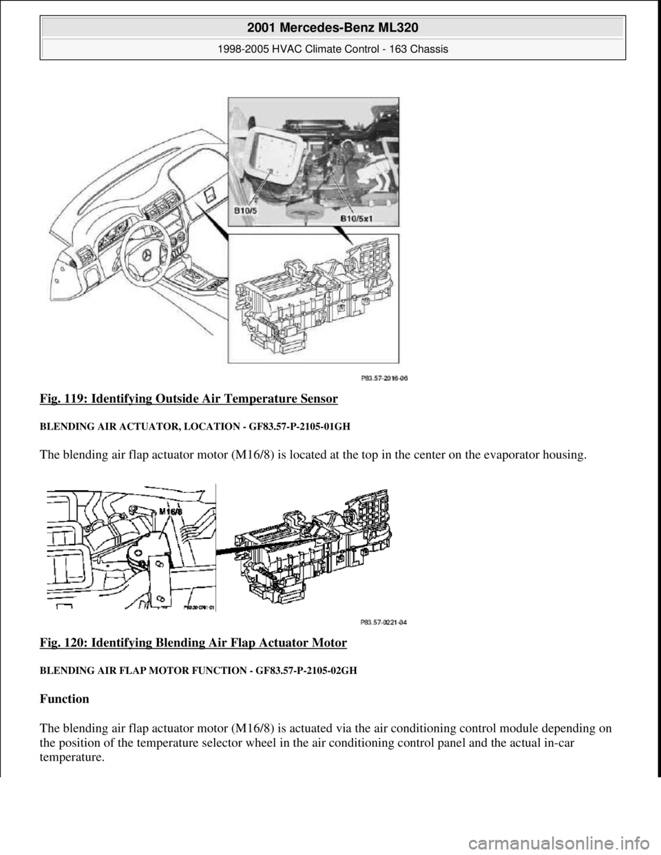
Fig. 119: Identifying Outsid e Air Temperature Sensor
BLENDING AIR ACTUATOR, LOCATION - GF83.57-P-2105-01GH
The blending air flap actuator motor (M16/8) is located at the top in the center on the evaporator housing.
Fig. 120: Identifying Blending Air Flap Actuator Motor
BLENDING AIR FLAP MOTOR FUNCTION - GF83.57-P-2105-02GH
Function
The blending air flap actuator motor (M16/8) is actu ated via the air conditioning control module depending on
the position of the temperature sel ector wheel in the air conditioning co ntrol panel and the actual in-car
temperature.
2001 Mercedes-Benz ML320
1998-2005 HVAC Climate Control - 163 Chassis
me
Saturday, October 02, 2010 3:23:17 PMPage 142 © 2006 Mitchell Repair Information Company, LLC.
Page 3387 of 4133
The mechanical flaps are regulated by a linkage to the blending air flap actuator motor (M16/8). The flaps open
or close the passage of air through the heating system heat exchanger in order to mix heated air with cooled air
in the correct proportion necessary to achieve the desired in-car temperature.
The set point flap angle of the blending air flaps is determined by the air conditioning control module as a
function of the following information:
set point temperature selected at the temperature selector wheel
in-car temperature measured at the in-car temperature sensor (B10/4)
BLENDING AIR FLAP MOTOR FUNCTION - GF83.57-P-2105-02GI
Function
The blending air flap actuator motor (M2/6) is actuated via the AC bus and as a function of the position of the
temperature selector wheel in the AAC push-button control module (N22) and the actual in-car temperature.
The mechanical flaps are regulated by a linkage to the blending air flap actuator motor (M2/6). The flaps open
or close the passage of air through the heating system heat exchanger in order to mix heated air with cooled air
in the correct proportion necessary to achieve the desired in-car temperature.
The set point flap angle of the blending air flaps is determined by the AAC push-button control module (N22)
as a function of the following information:
set point temperature selected at the temperature selector wheel
in-car temperature measured at the in-car temperature sensor (N22b1)
temperatures of the air stream measured at the center nozzle air stream temperature sensors, footwell
forward and rear (B10/24, B10/25 and B10/7)
outside temperature measured by the outside temperature indicator temperature sensor (B14)
All actuators are identical.
If a problem exists, it is possible to retrieve and verify the defined end positions by means of the diagnosis
assistant system (DAS) (valuation trip).
After an actuator motor has been replaced, an adjustment run must be performed via the Diagnosis Assistant
System (DAS), i.e. the end positions flap OPEN and SHUT are defined and retained.
ICING PROTECTION TEMPERATURE SENSOR, LOCATION - GF83.57-P-2106-01GH
The icing protection temperature sensor (R35) is located at the center rear of the evaporator housing.
2001 Mercedes-Benz ML320
1998-2005 HVAC Climate Control - 163 Chassis
me
Saturday, October 02, 2010 3:23:17 PMPage 143 © 2006 Mitchell Repair Information Company, LLC.