air condition MERCEDES-BENZ ML320 1997 Complete Repair Manual
[x] Cancel search | Manufacturer: MERCEDES-BENZ, Model Year: 1997, Model line: ML320, Model: MERCEDES-BENZ ML320 1997Pages: 4133, PDF Size: 88.89 MB
Page 3364 of 4133
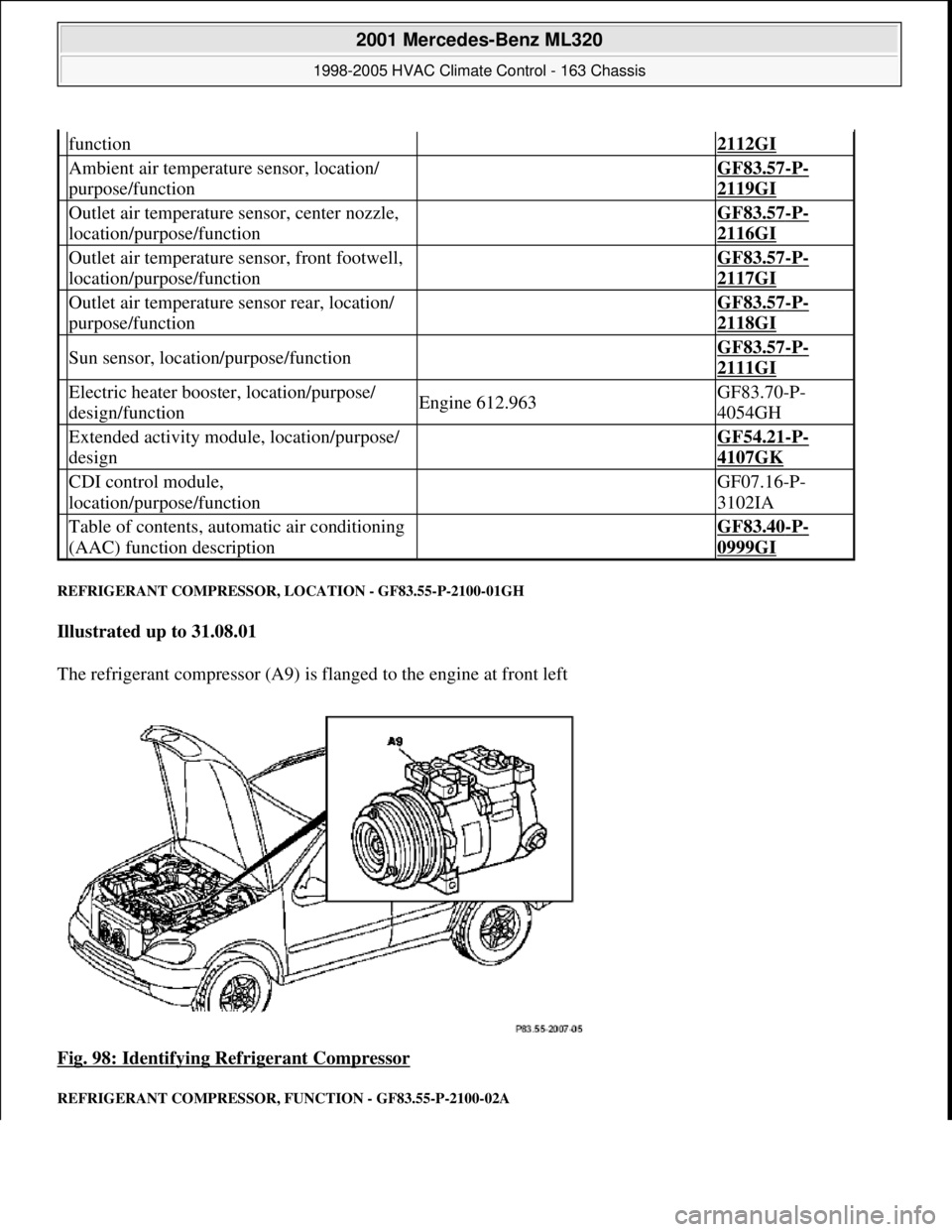
REFRIGERANT COMPRESSOR, LOCATION - GF83.55-P-2100-01GH
Illustrated up to 31.08.01
The refrigerant compressor (A9) is flanged to the engine at front left
Fig. 98: Identifying Refrigerant Compressor
REFRIGERANT COMPRESSOR, FUNCTION - GF83.55-P-2100-02A
function2112GI
Ambient air temperature sensor, location/
purpose/function GF83.57-P-
2119GI
Outlet air temperature sensor, center nozzle,
location/purpose/function GF83.57-P-
2116GI
Outlet air temperature sensor, front footwell,
location/purpose/function GF83.57-P-
2117GI
Outlet air temperature sensor rear, location/
purpose/function GF83.57-P-
2118GI
Sun sensor, location/purpose/function GF83.57-P-
2111GI
Electric heater booster, location/purpose/
design/functionEngine 612.963GF83.70-P-
4054GH
Extended activity module, location/purpose/
design GF54.21-P-
4107GK
CDI control module,
location/purpose/function GF07.16-P-
3102IA
Table of contents, automatic air conditioning
(AAC) function description GF83.40-P-
0999GI
2001 Mercedes-Benz ML320
1998-2005 HVAC Climate Control - 163 Chassis
me
Saturday, October 02, 2010 3:23:16 PMPage 120 © 2006 Mitchell Repair Information Company, LLC.
Page 3365 of 4133
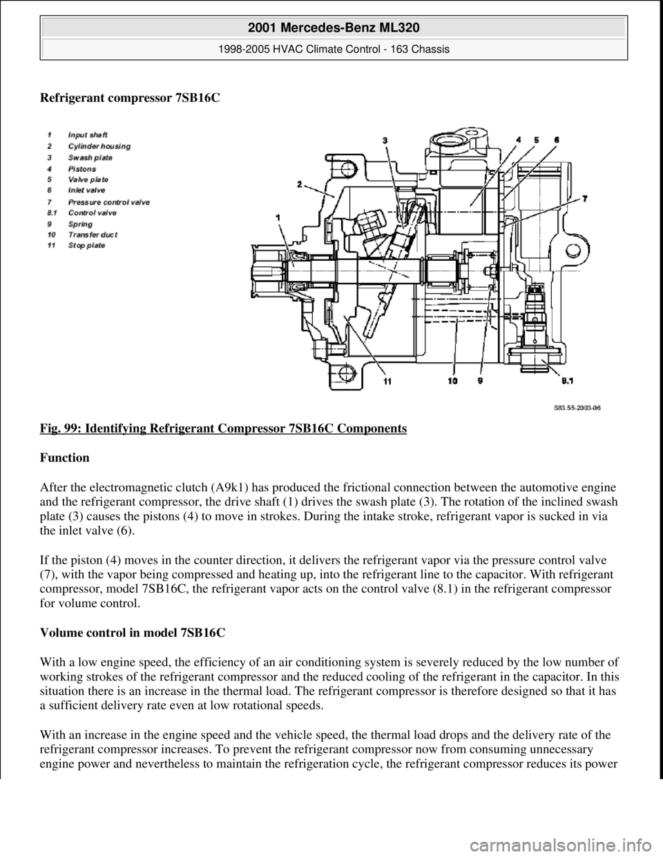
Refrigerant compressor 7SB16C
Fig. 99: Identifying Refrigerant Compressor 7SB16C Components
Function
After the electromagnetic clutch (A9k1) has produced the frictional connection between the automotive engine
and the refrigerant compressor, the drive shaft (1) drives the swash plate (3). The rotation of the inclined swash
plate (3) causes the pistons (4) to move in strokes. During the intake stroke, refrigerant vapor is sucked in via
the inlet valve (6).
If the piston (4) moves in the counter direction, it delivers the refrigerant vapor via the pressure control valve
(7), with the vapor being compressed and heating up, into the refrigerant line to the capacitor. With refrigerant
compressor, model 7SB16C, the refrigerant vapor acts on the control valve (8.1) in the refrigerant compressor
for volume control.
Volume control in model 7SB16C
With a low engine speed, the efficiency of an air conditioning system is severely reduced by the low number of
working strokes of the refrigerant compressor and the reduced cooling of the refrigerant in the capacitor. In this
situation there is an increase in the thermal load. The refrigerant compressor is therefore designed so that it has
a sufficient delivery rate even at low rotational speeds.
With an increase in the engine speed and the vehicle speed, the thermal load drops and the delivery rate of the
refrigerant compressor increases. To prevent the refrigerant compressor now from consuming unnecessary
en
gine power and nevertheless to maintain the refrigeration cycle, the refrigerant compressor reduces its power
2001 Mercedes-Benz ML320
1998-2005 HVAC Climate Control - 163 Chassis
me
Saturday, October 02, 2010 3:23:16 PMPage 121 © 2006 Mitchell Repair Information Company, LLC.
Page 3366 of 4133
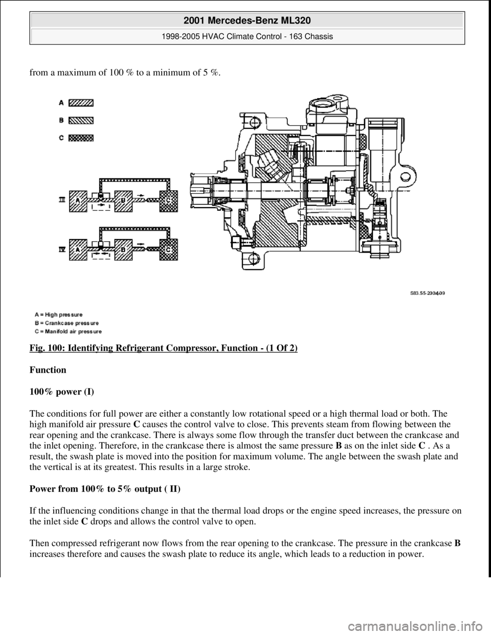
from a maximum of 100 % to a minimum of 5 %.
Fig. 100: Identifying Refrigerant Compressor, Function
- (1 Of 2)
Function
100% power (I)
The conditions for full power are either a constantly low rotational speed or a high thermal load or both. The
high manifold air pressure C causes the control valve to close. This prevents steam from flowing between the
rear opening and the crankcase. There is always some flow through the transfer duct between the crankcase and
the inlet opening. Therefore, in the crankcase there is almost the same pressure B as on the inlet side C . As a
result, the swash plate is moved into the position for maximum volume. The angle between the swash plate and
the vertical is at its greatest. This results in a large stroke.
Power from 100% to 5% output ( II)
If the influencing conditions change in that the thermal load drops or the engine speed increases, the pressure on
the inlet side C drops and allows the control valve to open.
Then compressed refrigerant now flows from the rear opening to the crankcase. The pressure in the crankcase B
increases therefore and causes the swash plate to reduce its angle, which leads to a reduction in power.
2001 Mercedes-Benz ML320
1998-2005 HVAC Climate Control - 163 Chassis
me
Saturday, October 02, 2010 3:23:16 PMPage 122 © 2006 Mitchell Repair Information Company, LLC.
Page 3367 of 4133
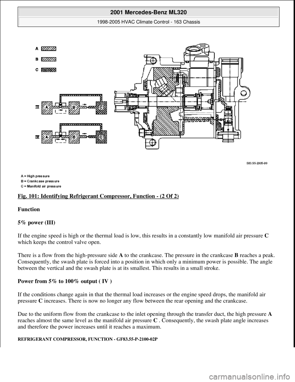
Fig. 101: Identifying Refrigerant Compressor, Function - (2 Of 2)
Function
5% power (III)
If the engine speed is high or the thermal load is low, this results in a constantly low manifold air pressure C
which keeps the control valve open.
There is a flow from the high-pressure side A to the crankcase. The pressure in the crankcase B reaches a peak.
Consequently, the swash plate is forced into a position in which only a minimum power is possible. The angle
between the vertical and the swash plate is at its smallest. This results in a small stroke.
Power from 5% to 100% output ( IV )
If the conditions change again in that the thermal load increases or the engine speed drops, the manifold air
pressure C increases. There is now no longer any flow between the rear opening and the crankcase.
Due to the uniform flow from the crankcase to the inlet opening through the transfer duct, the high pressure A
reaches almost the same level as the manifold air pressure C . Consequently, the swash plate angle increases
and therefore the power increases until it reaches a maximum.
REFRIGERANT COMPRESSOR, FUNCTION - GF83.55-P-2100-02P
2001 Mercedes-Benz ML320
1998-2005 HVAC Climate Control - 163 Chassis
me
Saturday, October 02, 2010 3:23:16 PMPage 123 © 2006 Mitchell Repair Information Company, LLC.
Page 3368 of 4133
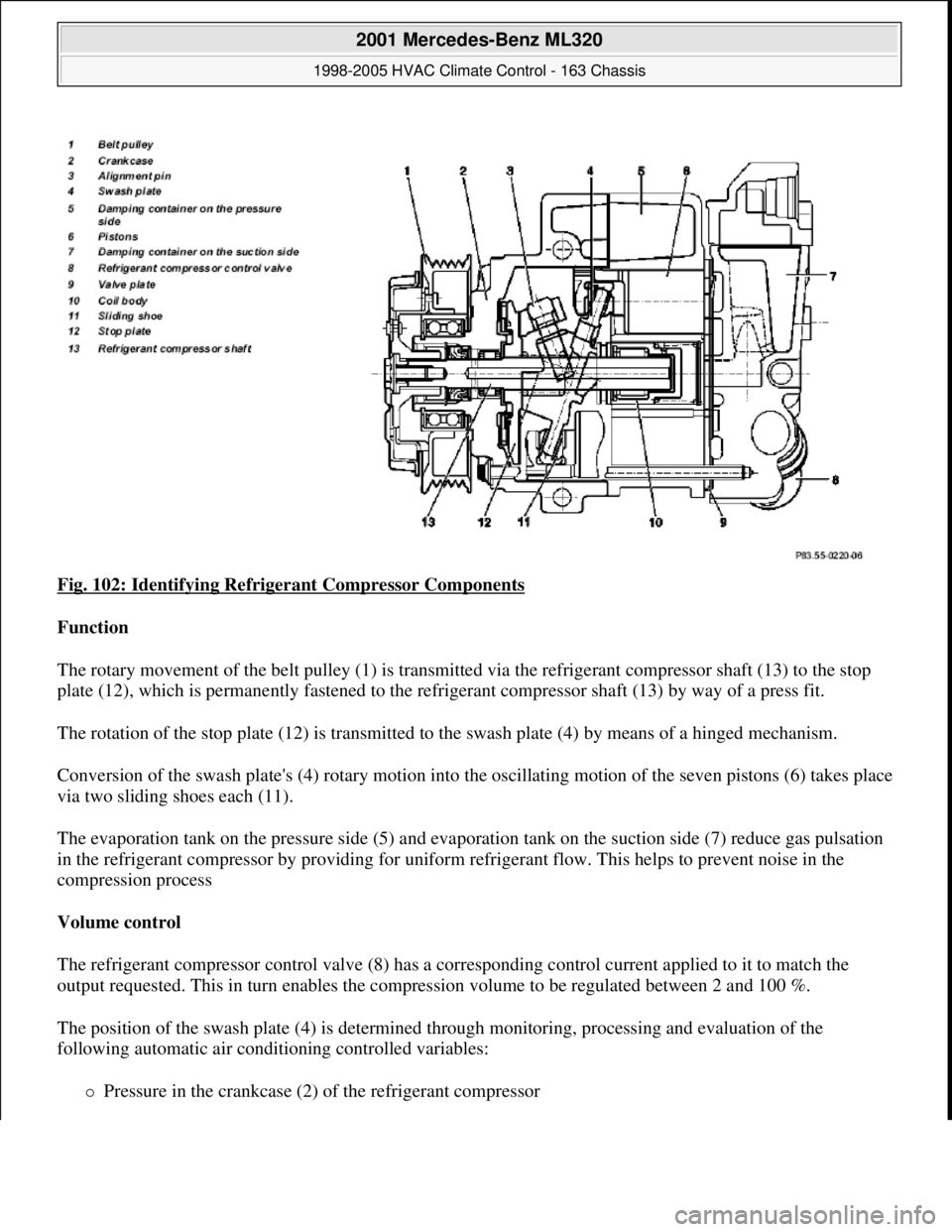
Fig. 102: Identifying Refrigerant Compressor Components
Function
The rotary movement of the belt pulley (1) is transmitted via the refrigerant compressor shaft (13) to the stop
plate (12), which is permanently fastened to the refrigerant compressor shaft (13) by way of a press fit.
The rotation of the stop plate (12) is transmitted to the swash plate (4) by means of a hinged mechanism.
Conversion of the swash plate's (4) rotary motion into the oscillating motion of the seven pistons (6) takes place
via two sliding shoes each (11).
The evaporation tank on the pressure side (5) and evaporation tank on the suction side (7) reduce gas pulsation
in the refrigerant compressor by providing for uniform refrigerant flow. This helps to prevent noise in the
compression process
Volume control
The refrigerant compressor control valve (8) has a corresponding control current applied to it to match the
output requested. This in turn enables the compression volume to be regulated between 2 and 100 %.
The position of the swash plate (4) is determined through monitoring, processing and evaluation of the
following automatic air conditioning controlled variables:
Pressure in the crankcase (2) of the refrigerant compressor
2001 Mercedes-Benz ML320
1998-2005 HVAC Climate Control - 163 Chassis
me
Saturday, October 02, 2010 3:23:16 PMPage 124 © 2006 Mitchell Repair Information Company, LLC.
Page 3369 of 4133
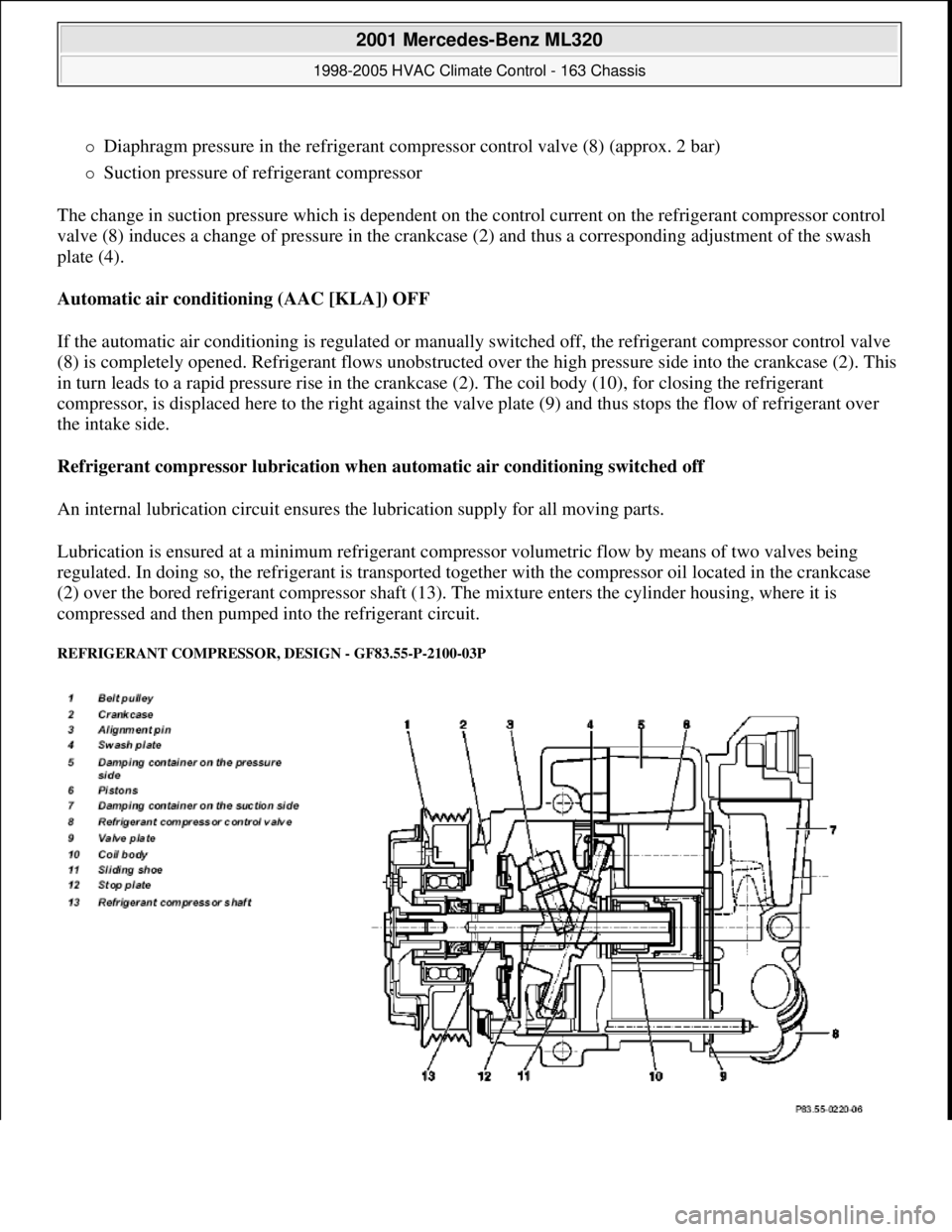
Diaphragm pressure in the refrigerant compressor control valve (8) (approx. 2 bar)
Suction pressure of refrigerant compressor
The change in suction pressure which is dependent on the control current on the refrigerant compressor control
valve (8) induces a change of pressure in the crankcase (2) and thus a corresponding adjustment of the swash
plate (4).
Automatic air conditioning (AAC [KLA]) OFF
If the automatic air conditioning is regulated or manually switched off, the refrigerant compressor control valve
(8) is completely opened. Refrigerant flows unobstructed over the high pressure side into the crankcase (2). This
in turn leads to a rapid pressure rise in the crankcase (2). The coil body (10), for closing the refrigerant
compressor, is displaced here to the right against the valve plate (9) and thus stops the flow of refrigerant over
the intake side.
Refrigerant compressor lubrication when automatic air conditioning switched off
An internal lubrication circuit ensures the lubrication supply for all moving parts.
Lubrication is ensured at a minimum refrigerant compressor volumetric flow by means of two valves being
regulated. In doing so, the refrigerant is transported together with the compressor oil located in the crankcase
(2) over the bored refrigerant compressor shaft (13). The mixture enters the cylinder housing, where it is
compressed and then pumped into the refrigerant circuit.
REFRIGERANT COMPRESSOR, DESIGN - GF83.55-P-2100-03P
2001 Mercedes-Benz ML320
1998-2005 HVAC Climate Control - 163 Chassis
me
Saturday, October 02, 2010 3:23:16 PMPage 125 © 2006 Mitchell Repair Information Company, LLC.
Page 3370 of 4133
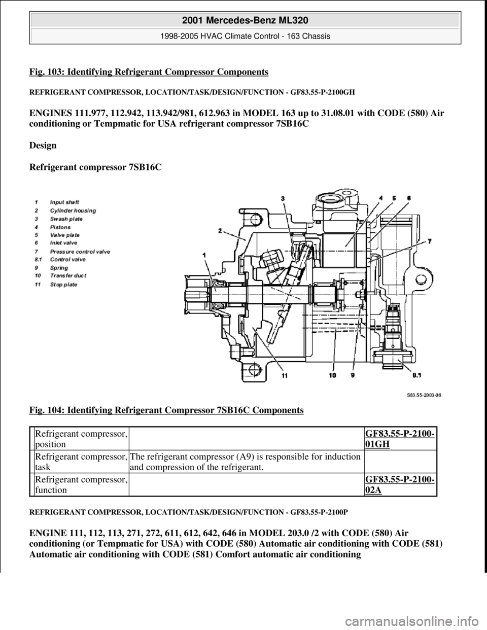
Fig. 103: Identifying Refrigerant Compressor Components
REFRIGERANT COMPRESSOR, LOCATION/TASK/DESIGN/FUNCTION - GF83.55-P-2100GH
ENGINES 111.977, 112.942, 113.942/981, 612.963 in MODEL 163 up to 31.08.01 with CODE (580) Air
conditioning or Tempmatic for USA refrigerant compressor 7SB16C
Design
Refrigerant compressor 7SB16C
Fig. 104: Identifying Refrigerant Compressor 7SB16C Components
REFRIGERANT COMPRESSOR, LOCATION/TASK/DESIGN/FUNCTION - GF83.55-P-2100P
ENGINE 111, 112, 113, 271, 272, 611, 612, 642, 646 in MODEL 203.0 /2 with CODE (580) Air
conditioning (or Tempmatic for USA) with CODE (580) Automatic air conditioning with CODE (581)
Automatic air conditioning with CODE (581) Comfort automatic air conditioning
Refrigerant compressor,
position GF83.55-P-2100-
01GH
Refrigerant compressor,
taskThe refrigerant compressor (A9) is responsible for induction
and compression of the refrigerant.
Refrigerant compressor,
function GF83.55-P-2100-
02A
2001 Mercedes-Benz ML320
1998-2005 HVAC Climate Control - 163 Chassis
me
Saturday, October 02, 2010 3:23:16 PMPage 126 © 2006 Mitchell Repair Information Company, LLC.
Page 3371 of 4133

ENGINE 111, 112, 271, 272, 611, 612, 646 in MODEL 203.7 with CODE (580) Air conditioning (or
Tempmatic for USA) with CODE (580) Automatic air conditioning with CODE (581) Automatic air
conditioning with CODE (581) Comfort automatic air conditioning
ENGINE 112.942 /970, 113.942 /965 /981, 612.963, 628.963 in MODEL 163 as of 1.9.01 with CODE (580)
Automatic air conditioning
ENGINE 112, 113, 271, 272, 273, 612, 642, 646 in MODEL 209.3
ENGINE 112, 113, 271, 272, 273, 642 in MODEL 209.4
Shown on model 203
Fig. 105: Identifying Refrigerant Compressor
- Shown On Model 203
ELECTROMAGNETIC CLUTCH, FUNCTION - GF83.55-P-2101-01A
Electromagnetic clutch (A9k1)
Refrigerant compressor,
positionThe refrigerant compressor (A9) is flange-mounted to the
left front of the engine.
Model 163GF83.55-P-2100-
01GH
Refrigerant compressor,
taskThe refrigerant compressor (A9) is responsible for induction
and compression of the refrigerant.
Refrigerant compressor,
design GF83.55-P-2100-
03P
Refrigerant compressor,
function GF83.55-P-2100-
02P
2001 Mercedes-Benz ML320
1998-2005 HVAC Climate Control - 163 Chassis
me
Saturday, October 02, 2010 3:23:16 PMPage 127 © 2006 Mitchell Repair Information Company, LLC.
Page 3374 of 4133
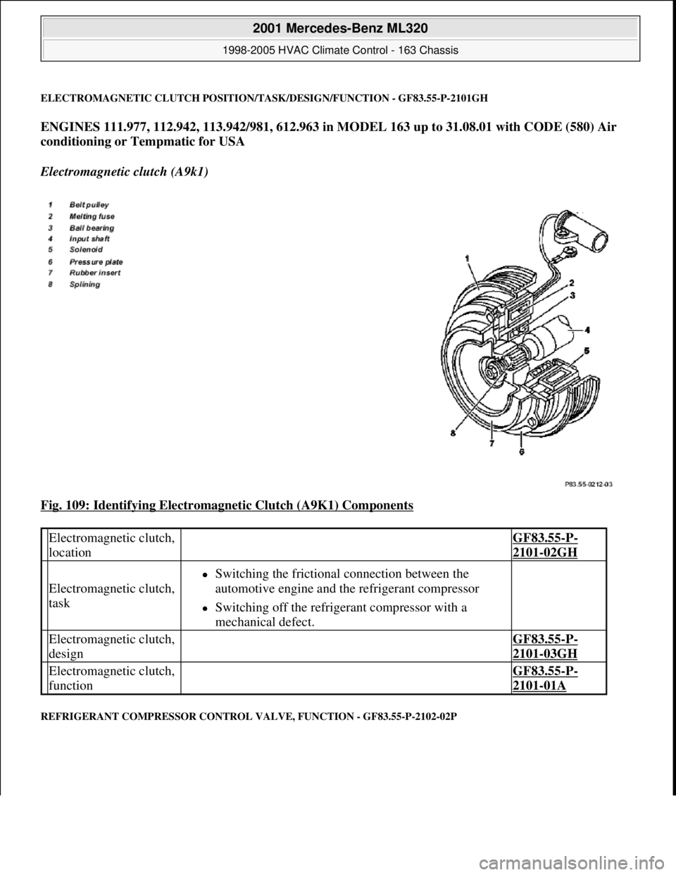
ELECTROMAGNETIC CLUTCH POSITION/TASK/DESIGN/FUNCTION - GF83.55-P-2101GH
ENGINES 111.977, 112.942, 113.942/981, 612.963 in MODEL 163 up to 31.08.01 with CODE (580) Air
conditioning or Tempmatic for USA
Electromagnetic clutch (A9k1)
Fig. 109: Identifying Electromagnetic Clutch (A9K1) Components
REFRIGERANT COMPRESSOR CONTROL VALVE, FUNCTION - GF83.55-P-2102-02P
Electromagnetic clutch,
location GF83.55-P-
2101-02GH
Electromagnetic clutch,
task
Switching the frictional connection between the
automotive engine and the refrigerant compressor
Switching off the refrigerant compressor with a
mechanical defect.
Electromagnetic clutch,
design GF83.55-P-
2101-03GH
Electromagnetic clutch,
function GF83.55-P-
2101-01A
2001 Mercedes-Benz ML320
1998-2005 HVAC Climate Control - 163 Chassis
me
Saturday, October 02, 2010 3:23:16 PMPage 130 © 2006 Mitchell Repair Information Company, LLC.
Page 3376 of 4133
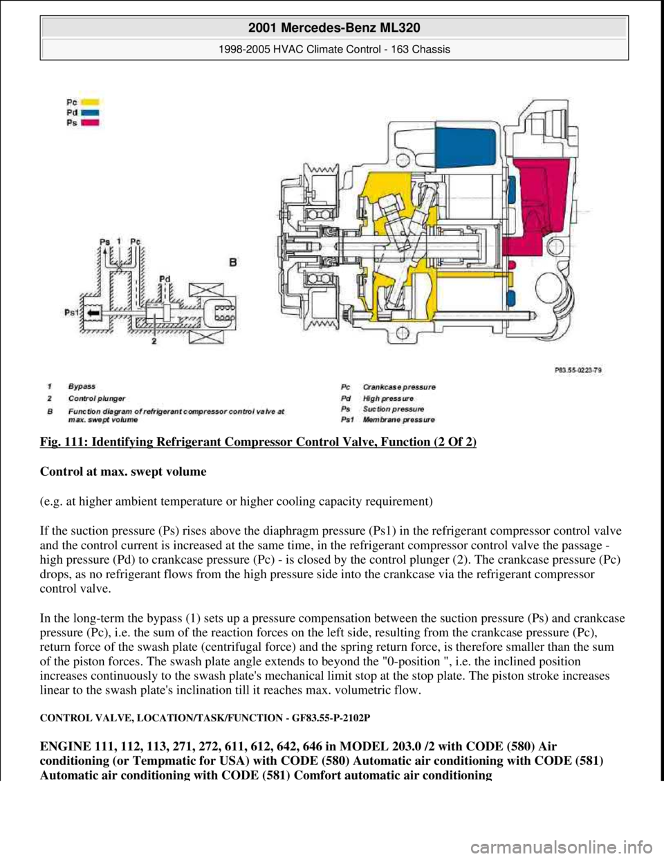
Fig. 111: Identifying Refrigerant Compressor Control Valve, Function (2 Of 2)
Control at max. swept volume
(e.g. at higher ambient temperature or higher cooling capacity requirement)
If the suction pressure (Ps) rises above the diaphragm pressure (Ps1) in the refrigerant compressor control valve
and the control current is increased at the same time, in the refrigerant compressor control valve the passage -
high pressure (Pd) to crankcase pressure (Pc) - is closed by the control plunger (2). The crankcase pressure (Pc)
drops, as no refrigerant flows from the high pressure side into the crankcase via the refrigerant compressor
control valve.
In the long-term the bypass (1) sets up a pressure compensation between the suction pressure (Ps) and crankcase
pressure (Pc), i.e. the sum of the reaction forces on the left side, resulting from the crankcase pressure (Pc),
return force of the swash plate (centrifugal force) and the spring return force, is therefore smaller than the sum
of the piston forces. The swash plate angle extends to beyond the "0-position ", i.e. the inclined position
increases continuously to the swash plate's mechanical limit stop at the stop plate. The piston stroke increases
linear to the swash plate's inclination till it reaches max. volumetric flow.
CONTROL VALVE, LOCATION/TASK/FUNCTION - GF83.55-P-2102P
ENGINE 111, 112, 113, 271, 272, 611, 612, 642, 646 in MODEL 203.0 /2 with CODE (580) Air
conditioning (or Tempmatic for USA) with CODE (580) Automatic air conditioning with CODE (581)
Automatic air conditioning with CODE (581) Comfort automatic air conditioning
2001 Mercedes-Benz ML320
1998-2005 HVAC Climate Control - 163 Chassis
me
Saturday, October 02, 2010 3:23:17 PMPage 132 © 2006 Mitchell Repair Information Company, LLC.