air condition MERCEDES-BENZ ML320 1997 Complete Repair Manual
[x] Cancel search | Manufacturer: MERCEDES-BENZ, Model Year: 1997, Model line: ML320, Model: MERCEDES-BENZ ML320 1997Pages: 4133, PDF Size: 88.89 MB
Page 3338 of 4133
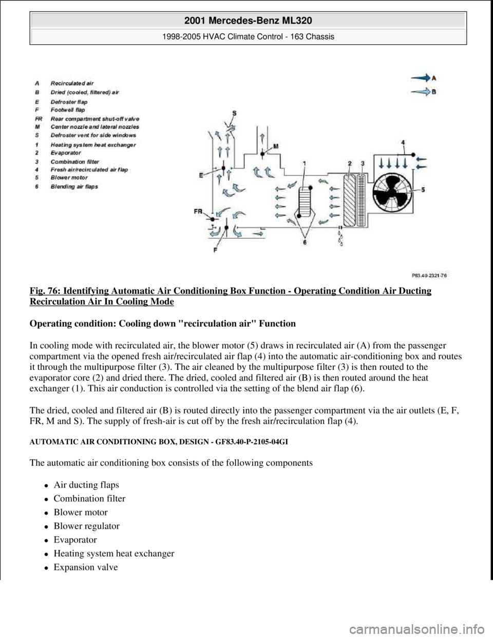
Fig. 76: Identifying Automatic Air Conditioning Box Function - Operating Condition Air Ducting
Recirculation Air In Cooling Mode
Operating condition: Cooling down "recirculation air" Function
In cooling mode with recirculated air, the blower motor (5) draws in recirculated air (A) from the passenger
compartment via the opened fresh air/recirculated air flap (4) into the automatic air-conditioning box and routes
it through the multipurpose filter (3). The air cleaned by the multipurpose filter (3) is then routed to the
evaporator core (2) and dried there. The dried, cooled and filtered air (B) is then routed around the heat
exchanger (1). This air conduction is controlled via the setting of the blend air flap (6).
The dried, cooled and filtered air (B) is routed directly into the passenger compartment via the air outlets (E, F,
FR, M and S). The supply of fresh-air is cut off by the fresh air/recirculation flap (4).
AUTOMATIC AIR CONDITIONING BOX, DESIGN - GF83.40-P-2105-04GI
The automatic air conditioning box consists of the following components
Air ducting flaps
Combination filter
Blower motor
Blower regulator
Evaporator
Heating system heat exchanger
Expansion valve
2001 Mercedes-Benz ML320
1998-2005 HVAC Climate Control - 163 Chassis
me
Saturday, October 02, 2010 3:23:16 PMPage 94 © 2006 Mitchell Repair Information Company, LLC.
Page 3339 of 4133
Blending air flap actuator
Fresh air/recirculated air flap actuator
Defroster vent flap actuator motor
Rear shutoff flap actuator motor
Footwell flap actuator
Electric heater booster (for engine 612.963 only) and therefore forms a complete unit.
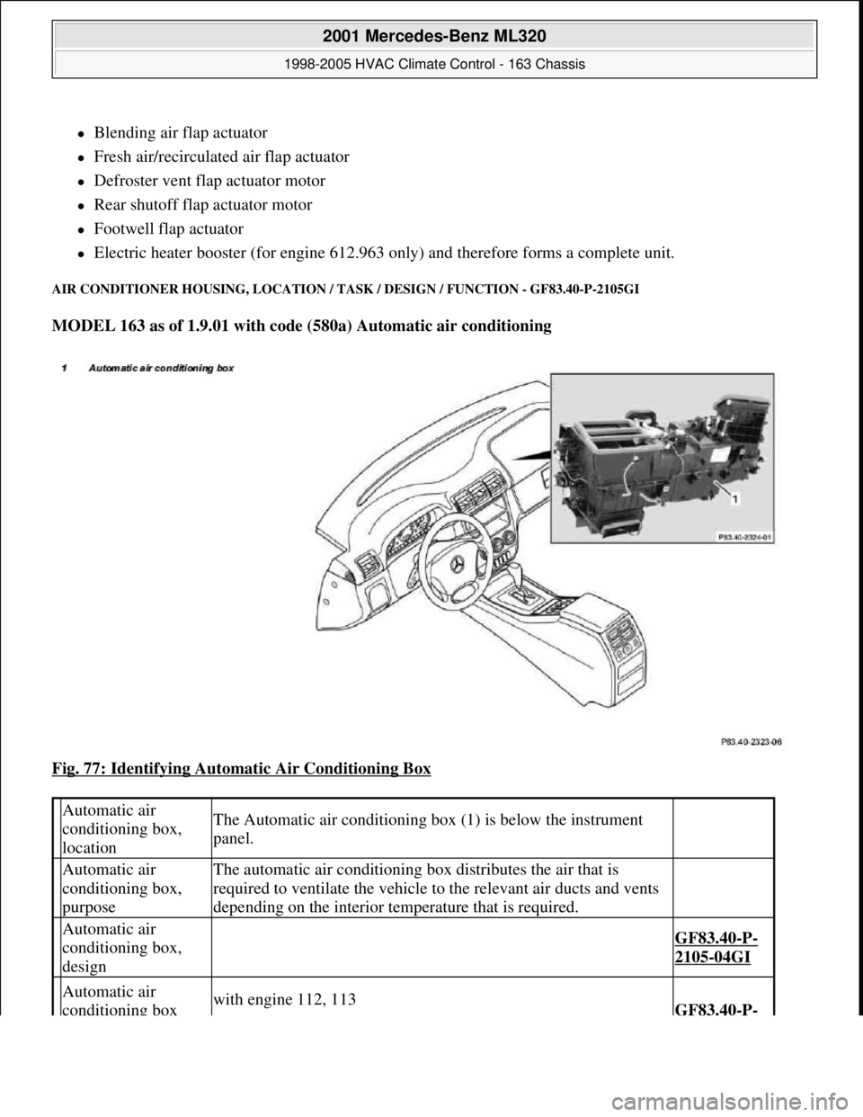
AIR CONDITIONER HOUSING, LOCATION / TASK / DESIGN / FUNCTION - GF83.40-P-2105GI
MODEL 163 as of 1.9.01 with code (580a) Automatic air conditioning
Fig. 77: Identifying Automatic Air Conditioning Box
Automatic air
conditioning box,
locationThe Automatic air conditioning box (1) is below the instrument
panel.
Automatic air
conditioning box,
purposeThe automatic air conditioning box distributes the air that is
required to ventilate the vehicle to the relevant air ducts and vents
depending on the interior temperature that is required.
Automatic air
conditioning box,
design
GF83.40-P-
2105-04GI
Automatic air
conditioning box with engine 112, 113GF83.40-P-
2001 Mercedes-Benz ML320
1998-2005 HVAC Climate Control - 163 Chassis
me
Saturday, October 02, 2010 3:23:16 PMPage 95 © 2006 Mitchell Repair Information Company, LLC.
Page 3340 of 4133
AC OFF BUTTON, FUNCTION - GF83.40-P-2107-01GI
Function
When the AC OFF button ( ) on the automatic air conditioning push-button control module is pressed an
LED comes on, the refrigerant compressor is switched off and cooling therefore switched off The air is no
longer cooled and dried.
Vehicles with diesel engine:
Additionally the electric heater booster is switched off. All other functions are retained.
In order to switch off the refrigerant compressor the push-button control module sends a switch-off request over
the CAN. At the same time, the compressor torque value is set to "0". After a specified time delay the
refrigerant compressor is switched off.
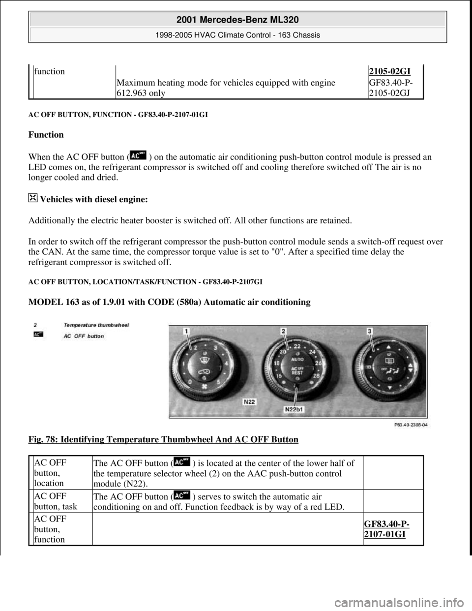
AC OFF BUTTON, LOCATION/TASK/FUNCTION - GF83.40-P-2107GI
MODEL 163 as of 1.9.01 with CODE (580a) Automatic air conditioning
Fig. 78: Identifying Temperature Thumbwheel And AC OFF Button
function2105-02GI
Maximum heating mode for vehicles equipped with engine
612.963 onlyGF83.40-P-
2105-02GJ
AC OFF
button,
locationThe AC OFF button ( ) is located at the center of the lower half of
the temperature selector wheel (2) on the AAC push-button control
module (N22).
AC OFF
button, taskThe AC OFF button ( ) serves to switch the automatic air
conditioning on and off. Function feedback is by way of a red LED.
AC OFF
button,
function
GF83.40-P-
2107-01GI
2001 Mercedes-Benz ML320
1998-2005 HVAC Climate Control - 163 Chassis
me
Saturday, October 02, 2010 3:23:16 PMPage 96 © 2006 Mitchell Repair Information Company, LLC.
Page 3342 of 4133
The all-activity module (AAM) (N10) receives the coolant temperature by the coolant temperature sensor
(B11/4) and the refrigerant pressure by the refrigerant pressure and temperature sensor (B12/2). The all-activity
module (AAM) (N10) compares this input information with stored values and actuates the left auxiliary fan
(M4m1) and the right auxiliary fan (M4m2).
When the following values are indicated the left auxiliary fan (M4m1), right auxiliary fan (M4m2) are switched
on or off:
refrigerant pressure >16 bar = auxiliary fan ON
refrigerant pressure <13 bar = auxiliary fan OFF
coolant temperature > 105°C = auxiliary fan ON
coolant temperature < 97°C = auxiliary fan OFF
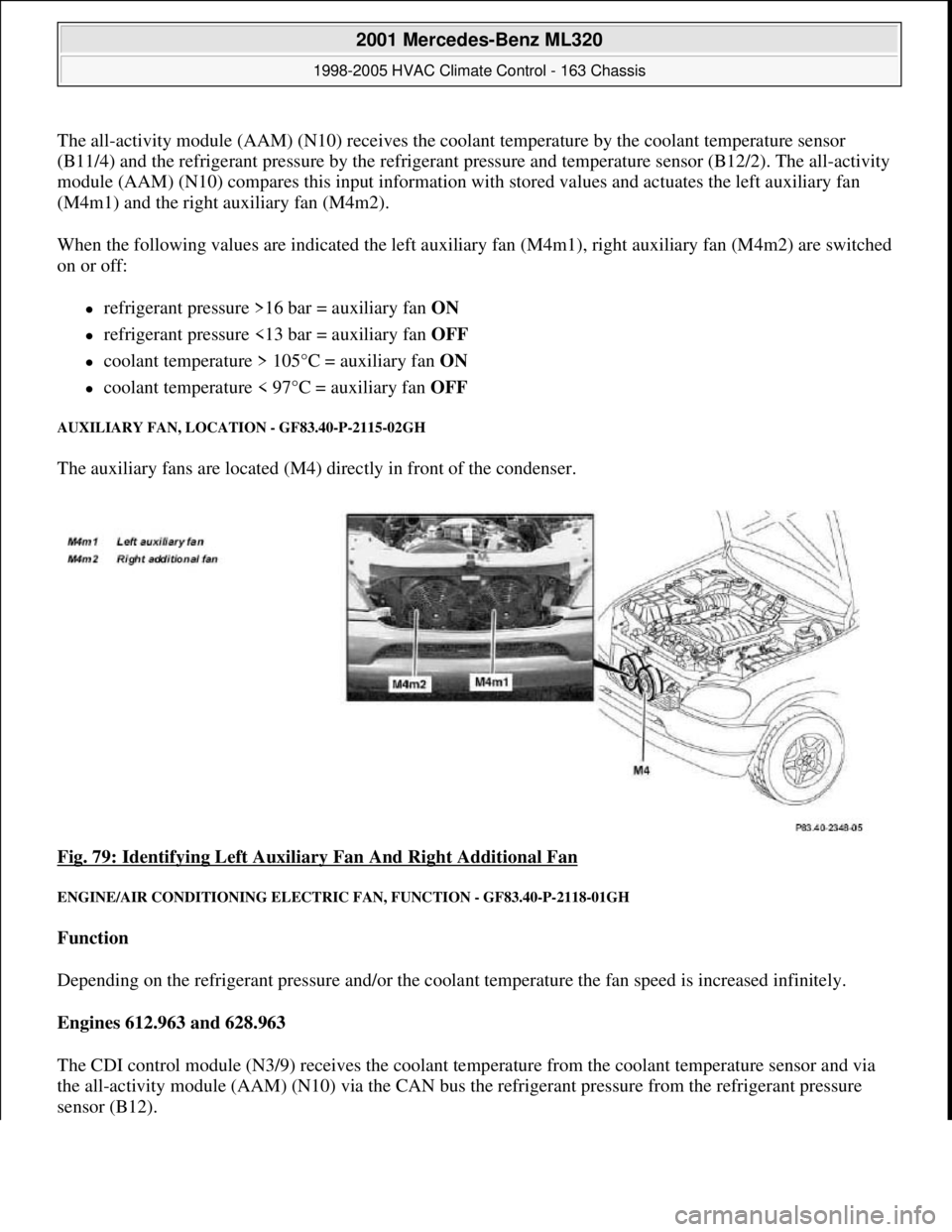
AUXILIARY FAN, LOCATION - GF83.40-P-2115-02GH
The auxiliary fans are located (M4) directly in front of the condenser.
Fig. 79: Identifying Left Auxiliary Fan And Right Additional Fan
ENGINE/AIR CONDITIONING ELECTRIC FAN, FUNCTION - GF83.40-P-2118-01GH
Function
Depending on the refrigerant pressure and/or the coolant temperature the fan speed is increased infinitely.
Engines 612.963 and 628.963
The CDI control module (N3/9) receives the coolant temperature from the coolant temperature sensor and via
the all-activity module (AAM) (N10) via the CAN bus the refrigerant pressure from the refrigerant pressure
sensor (B12).
2001 Mercedes-Benz ML320
1998-2005 HVAC Climate Control - 163 Chassis
me
Saturday, October 02, 2010 3:23:16 PMPage 98 © 2006 Mitchell Repair Information Company, LLC.
Page 3343 of 4133
This input information is relayed by the CDI control module (N3/9) to the integrated control module of the
electric engine/AC intake fan with integrated control (M4/7).
Engines 113.942 and 113.981
The all-activity module (AAM) (N10) receives the coolant temperature via the coolant temperature sensor and
the refrigerant pressure via the refrigerant pressure sensor (B12).
This input information is relayed by the all-activity module (AAM) (N10) to the integrated control module of
the engine and AC electric suction fan with integrated control (M4/7)
There the input information is compared with the stored values and, if necessary, the speed of the engine and
AC electric suction fan with integrated control (M4/7) is increased to 100 %.
The engine and AC electric suction fan with integrated control (M4/7) operates with AC switched on and in the
reheat mode for basic ventilation with a capacity of up to 20 %.
The basic ventilation can be switched off under the following conditions:
At an outdoor temperature of < or = 15°C the value of the outdoor temperature is transmitted from the
outside temperature sensor (B10/5) to the AC control module (N19).
The pressure-dependent fan speed remains the same.
At a vehicle speed of > 75 km/h
The vehicle speed value comes from the traction system control module via the instrument cluster (A1)
and CDI control module (N3/9), to the control module integrated in the electric suction fan engine and
AC with integrated control (M4/7). The pressure-dependent fan speed remains the same.
An overrun time of 60 s can be set in order to ensure that the engine and AC electric suction fan with integrated
control (M4/7) will continue to operate even where the refrigerant compressor is temporarily switched off by
the icing protection.
The engine and AC electric suction fan with integrated control (M4/7) has a power rating of 550W.
ELECTRIC FAN, ENGINE/AIR CONDITIONING, LOCATION - GF83.40-P-2118-02GH
The engine and AC electric suction fan with integrated control (M4/7) is located immediately in front of the
condenser.
2001 Mercedes-Benz ML320
1998-2005 HVAC Climate Control - 163 Chassis
me
Saturday, October 02, 2010 3:23:16 PMPage 99 © 2006 Mitchell Repair Information Company, LLC.
Page 3345 of 4133
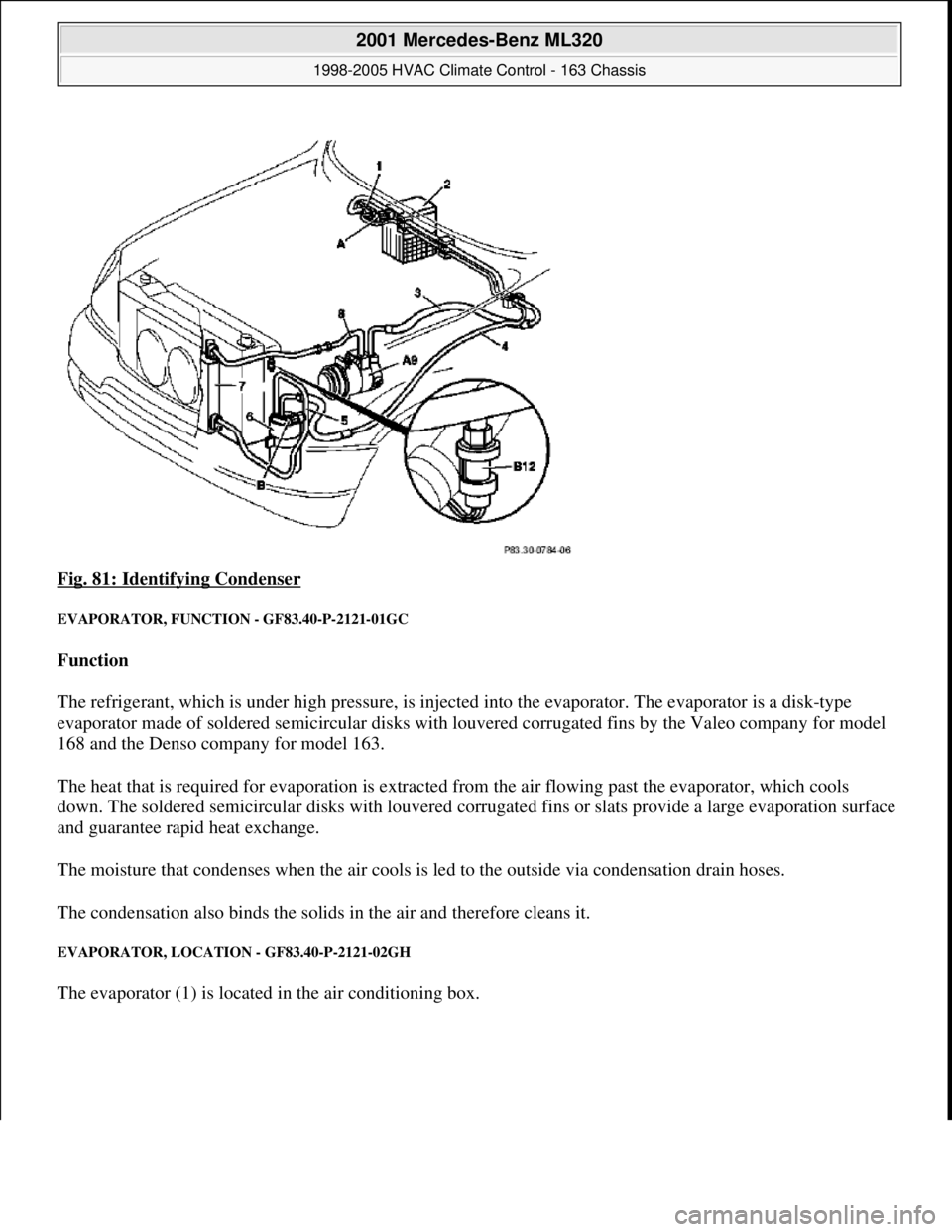
Fig. 81: Identifying Condenser
EVAPORATOR, FUNCTION - GF83.40-P-2121-01GC
Function
The refrigerant, which is under high pressure, is injected into the evaporator. The evaporator is a disk-type
evaporator made of soldered semicircular disks with louvered corrugated fins by the Valeo company for model
168 and the Denso company for model 163.
The heat that is required for evaporation is extracted from the air flowing past the evaporator, which cools
down. The soldered semicircular disks with louvered corrugated fins or slats provide a large evaporation surface
and guarantee rapid heat exchange.
The moisture that condenses when the air cools is led to the outside via condensation drain hoses.
The condensation also binds the solids in the air and therefore cleans it.
EVAPORATOR, LOCATION - GF83.40-P-2121-02GH
The evaporator (1) is located in the air conditioning box.
2001 Mercedes-Benz ML320
1998-2005 HVAC Climate Control - 163 Chassis
me
Saturday, October 02, 2010 3:23:16 PMPage 101 © 2006 Mitchell Repair Information Company, LLC.
Page 3346 of 4133
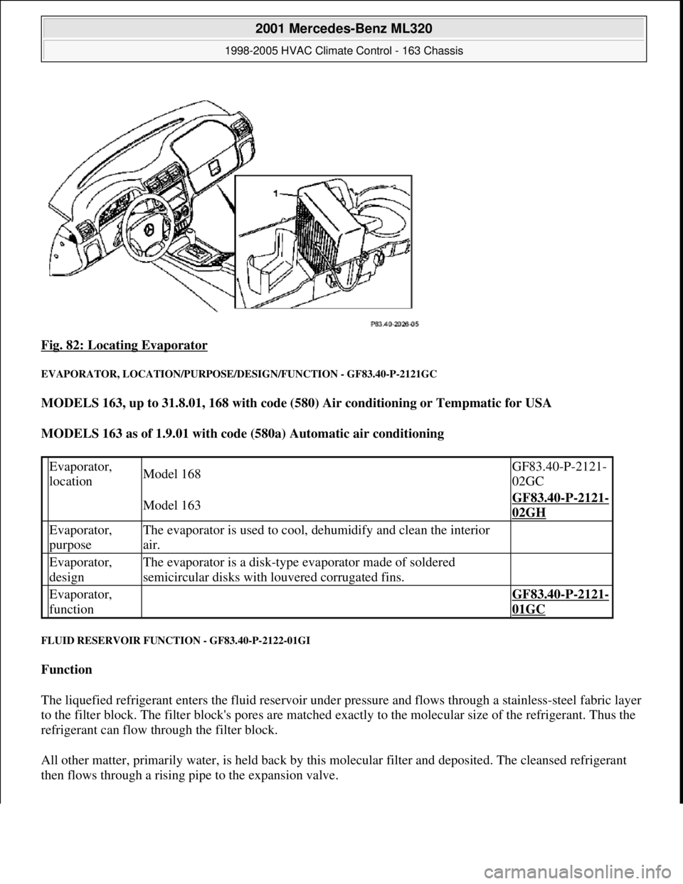
Fig. 82: Locating Evaporator
EVAPORATOR, LOCATION/PURPOSE/DESIGN/FUNCTION - GF83.40-P-2121GC
MODELS 163, up to 31.8.01, 168 with code (580) Air conditioning or Tempmatic for USA
MODELS 163 as of 1.9.01 with code (580a) Automatic air conditioning
FLUID RESERVOIR FUNCTION - GF83.40-P-2122-01GI
Function
The liquefied refrigerant enters the fluid reservoir under pressure and flows through a stainless-steel fabric layer
to the filter block. The filter block's pores are matched exactly to the molecular size of the refrigerant. Thus the
refrigerant can flow through the filter block.
All other matter, primarily water, is held back by this molecular filter and deposited. The cleansed refrigerant
then flows through a rising pipe to the expansion valve.
Evaporator,
locationModel 168GF83.40-P-2121-
02GC
Model 163GF83.40-P-2121-
02GH
Evaporator,
purposeThe evaporator is used to cool, dehumidify and clean the interior
air.
Evaporator,
designThe evaporator is a disk-type evaporator made of soldered
semicircular disks with louvered corrugated fins.
Evaporator,
function GF83.40-P-2121-
01GC
2001 Mercedes-Benz ML320
1998-2005 HVAC Climate Control - 163 Chassis
me
Saturday, October 02, 2010 3:23:16 PMPage 102 © 2006 Mitchell Repair Information Company, LLC.
Page 3348 of 4133
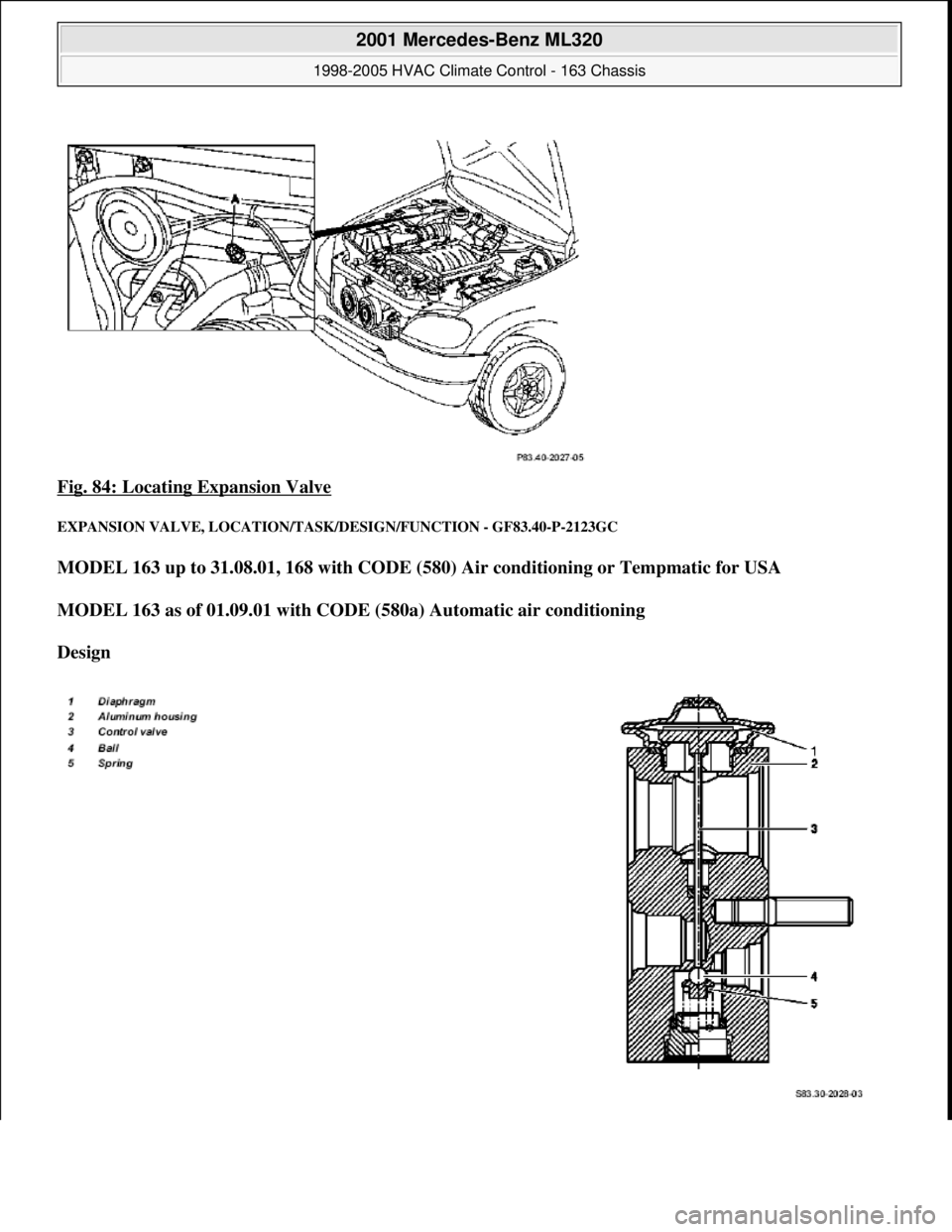
Fig. 84: Locating Expansion Valve
EXPANSION VALVE, LO CATION/TASK/DESIGN/FUNCTION - GF83.40-P-2123GC
MODEL 163 up to 31.08.01, 168 with CODE (580) Ai r conditioning or Tempmatic for USA
MODEL 163 as of 01.09.01 with CODE (580a) Automatic air conditioning
Design
2001 Mercedes-Benz ML320
1998-2005 HVAC Climate Control - 163 Chassis
me
Saturday, October 02, 2010 3:23:16 PMPage 104 © 2006 Mitchell Repair Information Company, LLC.
Page 3351 of 4133
opened.
the injected air is dehumidified, Reheat mode
blend air flaps controlled
footwell nozzles closed
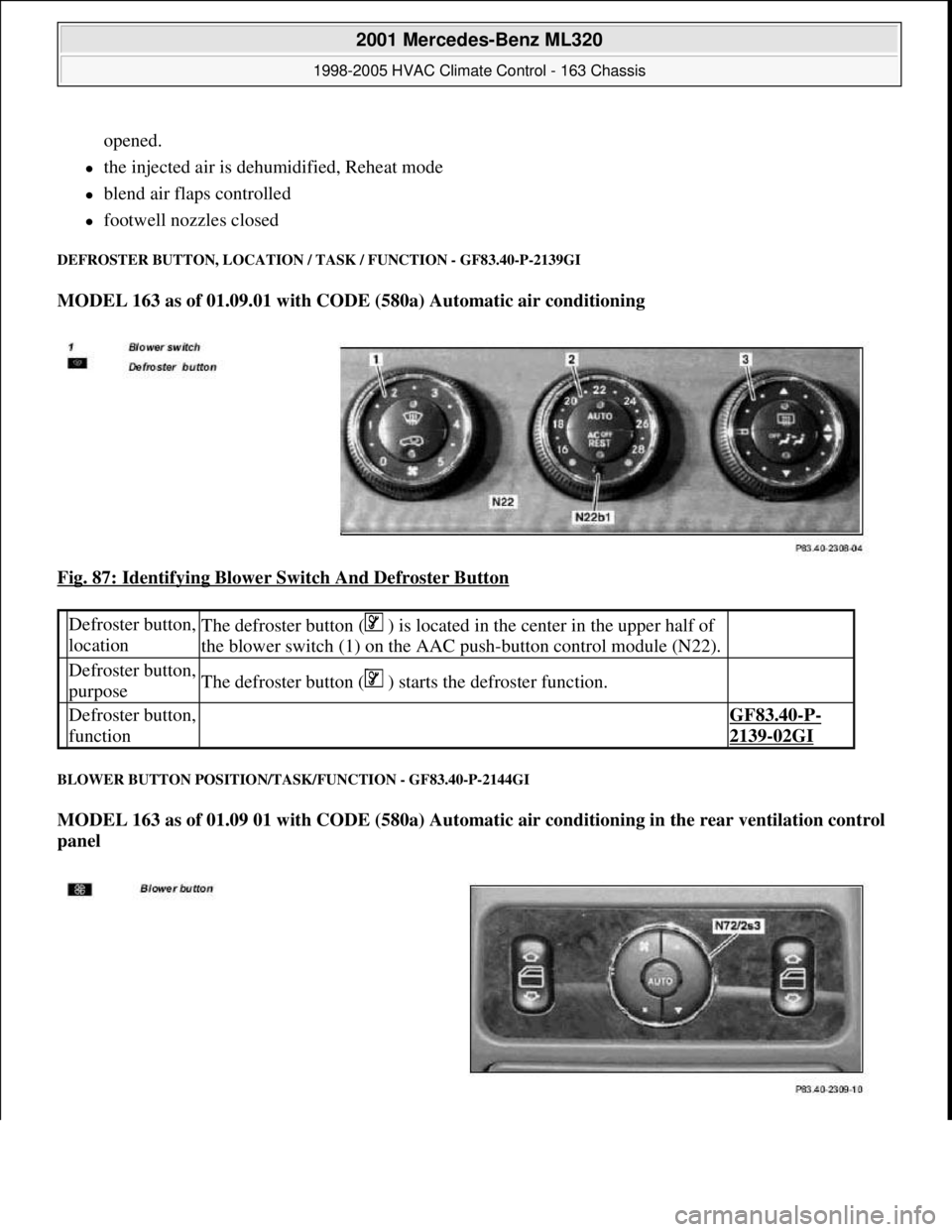
DEFROSTER BUTTON, LOCATION / TASK / FUNCTION - GF83.40-P-2139GI
MODEL 163 as of 01.09.01 with CODE (580a) Automatic air conditioning
Fig. 87: Identifying Blower Switch And Defroster Button
BLOWER BUTTON POSITION/TASK/FUNCTION - GF83.40-P-2144GI
MODEL 163 as of 01.09 01 with CODE (580a) Automatic air conditioning in the rear ventilation control
panel
Defroster button,
locationThe defroster button ( ) is located in the center in the upper half of
the blower switch (1) on the AAC push-button control module (N22).
Defroster button,
purposeThe defroster button ( ) starts the defroster function.
Defroster button,
function GF83.40-P-
2139-02GI
2001 Mercedes-Benz ML320
1998-2005 HVAC Climate Control - 163 Chassis
me
Saturday, October 02, 2010 3:23:16 PMPage 107 © 2006 Mitchell Repair Information Company, LLC.
Page 3352 of 4133
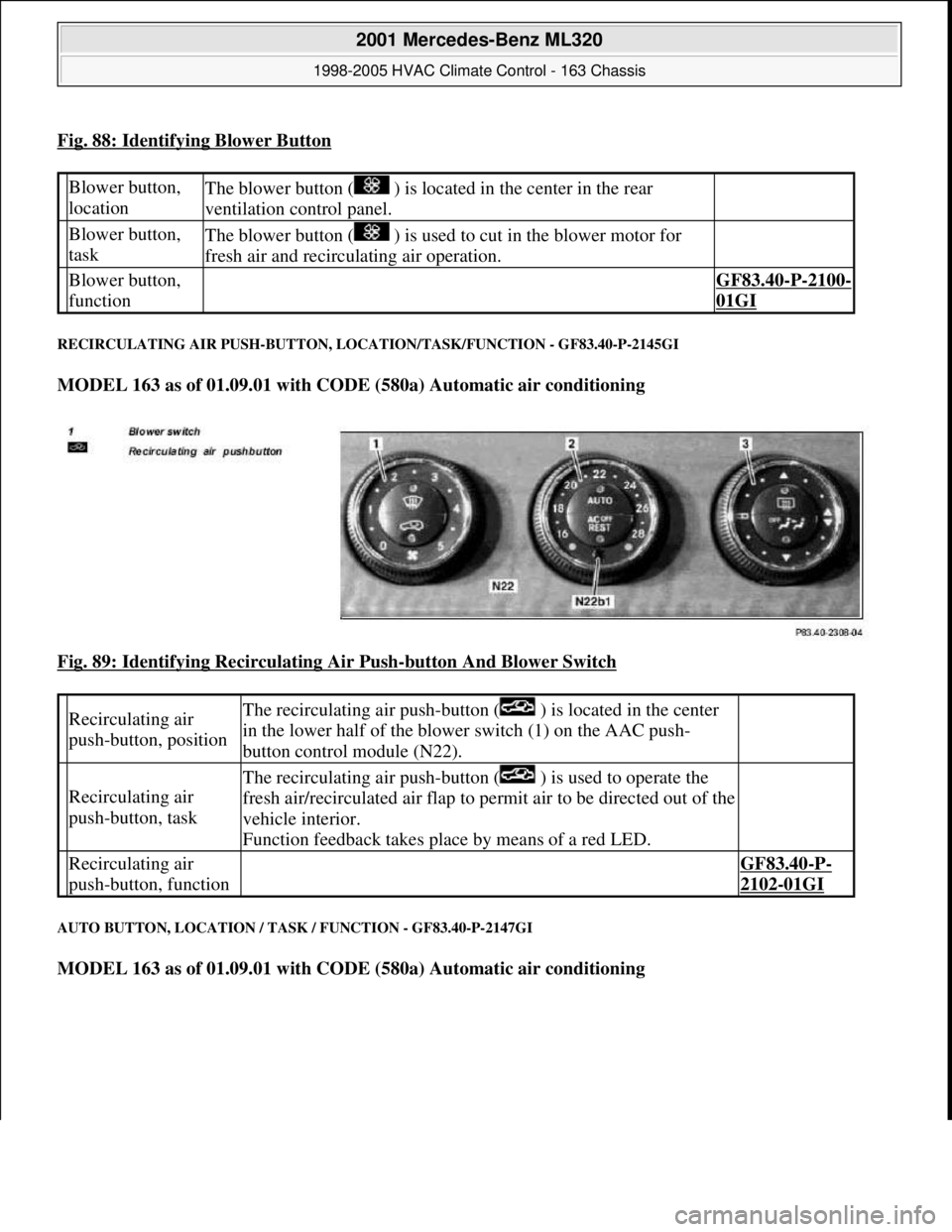
Fig. 88: Identifying Blower Button
RECIRCULATING AIR PUSH-BUTTON, LOCATION/TASK/FUNCTION - GF83.40-P-2145GI
MODEL 163 as of 01.09.01 with CODE (580a) Automatic air conditioning
Fig. 89: Identifying Recirculating Air Push
-button And Blower Switch
AUTO BUTTON, LOCATION / TASK / FUNCTION - GF83.40-P-2147GI
MODEL 163 as of 01.09.01 with CODE (580a) Automatic air conditioning
Blower button,
locationThe blower button ( ) is located in the center in the rear
ventilation control panel.
Blower button,
taskThe blower button ( ) is used to cut in the blower motor for
fresh air and recirculating air operation.
Blower button,
function GF83.40-P-2100-
01GI
Recirculating air
push-button, positionThe recirculating air push-button ( ) is located in the center
in the lower half of the blower switch (1) on the AAC push-
button control module (N22).
Recirculating air
push-button, task
The recirculating air push-button ( ) is used to operate the
fresh air/recirculated air flap to permit air to be directed out of the
vehicle interior.
Function feedback takes place by means of a red LED.
Recirculating air
push-button, function GF83.40-P-
2102-01GI
2001 Mercedes-Benz ML320
1998-2005 HVAC Climate Control - 163 Chassis
me
Saturday, October 02, 2010 3:23:16 PMPage 108 © 2006 Mitchell Repair Information Company, LLC.