air condition MERCEDES-BENZ ML320 1997 Complete Repair Manual
[x] Cancel search | Manufacturer: MERCEDES-BENZ, Model Year: 1997, Model line: ML320, Model: MERCEDES-BENZ ML320 1997Pages: 4133, PDF Size: 88.89 MB
Page 3327 of 4133
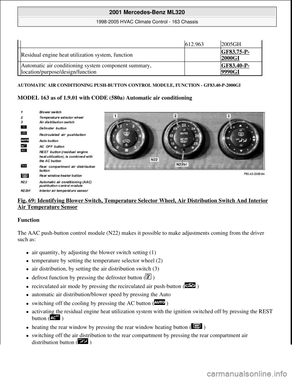
AUTOMATIC AIR CONDITIONING PUSH-BUTTON CONTROL MODULE, FUNCTION - GF83.40-P-2000GI
MODEL 163 as of 1.9.01 with CODE (580a) Automatic air conditioning
Fig. 69: Identifying Blower Switch , Temperature Selector Wheel, Air Di stribution Switch And Interior
Air Temperature Sensor
Function
The AAC push-button control module (N 22) makes it possible to make adjustments coming from the driver
such as:
air quantity, by adjusting the blower switch setting (1)
temperature by setting the temp erature selector wheel (2)
air distribution, by setting the air distribution switch (3)
defrost function by pressing the defroster button ( )
recirculated air mode by pressing th e recirculated air push-button ( )
automatic air distribution/blower speed by pressing the Auto
switching off the cooling by pressing the AC button ( )
activating the residual engine heat ut ilization system with the ignition switched of f by pressing the REST
button ( )
heating the rear window by pressing the rear window heating button ( )
switching off the air distribution to the rear compartment by pressing the rear compartment air
distribution button ( )
612.9632005GH
Residual engine heat util ization system, function GF83.75-P-
2000GI
Automatic air conditioning sy stem component summary,
location/purpose/design/function GF83.40-P-
9990GI
2001 Mercedes-Benz ML320
1998-2005 HVAC Climate Control - 163 Chassis
me
Saturday, October 02, 2010 3:23:16 PMPage 83 © 2006 Mitchell Repair Information Company, LLC.
Page 3328 of 4133
The control module integrated in the AAC push-button control module (N22) looks after all system regulation
and control functions such as:
comparing preselected and actual temperatures and controlling the air temperature at the air outlets
automatic switchover from fresh air to recirculated air mode
electrical control of refrigerant compressor
controlling the auxiliary fan or the electric suction-type fan motor/ air conditioning with integrated
control
The AAC push-button control module (N22) has a diagnostic capability. Consequently, any faults which occur
are stored in the fault memory which can be read with the help of the diagnosis assistant system (DAS).
When the AAC push-button control module is replaced (N22), variant coding must be carried out using the
Diagnosis Assistant System (DAS).
The AAC push-button control module (N22) also performs the following actuations:
direct: refrigerant compressor; heating water circulation pump; PTC heater booster (OM 612 only), rear
window heater
via the CAN BUS: auxiliary fan, electric suction-type fan motor/air conditioning with integrated control,
blower control and air distribution in the rear compartment (automatic mode)
via the AC bus: blower motor; 8 stepping motors for air distribution
The following sensor signals are read in by the AAC push-button control module (N22):
direct: temperature sensor evaporator, pressure and temperature sensor refrigerant, in-car temperature
sensor, center nozzle vent air temperature sensor, footwell and rear passenger compartment, sun sensor
via the CAN BUS: Ambient temperature display temperature sensor, sensor for specified values in rear
control panel
REFRIGERANT CIRCUIT FUNCTION - GF83.40-P-2001GH
MODEL 163 up to 31.8.01 with CODE (580) Air conditioning or Tempmatic for USA
Blower switch, location/task/design/function GF83.25-P-2100GI
Temperature selector wheel, location/task/ design/function GF83.25-P-2102GI
Air distribution switch, location/task/design/ function GF83.25-P-2101GI
Defroster button, location/task/function GF83.40-P-2139GI
Recirculating air push-button, location/task/ function GF83.40-P-2145GI
Auto button, location/task/function GF83.40-P-2147GI
AC OFF button, location/task/function GF83.40-P-2107GI
Rest push-button, location/task/function GF83.40-P-2148GI
Rear passenger compartment air distribution button, location/task/function GF83.40-P-2173GI
2001 Mercedes-Benz ML320
1998-2005 HVAC Climate Control - 163 Chassis
me
Saturday, October 02, 2010 3:23:16 PMPage 84 © 2006 Mitchell Repair Information Company, LLC.
Page 3329 of 4133
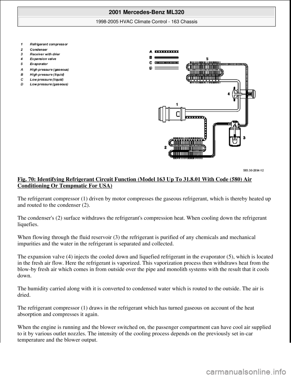
Fig. 70: Identifying Refrigerant Circuit Function (Model 163 Up To 31.8.01 With Code (580) Air
Conditioning Or Tempmatic For USA)
The refrigerant compressor (1) driven by motor compresses the gaseous refrigerant, which is thereby heated up
and routed to the condenser (2).
The condenser's (2) surface withdraws the refrigerant's compression heat. When cooling down the refrigerant
liquefies.
When flowing through the fluid reservoir (3) the refrigerant is purified of any chemicals and mechanical
impurities and the water in the refrigerant is separated and collected.
The expansion valve (4) injects the cooled down and liquefied refrigerant in the evaporator (5), which is located
in the fresh air flow. Here the refrigerant is vaporized. This vaporization process then withdraws heat from the
blow-by fresh air which comes in from outside over the pipe and monolith systems with the result that it cools
down.
The humidity carried along with it is converted to condensed water which is routed to the outside. The air is
dried.
The refrigerant compressor (1) draws in the refrigerant which has turned gaseous on account of the heat
absorption and compresses it again.
When the engine is running and the blower switched on, the passenger compartment can have cool air supplied
to it by various outlet nozzles. The intensity of the cooling process depends on the previously set in-car
temperature and the blower output.
2001 Mercedes-Benz ML320
1998-2005 HVAC Climate Control - 163 Chassis
me
Saturday, October 02, 2010 3:23:16 PMPage 85 © 2006 Mitchell Repair Information Company, LLC.
Page 3330 of 4133
REFRIGERANT CIRCUIT, FUNCTION - GF83.40-P-2001GI
MODEL 163 as of 1.9.01 with code (580a) Automatic air conditioning
Auxiliary fan, location/task/function Engines 111.977, 112.942GF83.40-P-
2162GH
Electric fan motor/air conditioning,
location/task/function Engines 113.942/981 and
612.963GF83.40-P-
2151GH
Condenser position/task/function GF83.40-P-
2152GC
Evaporator, location/purpose/design/function GF83.40-P-
2121GC
Fluid reservoir (TAC), location/task/function GF83.30-P-
2120GC
Expansion valve, location/task/design/function GF83.40-P-
2123GC
Refrigerant pressure sensor, location/task/ function GF83.40-P-
2156GH
Refrigerant compressor, location/task/design/
function GF83.55-P-
2100GH
Air conditioning control module, location/task/
function GF83.30-P-
2102GH
All-activity module, location/task/design/ function GF54.21-P-
4110GH
Extended-activity module, position/task GF54.21-P-
4106GH
Extended-activity module, location/task/designas of 1.12.99GF54.21-P-
4107GK
CDI control module, location/task/function Engine 612.963GF07.16-P-
3102IA
2001 Mercedes-Benz ML320
1998-2005 HVAC Climate Control - 163 Chassis
me
Saturday, October 02, 2010 3:23:16 PMPage 86 © 2006 Mitchell Repair Information Company, LLC.
Page 3331 of 4133
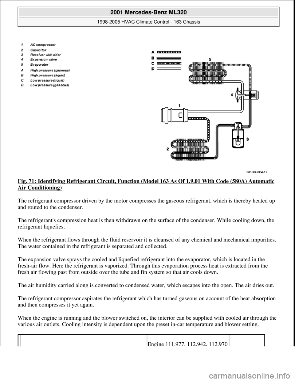
Fig. 71: Identifying Refrigerant Circuit, Function (Model 163 As Of 1.9.01 With Code (580A) Automatic
Air Conditioning)
The refrigerant compressor driven by the motor compresses the gaseous refrigerant, which is thereby heated up
and routed to the condenser.
The refrigerant's compression heat is then withdrawn on the surface of the condenser. While cooling down, the
refrigerant liquefies.
When the refrigerant flows through the fluid reservoir it is cleansed of any chemical and mechanical impurities.
The water contained in the refrigerant is separated and collected.
The expansion valve sprays the cooled and liquefied refrigerant into the evaporator, which is located in the
fresh-air flow. Here the refrigerant is vaporized. Through this evaporation process heat is extracted from the
fresh air flowing past from outside over the tube and fin system so that air cools down.
The air humidity carried along is converted to condensed water, which escapes into the open. The air dries out.
The refrigerant compressor aspirates the refrigerant which has turned gaseous on account of the heat absorption
and then compresses it yet again.
When the engine is running and the blower switched on, the interior can be supplied with cooled air through the
various air outlets. Cooling intensity is dependent upon the preset in-car temperature and blower setting.
Engine 111.977, 112.942, 112.970
2001 Mercedes-Benz ML320
1998-2005 HVAC Climate Control - 163 Chassis
me
Saturday, October 02, 2010 3:23:16 PMPage 87 © 2006 Mitchell Repair Information Company, LLC.
Page 3332 of 4133
REAR VENTILATION CO NTROL PANEL, FUNCTION - GF83.40-P-2007GI
MODEL 163 as of 1.9.01 with CODE (580a) Automatic air conditioning
N72/2s3 Rear ventilation control panel
Auto button
Air distribution button
Blower button
Auxiliary fan, location/purpose/function
with code 580 up to 31.08.01
Engine 112.942, 112.970 with
code 580a as of 01.09.01GF83.40-P-
2162GH
Engine and AC electric su ction fan with integrated
control, location/purpose/function
Engine 113.942 with code 580a up
to 31.08.01
Engine 113.981, 113.965, 612.963,
628.963 with code 580a as of
01.09.01
GF83.40-P-
2172GI
Condenser, location/purpose/function GF83.40-P-
2152GC
Evaporator location/purpose/design/function GF83.40-P-
2121GC
Fluid reservoir, location/purpose/function GF83.40-P-
2153GI
Expansion valve, locati on/purpose/design/ function GF83.40-P-
2123GC
Refrigerant pressure and temperature sensor,
location/purpose/function GF83.40-P-
2171GI
Refrigerant compressor, location/purpose/
design/function GF83.55-P-
2100P
Control valve, location/purpose/function GF83.55-P-
2102P
Belt pulley, location/ purpose/design/function GF83.55-P-
2103P
Pressure relief valve, location/purpose/function GF83.55-P-
2104P
2001 Mercedes-Benz ML320
1998-2005 HVAC Climate Control - 163 Chassis
me
Saturday, October 02, 2010 3:23:16 PMPage 88 © 2006 Mitchell Repair Information Company, LLC.
Page 3334 of 4133
Air distribution button ( ) = air duc ting to rear compartment nozzle
Air distribution button ( ) = air ducting to the air outlets in the rear footwell
The automatic air distribution function can be set by pr essing the Auto button, whereby control is assumed by
the AAC push-button c ontrol module (N22).
RECIRCULATING AIR PU SH-BUTTON, FUNCTION - GF83.40-P-2102-01GI
Function
A brief actuation (< 1.5 s) of the recirculating air pus h-button ( ) energizes the actuator motor for the fresh
air/recirculated air flap, whic h activates the fresh air/recirculated air fl ap and thus closes the fresh air duct and
opens the recirculation duct, in or der to enable the air supply from the passenger compartment. The function
LED illuminates during recirculation mode.
Recirculated air convenience closing function
If the recirculating air pus h-button ( ) is pressed for longer than > 2 s, then alongside the recirculation
function, all open windows and the sliding and tilting roof are automatically closed (window and sliding/
tilting roof must ha ve been normalized ). The function LED illuminates durin g recirculation mode. In order to
prevent any current peaks the sliding/tilting sunroof and power windows are actuated successively.
If the push-button is pressed again for > 2 s, the windows a nd the sliding/tilting sunroof return to the previously
stored position and the fresh air/ recirculated air flap moves to the fresh air position (LED off).
The convenience closing function can only be started if the recirculating LED is not illuminated.
Each window, which has been manually opened during the r ecirculation phase, remains in this position if the
recirculating function is cleared: all other windows move to the stor ed positions. The position of the
sliding/tilting sunroof prior to the st art of the closing operation and that of the side windows is stored in the
memory. The windows and the sliding/tilting sunroof wh ich have been closed by the convenience closing
function, remain closed if the recirculation push-
button was only pressed briefly (t < 1.5 s). In this case, only the
fresh air/recirculated air flap is moved to the fresh-air position. The stored positions are cleared when the
ignition is switched off.
AUTOMATIC AIR CONDITIONING BOX FUNCTION - GF83.40-P-2105-02GI
Operating condition: Air ducting under heater operation
2001 Mercedes-Benz ML320
1998-2005 HVAC Climate Control - 163 Chassis
me
Saturday, October 02, 2010 3:23:16 PMPage 90 © 2006 Mitchell Repair Information Company, LLC.
Page 3335 of 4133
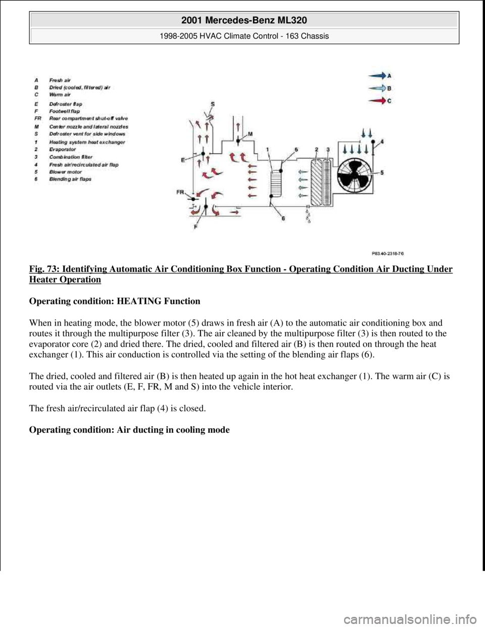
Fig. 73: Identifying Automatic Air Conditioning Box Function - Operating Condition Air Ducting Under
Heater Operation
Operating condition: HEATING Function
When in heating mode, the blower motor (5) draws in fresh air (A) to the automatic air conditioning box and
routes it through the multipurpose filter (3). The air cleaned by the multipurpose filter (3) is then routed to the
evaporator core (2) and dried there. The dried, cooled and filtered air (B) is then routed on through the heat
exchanger (1). This air conduction is controlled via the setting of the blending air flaps (6).
The dried, cooled and filtered air (B) is then heated up again in the hot heat exchanger (1). The warm air (C) is
routed via the air outlets (E, F, FR, M and S) into the vehicle interior.
The fresh air/recirculated air flap (4) is closed.
Operating condition: Air ducting in cooling mode
2001 Mercedes-Benz ML320
1998-2005 HVAC Climate Control - 163 Chassis
me
Saturday, October 02, 2010 3:23:16 PMPage 91 © 2006 Mitchell Repair Information Company, LLC.
Page 3336 of 4133
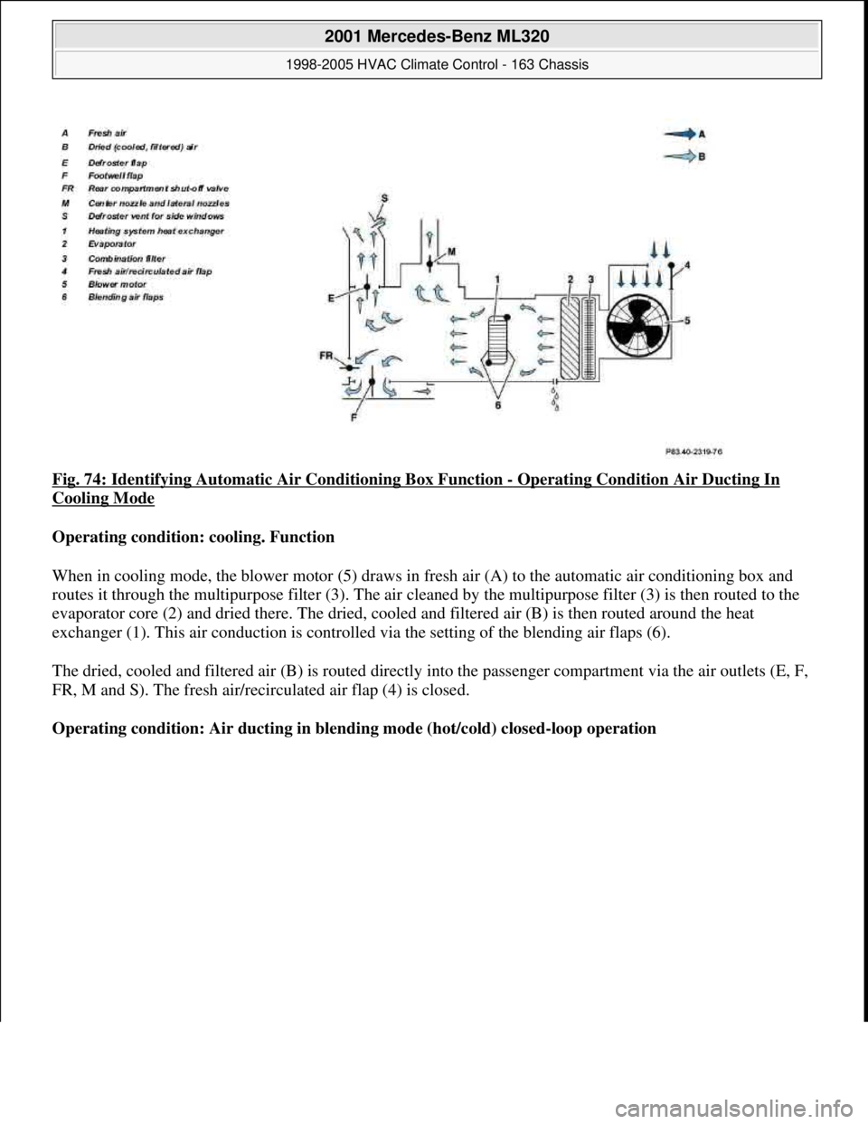
Fig. 74: Identifying Automatic Air Conditioning Box Function - Operating Condition Air Ducting In
Cooling Mode
Operating condition: cooling. Function
When in cooling mode, the blower motor (5) draws in fresh air (A) to the automatic air conditioning box and
routes it through the multipurpose filter (3). The air cleaned by the multipurpose filter (3) is then routed to the
evaporator core (2) and dried there. The dried, cooled and filtered air (B) is then routed around the heat
exchanger (1). This air conduction is controlled via the setting of the blending air flaps (6).
The dried, cooled and filtered air (B) is routed directly into the passenger compartment via the air outlets (E, F,
FR, M and S). The fresh air/recirculated air flap (4) is closed.
Operating condition: Air ducting in blending mode (hot/cold) closed-loop operation
2001 Mercedes-Benz ML320
1998-2005 HVAC Climate Control - 163 Chassis
me
Saturday, October 02, 2010 3:23:16 PMPage 92 © 2006 Mitchell Repair Information Company, LLC.
Page 3337 of 4133
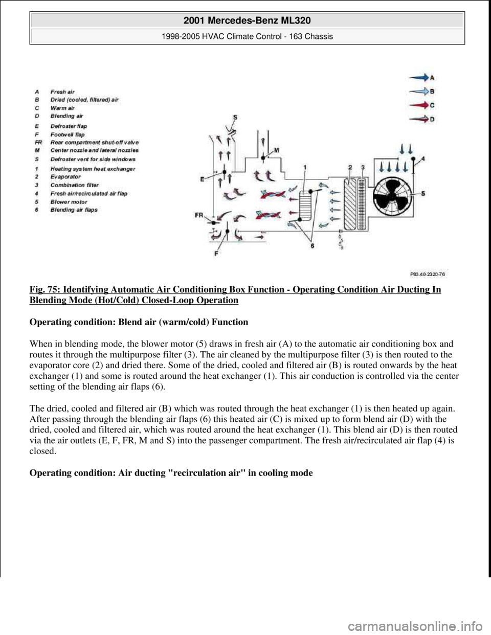
Fig. 75: Identifying Automatic Air Conditioning Box Function - Operating Condition Air Ducting In
Blending Mode (Hot/Cold) Closed-Loop Operation
Operating condition: Blend air (warm/cold) Function
When in blending mode, the blower motor (5) draws in fresh air (A) to the automatic air conditioning box and
routes it through the multipurpose filter (3). The air cleaned by the multipurpose filter (3) is then routed to the
evaporator core (2) and dried there. Some of the dried, cooled and filtered air (B) is routed onwards by the heat
exchanger (1) and some is routed around the heat exchanger (1). This air conduction is controlled via the center
setting of the blending air flaps (6).
The dried, cooled and filtered air (B) which was routed through the heat exchanger (1) is then heated up again.
After passing through the blending air flaps (6) this heated air (C) is mixed up to form blend air (D) with the
dried, cooled and filtered air, which was routed around the heat exchanger (1). This blend air (D) is then routed
via the air outlets (E, F, FR, M and S) into the passenger compartment. The fresh air/recirculated air flap (4) is
closed.
Operating condition: Air ducting "recirculation air" in cooling mode
2001 Mercedes-Benz ML320
1998-2005 HVAC Climate Control - 163 Chassis
me
Saturday, October 02, 2010 3:23:16 PMPage 93 © 2006 Mitchell Repair Information Company, LLC.