MERCEDES-BENZ ML430 1997 Complete Repair Manual
Manufacturer: MERCEDES-BENZ, Model Year: 1997, Model line: ML430, Model: MERCEDES-BENZ ML430 1997Pages: 4133, PDF Size: 88.89 MB
Page 3561 of 4133

1Remove front seats 1000GH
2.1Remove bass module speaker Only with Sound-System, Code 810.AR82.62-P-
7839GH
3.1Remove control module for
emergency call system Only with emergency call system E-Call,
Code 349.AR82.95-P-
0008GH
4Remove bench 1/3 bench seat, up to 31.8.99.AR91.12-P-
1010GH
40% bench seat, as of 01.9.99.AR91.12-P-
1010GI
2/3 bench seat, up to 31.8.99.AR91.12-P-
1010GJ
60% bench seat, as of 01.9.99.AR91.12-P-
1010GK
5Remove rear seat anchors (2) Up to 31.8.99, unscrew internal Torx drive
bolts (3).
Torx bit setFig. 24
6Remove center console (4) AR68.20-P-
2000GH
7Remove cover below instrument
panel on left (6) AR68.10-P-
1500GH
8Remove cover below instrument
panel on right (5) Up to 31.8.99.AR68.10-P-
1520GH
As of 01.9.99.AR68.10-P-
1520GI
9Unscrew plastic nuts (11) in right
footwell
10Remove condensate water drain
hose from heater housing
11
Remove door sill molding on
right (9) and door sill molding on
left (10)
AR68.30-P-
4100GH
12
Remove paneling in footwell on
right (7) and paneling in footwell
on left (8)
AR68.30-P-
4010GH
13Remove insulating mat under the
center console
14Remove air duct for ventilation in
the rear
15Remove radio AR82.60-P-
7502EA
16Disconnect all the electrical
connectors and lay aside
17Detach shift-lock cable at the
electronic selector module
2001 Mercedes-Benz ML320
1998-2005 ACCESSORIES & BODY, CAB Interior Equipment - 163 Chassis
me
Saturday, October 02, 2010 3:35:22 PMPage 43 © 2006 Mitchell Repair Information Company, LLC.
Page 3562 of 4133

Instrument panel
Fig. 40: Identifying Torx Bit Set (000 589 01 10 00)
DISASSEMBLING AND ASSEMBLING CENTER CONSOLE - AR68.20-P-2150GH
MODEL 163.113 /136 /154 /172 /174 up to 31.8.01
18
Remove bracket between
instrument panel center part and
transmission tunnel
*BA68.10-P-
1003-01A
19Pull out floor covering (1) in area
of C-pillar and remove
Do not damage electrical leads.
Installation: Align floor covering at
attachment points for seats and thread electric
wires through corresponding cutouts.
20Install in the reverse order
NumberDesignationMODEL Series 163
BA68.10-P-1003-01AScrew, dashboard to transmission tunnelNm30
2001 Mercedes-Benz ML320
1998-2005 ACCESSORIES & BODY, CAB Interior Equipment - 163 Chassis
me
Saturday, October 02, 2010 3:35:22 PMPage 44 © 2006 Mitchell Repair Information Company, LLC.
Page 3563 of 4133

Fig. 41: Identifying Center Console Components Up To 31.8.01
DISASSEMBLE/ASSEMBLE CENTER CONSOLE - AR68.20-P-2150GI
Disassemble/assemble
1Remove center console AR68.20-P-
2000GH
2Lay center console (1) down on suitable
subsurface with opening pointing downward
3Remove rear power window switches
(S21/15s1) and (S21/15s2) Remove switch to inside
and cover (2) to outside
4Remove rear ashtray housing (3)
5Unclip cup holder (4) from cover (5)
6Remove cover (5) for cup holder
7Remove inner section (6) Installation:Install inner
section at top.
8Separate center console on top section (7) and
bottom section (8) 6 screws
9Assemble in reverse sequence
2001 Mercedes-Benz ML320
1998-2005 ACCESSORIES & BODY, CAB Interior Equipment - 163 Chassis
me
Saturday, October 02, 2010 3:35:22 PMPage 45 © 2006 Mitchell Repair Information Company, LLC.
Page 3564 of 4133

MODEL 163.113 /154 /174 #A as of 289565,163.113 #X as of 754620,163.128 /157 /175
Fig. 42: Identifying Center Console Components
Disassemble/assemble
1Remove center console AR68.20-
P-2000GH
2Lay center console down on
suitable subsurface
3Remove front ashtray (1) AR68.20-
P-2400GI
4Remove storage compartment
(2)
5Remove rear center console
(3) AR68.20-
P-2020GI
6Remove rear air nozzle (4) AR83.10-
P-4800GH
7Remove RCP console module
(N72/2) AR68.20-
P-2210GH
8.1Remove rear beverage holder
(5)
Model 163.154 #A as of VIN 145273 up to VIN
289564, model 163.172 #A as of VIN 145273,
model 163.113 /174 #A up to VIN 289564, model
163.136 /154 /172 #X as of VIN 708319, model
163.113 #X up to VIN 754619
AR68.20-
P-2220GH
2001 Mercedes-Benz ML320
1998-2005 ACCESSORIES & BODY, CAB Interior Equipment - 163 Chassis
me
Saturday, October 02, 2010 3:35:22 PMPage 46 © 2006 Mitchell Repair Information Company, LLC.
Page 3565 of 4133

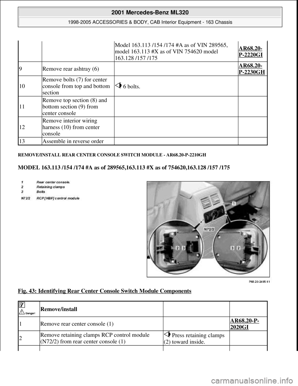
REMOVE/INSTALL REAR CENTER CONSOLE SWITCH MODULE - AR68.20-P-2210GH
MODEL 163.113 /154 /174 #A as of 289565,163.113 #X as of 754620,163.128 /157 /175
Fig. 43: Identifying Rear Center Console Switch Module Components
Model 163.113 /154 /174 #A as of VIN 289565,
model 163.113 #X as of VIN 754620 model
163.128 /157 /175AR68.20-
P-2220GI
9Remove rear ashtray (6) AR68.20-
P-2230GH
10
Remove bolts (7) for center
console from top and bottom
section
6 bolts.
11
Remove top section (8) and
bottom section (9) from
center console
12
Remove interior wiring
harness (10) from center
console
13Assemble in reverse order
Remove/install
1Remove rear center console (1) AR68.20-P-
2020GI
2Remove retaining clamps RCP control module
(N72/2) from rear center console (1) Press retaining clamps
(2) toward inside.
2001 Mercedes-Benz ML320
1998-2005 ACCESSORIES & BODY, CAB Interior Equipment - 163 Chassis
me
Saturday, October 02, 2010 3:35:22 PMPage 47 © 2006 Mitchell Repair Information Company, LLC.
Page 3566 of 4133

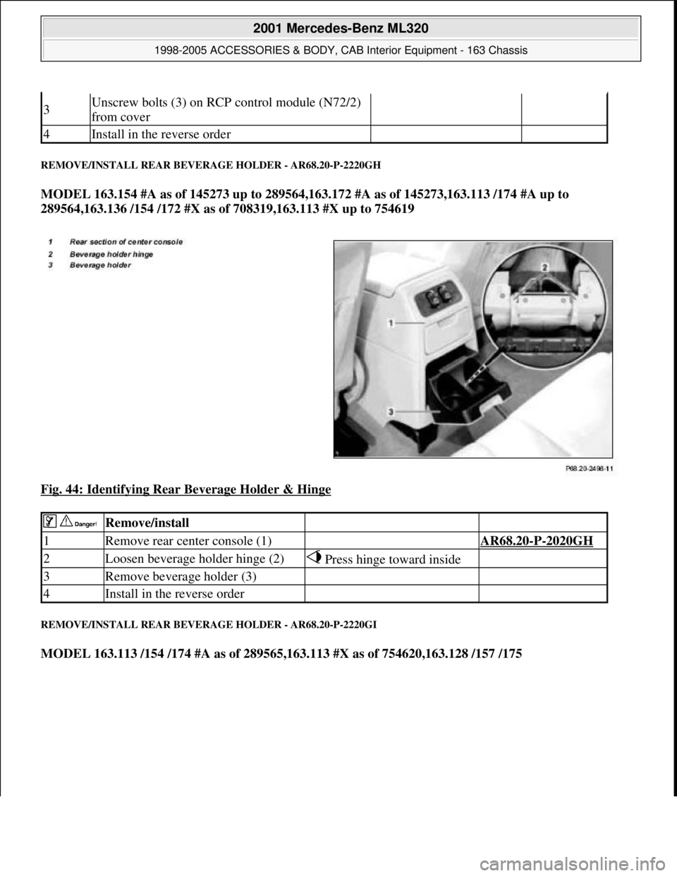
REMOVE/INSTALL REAR BEVERAGE HOLDER - AR68.20-P-2220GH
MODEL 163.154 #A as of 145273 up to 289564,163.172 #A as of 145273,163.113 /174 #A up to
289564,163.136 /154 /172 #X as of 708319,163.113 #X up to 754619
Fig. 44: Identifying Rear Beverage Holder & Hinge
REMOVE/INSTALL REAR BEVERAGE HOLDER - AR68.20-P-2220GI
MODEL 163.113 /154 /174 #A as of 289565,163.113 #X as of 754620,163.128 /157 /175
3Unscrew bolts (3) on RCP control module (N72/2)
from cover
4Install in the reverse order
Remove/install
1Remove rear center console (1) AR68.20-P-2020GH
2Loosen beverage holder hinge (2) Press hinge toward inside
3Remove beverage holder (3)
4Install in the reverse order
2001 Mercedes-Benz ML320
1998-2005 ACCESSORIES & BODY, CAB Interior Equipment - 163 Chassis
me
Saturday, October 02, 2010 3:35:22 PMPage 48 © 2006 Mitchell Repair Information Company, LLC.
Page 3567 of 4133

Fig. 45: Identifying Rear Beverage Holder Components
REMOVE/INSTALL REAR ASHTRAY - AR68.20-P-2230GH
MODEL 163.113 /154 /174 #A as of 289565,163.113 #X as of 754620,163.128 /157 /175
Remove/install
1Remove rear center console (1) AR68.20-P-
2020GI
2Separate air nozzle (2) from
beverage holder (3) Loosen ball joint (4) from bottom of
beverage holder.
3Unscrew bolts (5) from sides of
beverage holder
4Remove beverage holder (3) Press onto paneling (6).
5Install in the reverse order
2001 Mercedes-Benz ML320
1998-2005 ACCESSORIES & BODY, CAB Interior Equipment - 163 Chassis
me
Saturday, October 02, 2010 3:35:22 PMPage 49 © 2006 Mitchell Repair Information Company, LLC.
Page 3568 of 4133

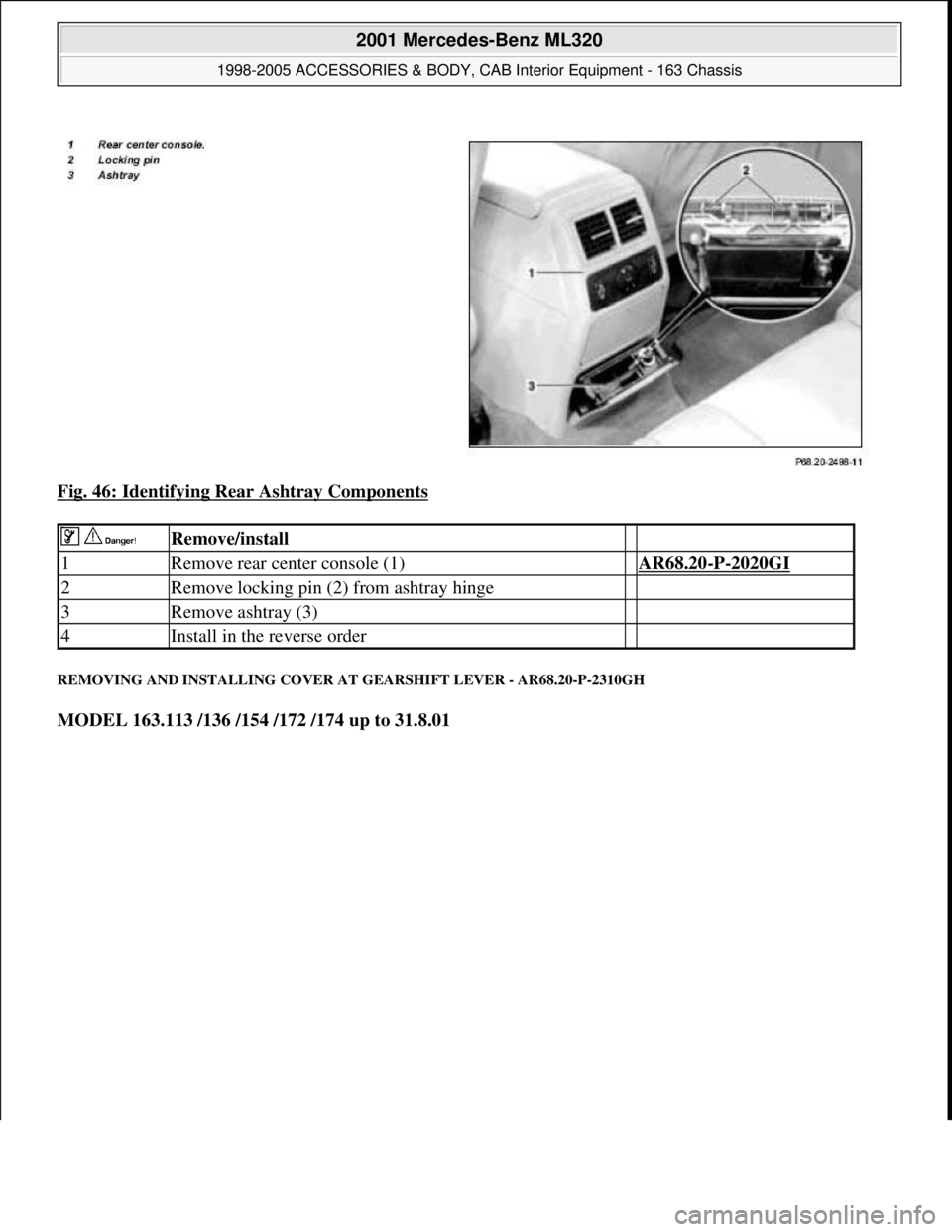
Fig. 46: Identifying Rear Ashtray Components
REMOVING AND INSTALLING COVER AT GEARSHIFT LEVER - AR68.20-P-2310GH
MODEL 163.113 /136 /154 /172 /174 up to 31.8.01
Remove/install
1Remove rear center console (1) AR68.20-P-2020GI
2Remove locking pin (2) from ashtray hinge
3Remove ashtray (3)
4Install in the reverse order
2001 Mercedes-Benz ML320
1998-2005 ACCESSORIES & BODY, CAB Interior Equipment - 163 Chassis
me
Saturday, October 02, 2010 3:35:22 PMPage 50 © 2006 Mitchell Repair Information Company, LLC.
Page 3569 of 4133

Fig. 47: Identifying Gearshift Lever Cover Components
Remove/install
1Remove plastic frame (1) upward Fig.
6
2Remove covering in stowage compartment (2) Fastened with pin.
3Remove center console insert (3) Remove screws (2 each)
from insert floor
4Press cover (4) out of catch in center console at rear and
sides with long wedge Fig.
6
5Disconnect connectors (5) from center console switch
group (S21)
6Install in the reverse order
2001 Mercedes-Benz ML320
1998-2005 ACCESSORIES & BODY, CAB Interior Equipment - 163 Chassis
me
Saturday, October 02, 2010 3:35:22 PMPage 51 © 2006 Mitchell Repair Information Company, LLC.
Page 3570 of 4133

Fig. 48: Identifying Long Wedge (115 589 03 59 00)
REMOVE/INSTALL COVER ON GEARSHIFT LEVER - AR68.20-P-2310GI
MODEL 163.113 /154 /174 #A as of 289565,163.113 #X as of 754620,163.128 /157 /175
Fig. 49: Identifying Cover On Gearshift Lever
Remove/install
1Remove armrest lid (1) AR68.20-P-
2370GH
2Remove plastic screws (5)
3Remove stowage box (2)
Press the pin in the center of the rivet
downwards for about 4 mm; then remove the
rivet from above.
4Remove selector lever paneling Long wedgeFig. 6
5Unscrew bolts (3)
6Remove cover (4) from above Carefully prize open at front (arrows) and at
the sides.
Long wedgeFig. 6
7Detach connector from lower
control panel control module 3 connector.
8Install in the reverse order
2001 Mercedes-Benz ML320
1998-2005 ACCESSORIES & BODY, CAB Interior Equipment - 163 Chassis
me
Saturday, October 02, 2010 3:35:22 PMPage 52 © 2006 Mitchell Repair Information Company, LLC.