MERCEDES-BENZ ML430 1997 Complete Repair Manual
Manufacturer: MERCEDES-BENZ, Model Year: 1997, Model line: ML430, Model: MERCEDES-BENZ ML430 1997Pages: 4133, PDF Size: 88.89 MB
Page 3571 of 4133
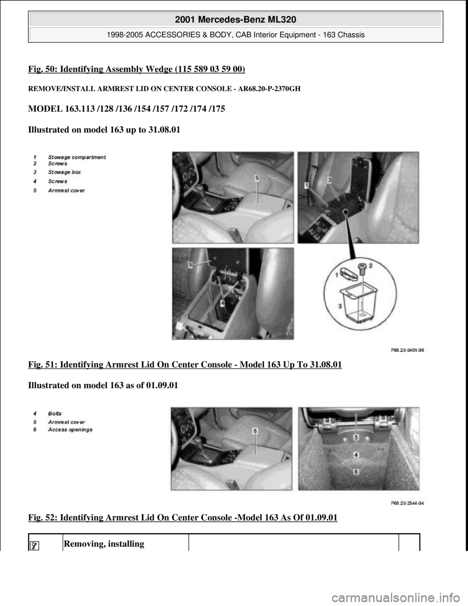
Fig. 50: Identifying Assembly Wedge (115 589 03 59 00)
REMOVE/INSTALL ARMRES T LID ON CENTER CONSOLE - AR68.20-P-2370GH
MODEL 163.113 /128 /136 /154 /157 /172 /174 /175
Illustrated on model 163 up to 31.08.01
Fig. 51: Identifying Armrest Lid On Center Console
- Model 163 Up To 31.08.01
Illustrated on model 163 as of 01.09.01
Fig. 52: Identifying Armrest Lid On Center Console
-Model 163 As Of 01.09.01
Removing, installing
2001 Mercedes-Benz ML320
1998-2005 ACCESSORIES & BODY, CAB In terior Equipment - 163 Chassis
me
Saturday, October 02, 2010 3:35:22 PMPage 53 © 2006 Mitchell Repair Information Company, LLC.
Page 3572 of 4133
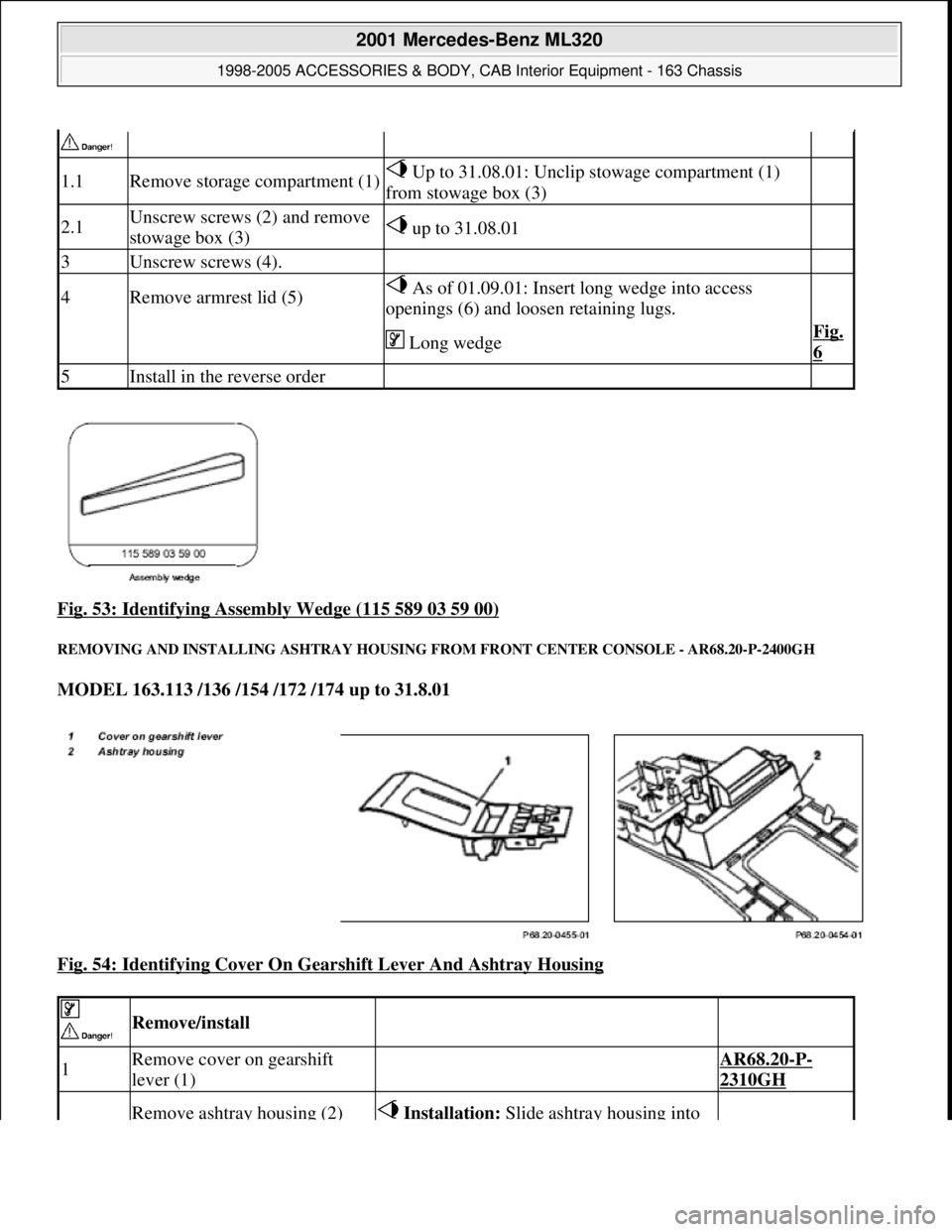
Fig. 53: Identifying Assembly Wedge (115 589 03 59 00)
REMOVING AND INST ALLING ASHTRAY HOUSING FROM FR ONT CENTER CONSOLE - AR68.20-P-2400GH
MODEL 163.113 /136 /154 /172 /174 up to 31.8.01
Fig. 54: Identifying Cover On Gear shift Lever And Ashtray Housing
1.1Remove storage compartment (1) Up to 31.08.01: Unclip stowage compartment (1)
from stowage box (3)
2.1Unscrew screws (2) and remove
stowage box (3) up to 31.08.01
3Unscrew screws (4).
4Remove armrest lid (5) As of 01.09.01: Insert long wedge into access
openings (6) and loosen retaining lugs.
Long wedgeFig.
6
5Install in the reverse order
Remove/install
1Remove cover on gearshift
lever (1) AR68.20-P-
2310GH
Remove ashtray housing (2) Installation: Slide ashtray housing into
2001 Mercedes-Benz ML320
1998-2005 ACCESSORIES & BODY, CAB In terior Equipment - 163 Chassis
me
Saturday, October 02, 2010 3:35:22 PMPage 54 © 2006 Mitchell Repair Information Company, LLC.
Page 3573 of 4133
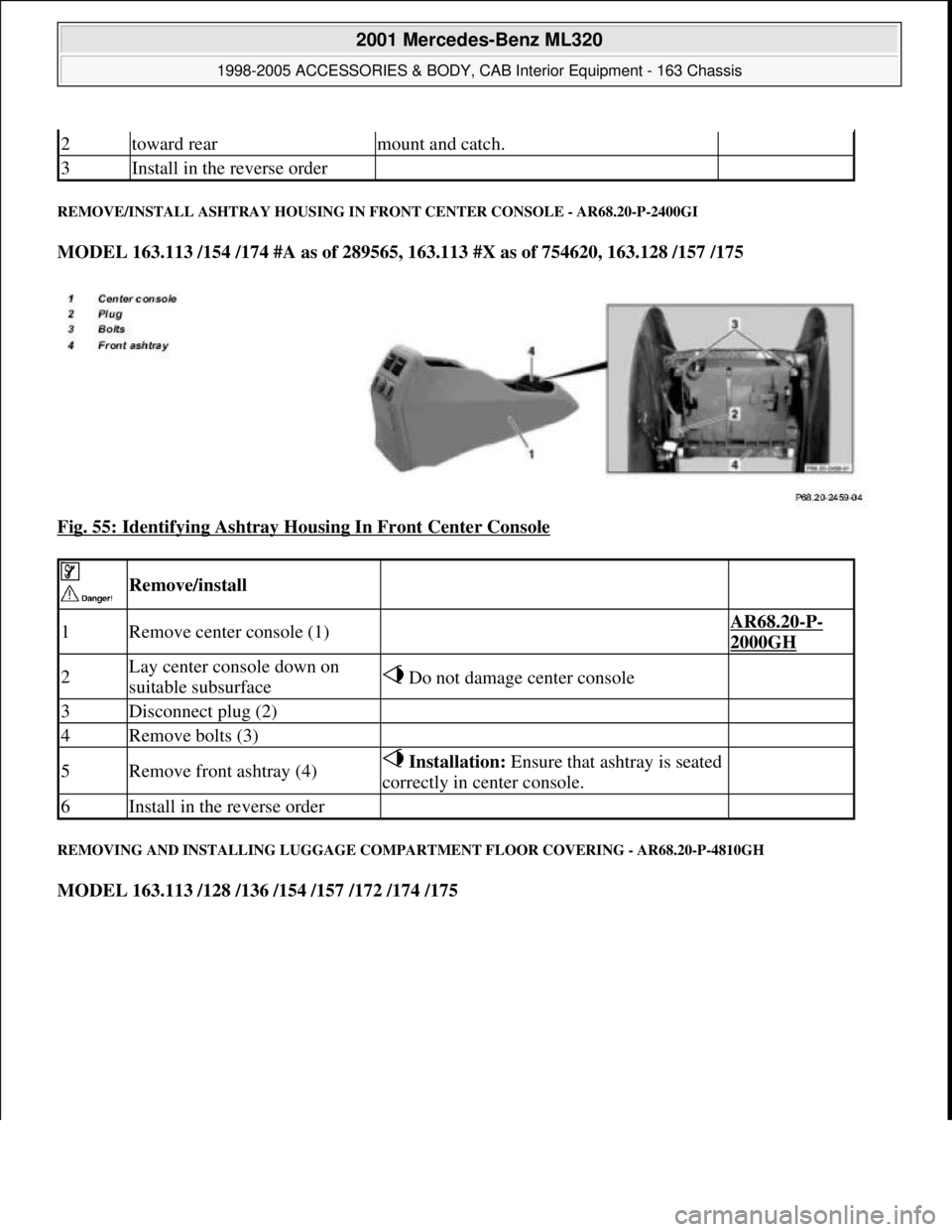
REMOVE/INSTALL ASHTRAY HOUSING IN FRONT CENTER CONSOLE - AR68.20-P-2400GI
MODEL 163.113 /154 /174 #A as of 289565, 163.113 #X as of 754620, 163.128 /157 /175
Fig. 55: Identifying Ashtray Housing In Front Center Console
REMOVING AND INSTALLING LUGGAGE COMPARTMENT FLOOR COVERING - AR68.20-P-4810GH
MODEL 163.113 /128 /136 /154 /157 /172 /174 /175
2toward rearmount and catch.
3Install in the reverse order
Remove/install
1Remove center console (1) AR68.20-P-
2000GH
2Lay center console down on
suitable subsurface Do not damage center console
3Disconnect plug (2)
4Remove bolts (3)
5Remove front ashtray (4) Installation: Ensure that ashtray is seated
correctly in center console.
6Install in the reverse order
2001 Mercedes-Benz ML320
1998-2005 ACCESSORIES & BODY, CAB Interior Equipment - 163 Chassis
me
Saturday, October 02, 2010 3:35:22 PMPage 55 © 2006 Mitchell Repair Information Company, LLC.
Page 3574 of 4133
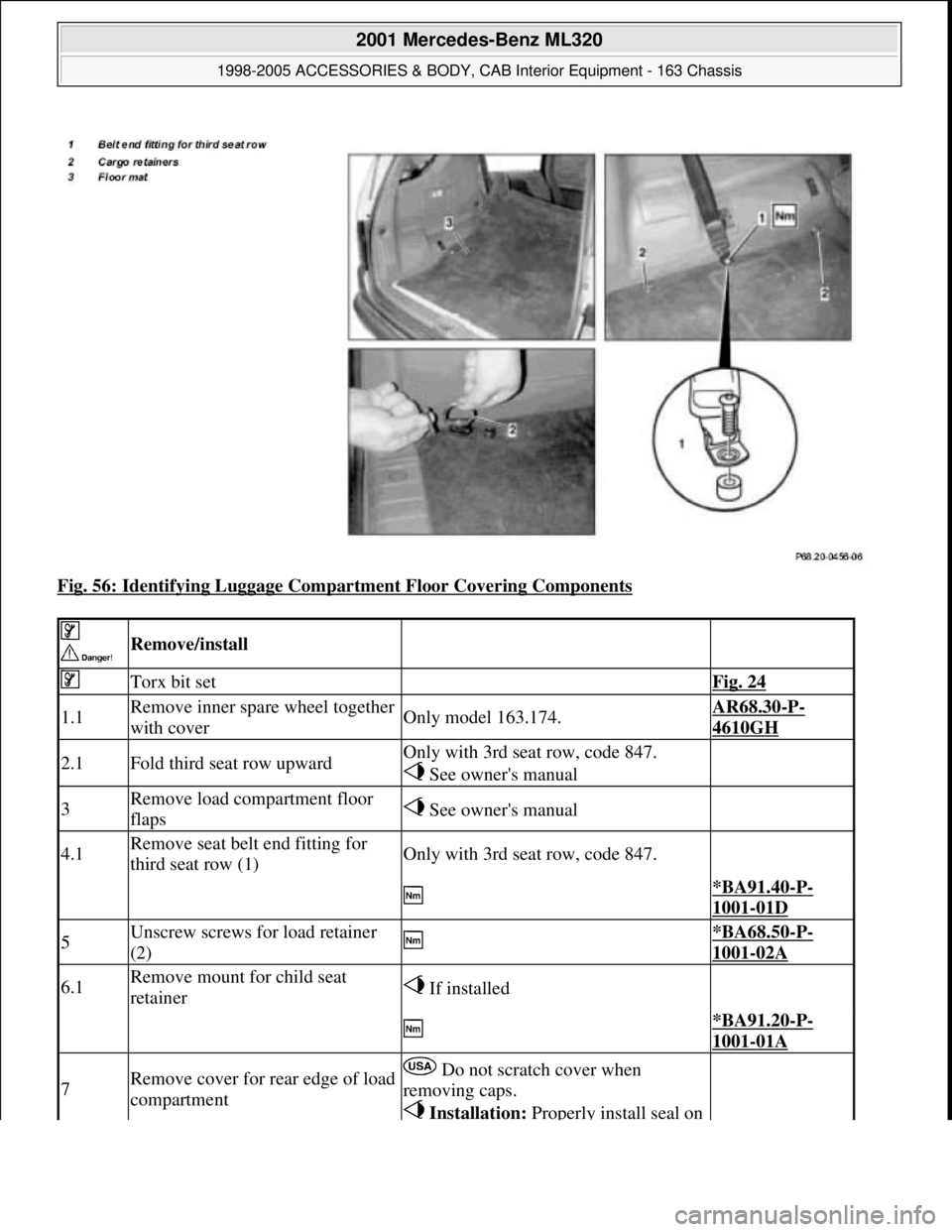
Fig. 56: Identifying Luggage Compartment Floor Covering Components
Remove/install
Torx bit set Fig. 24
1.1Remove inner spare wheel together
with coverOnly model 163.174.AR68.30-P-
4610GH
2.1Fold third seat row upwardOnly with 3rd seat row, code 847.
See owner's manual
3Remove load compartment floor
flaps See owner's manual
4.1Remove seat belt end fitting for
third seat row (1)Only with 3rd seat row, code 847.
*BA91.40-P-
1001-01D
5Unscrew screws for load retainer
(2) *BA68.50-P-
1001-02A
6.1Remove mount for child seat
retainer If installed
*BA91.20-P-
1001-01A
7Remove cover for rear edge of load
compartment Do not scratch cover when
removing caps.
Installation: Properly install seal on
2001 Mercedes-Benz ML320
1998-2005 ACCESSORIES & BODY, CAB Interior Equipment - 163 Chassis
me
Saturday, October 02, 2010 3:35:22 PMPage 56 © 2006 Mitchell Repair Information Company, LLC.
Page 3575 of 4133
Safety belts/emergency tensioning retractors
Luggage nets
Child seats
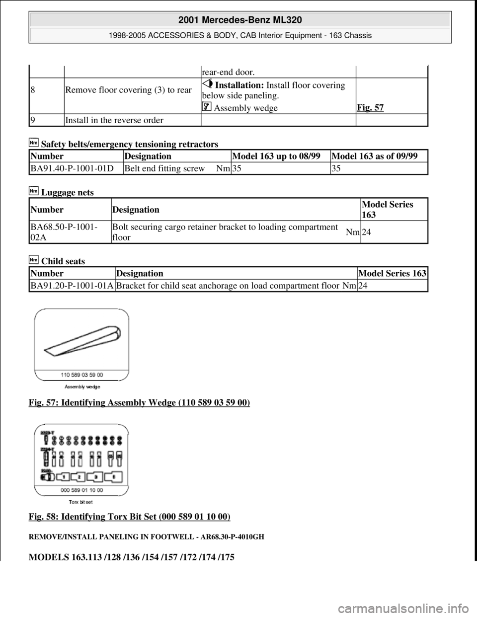
Fig. 57: Identifying Assembly Wedge (110 589 03 59 00)
Fig. 58: Identifying Torx Bit Set (000 589 01 10 00)
REMOVE/INSTALL PANELING IN FOOTWELL - AR68.30-P-4010GH
MODELS 163.113 /128 /136 /154 /157 /172 /174 /175
rear-end door.
8Remove floor covering (3) to rear Installation: Install floor covering
below side paneling.
Assembly wedgeFig. 57
9Install in the reverse order
NumberDesignationModel 163 up to 08/99Model 163 as of 09/99
BA91.40-P-1001-01DBelt end fitting screwNm3535
NumberDesignationModel Series
163
BA68.50-P-1001-
02ABolt securing cargo retainer br acket to loading compartment
floorNm24
NumberDesignationModel Series 163
BA91.20-P-1001-01ABracket for child seat anchorage on load compartment floorNm24
2001 Mercedes-Benz ML320
1998-2005 ACCESSORIES & BODY, CAB In terior Equipment - 163 Chassis
me
Saturday, October 02, 2010 3:35:22 PMPage 57 © 2006 Mitchell Repair Information Company, LLC.
Page 3576 of 4133
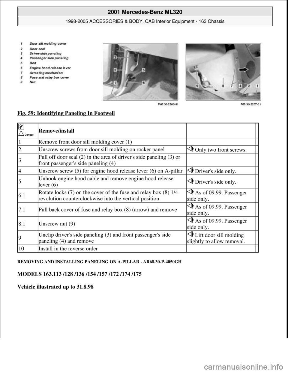
Fig. 59: Identifying Paneling In Footwell
REMOVING AND INSTALLING PANELING ON A-PILLAR - AR68.30-P-4050GH
MODELS 163.113 /128 /136 /154 /157 /172 /174 /175
Vehicle illustrated up to 31.8.98
Remove/install
1Remove front door sill molding cover (1)
2Unscrew screws from door sill molding on rocker panel Only two front screws.
3Pull off door seal (2) in the area of driver's side paneling (3) or
front passenger's side paneling (4)
4Unscrew screw (5) for engine hood release lever (6) on A-pillar Driver's side only.
5Unhook engine hood cable and remove engine hood release
lever (6) Driver's side only.
6.1Rotate locks (7) on the cover of the fuse and relay box (8) 1/4
revolution counterclockwise into the vertical position As of 09.99. Passenger
side only.
7.1Pull back cover of fuse and relay box (8) (arrow) and remove As of 09.99. Passenger
side only.
8.1Unscrew nut (9) As of 09.99. Passenger
side only.
9Unclip driver's side paneling (3) and front passenger's side
paneling (4) and remove Lift door sill molding
slightly to allow removal.
10Install in the reverse order
2001 Mercedes-Benz ML320
1998-2005 ACCESSORIES & BODY, CAB Interior Equipment - 163 Chassis
me
Saturday, October 02, 2010 3:35:22 PMPage 58 © 2006 Mitchell Repair Information Company, LLC.
Page 3577 of 4133
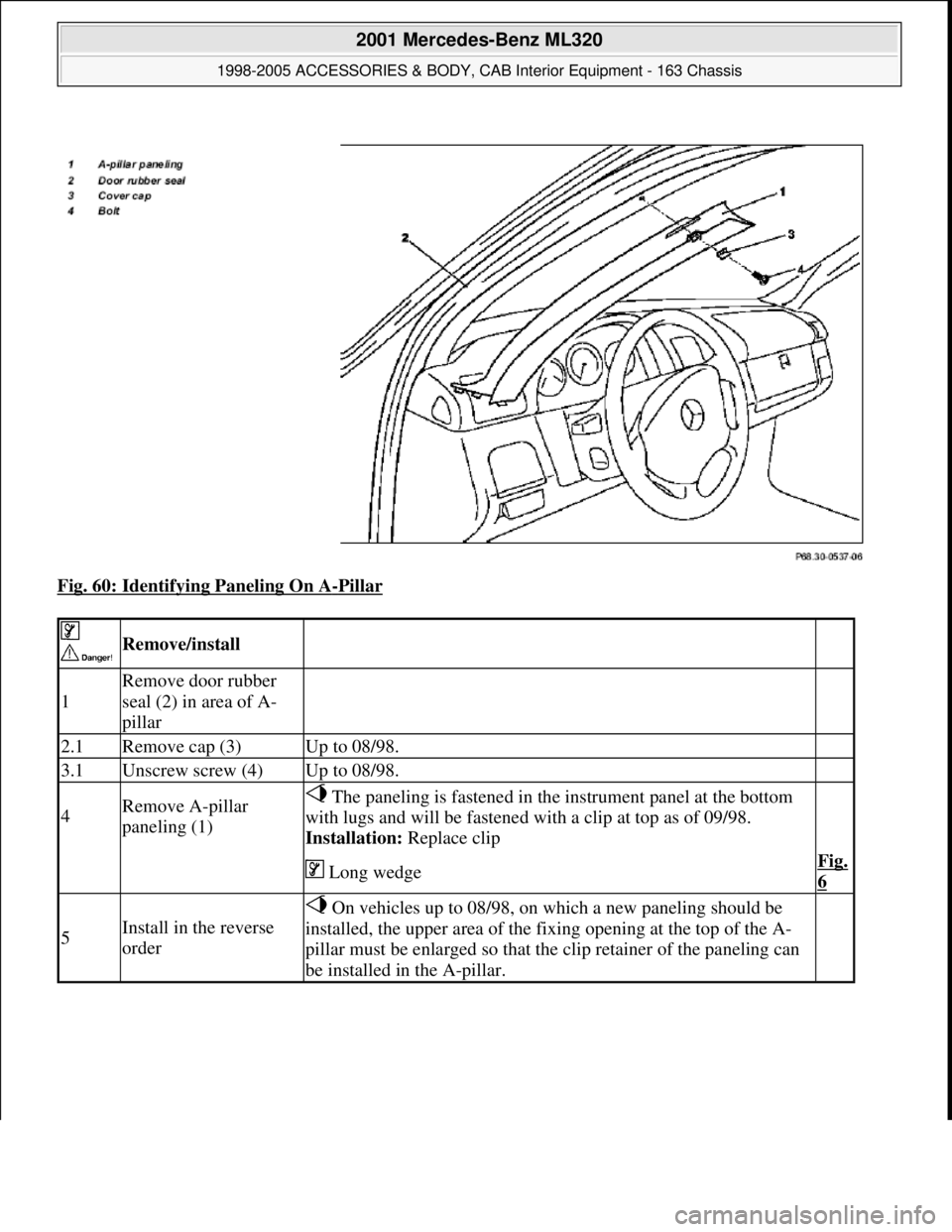
Fig. 60: Identifying Paneling On A-Pillar
Remove/install
1
Remove door rubber
seal (2) in area of A-
pillar
2.1Remove cap (3)Up to 08/98.
3.1Unscrew screw (4)Up to 08/98.
4Remove A-pillar
paneling (1) The paneling is fastened in the instrument panel at the bottom
with lugs and will be fastened with a clip at top as of 09/98.
Installation: Replace clip
Long wedgeFig.
6
5Install in the reverse
order
On vehicles up to 08/98, on which a new paneling should be
installed, the upper area of the fixing opening at the top of the A-
pillar must be enlarged so that the clip retainer of the paneling can
be installed in the A-pillar.
2001 Mercedes-Benz ML320
1998-2005 ACCESSORIES & BODY, CAB Interior Equipment - 163 Chassis
me
Saturday, October 02, 2010 3:35:22 PMPage 59 © 2006 Mitchell Repair Information Company, LLC.
Page 3578 of 4133
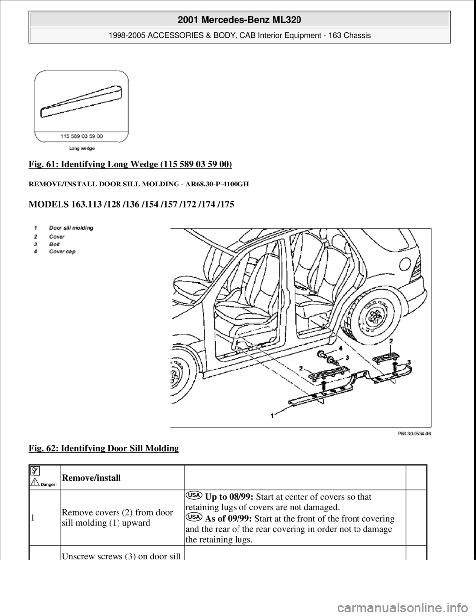
Fig. 61: Identifying Long Wedge (115 589 03 59 00)
REMOVE/INSTALL DOOR SILL MOLDING - AR68.30-P-4100GH
MODELS 163.113 /128 /136 /154 /157 /172 /174 /175
Fig. 62: Identifying Door Sill Molding
Remove/install
1Remove covers (2) from door
sill molding (1) upward
Up to 08/99: Start at center of covers so that
retaining lugs of c overs are not damaged.
As of 09/99: Start at the front of the front covering
and the rear of the rear covering in order not to damage
the retaining lugs.
Unscrew screws (3) on door sill
2001 Mercedes-Benz ML320
1998-2005 ACCESSORIES & BODY, CAB In terior Equipment - 163 Chassis
me
Saturday, October 02, 2010 3:35:22 PMPage 60 © 2006 Mitchell Repair Information Company, LLC.
Page 3579 of 4133
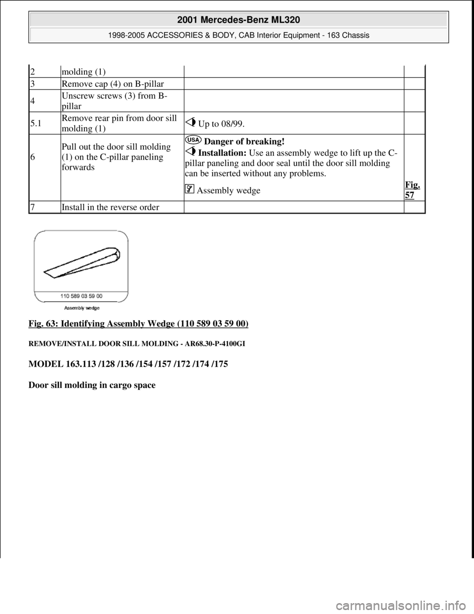
Fig. 63: Identifying Assembly Wedge (110 589 03 59 00)
REMOVE/INSTALL DOOR SILL MOLDING - AR68.30-P-4100GI
MODEL 163.113 /128 /136 /154 /157 /172 /174 /175
Door sill molding in cargo space
2molding (1)
3Remove cap (4) on B-pillar
4Unscrew screws (3) from B-
pillar
5.1Remove rear pin from door sill
molding (1) Up to 08/99.
6
Pull out the door sill molding
(1) on the C-pillar paneling
forwards Danger of breaking!
Installation: Use an assembly wedge to lift up the C-
pillar paneling and door seal until the door sill molding
can be inserted without any problems.
Assembly wedgeFig.
57
7Install in the reverse order
2001 Mercedes-Benz ML320
1998-2005 ACCESSORIES & BODY, CAB Interior Equipment - 163 Chassis
me
Saturday, October 02, 2010 3:35:22 PMPage 61 © 2006 Mitchell Repair Information Company, LLC.
Page 3580 of 4133

Fig. 64: Identifying Caps And Door Sill Molding
PREPARE HEADLINER FOR INSTALLING HANDLES - AR68.30-P-4300-01GH
Models 163.113/136/154/172 up to 31.8.01
When aligning the template, ensure that the arrow is pointing in direction of travel and the correct template
is used for each side.
1. Align template at cutouts provided.
2. Mark cutouts for grab handles.
3. Cut out cutouts for
grab handles.
Remove/install
1Remove cover caps (1) Do not scratch door sill molding.
2Remove screws below caps
3Remove door sill molding (2) Installation: Ensure that sealing rubber is
positioned correctly.
4.1Disconnect connector from electronic
compass Only as of 01.09.00 and with code (245), trip
computer.
5Install in the reverse order
2001 Mercedes-Benz ML320
1998-2005 ACCESSORIES & BODY, CAB Interior Equipment - 163 Chassis
me
Saturday, October 02, 2010 3:35:22 PMPage 62 © 2006 Mitchell Repair Information Company, LLC.