instrument panel MERCEDES-BENZ SLK ROADSTER 2014 Owners Manual
[x] Cancel search | Manufacturer: MERCEDES-BENZ, Model Year: 2014, Model line: SLK ROADSTER, Model: MERCEDES-BENZ SLK ROADSTER 2014Pages: 357, PDF Size: 10.22 MB
Page 17 of 357
Important safety notes .................... 41
Pets in the vehicle ........................... 59
PRE-SAFE® (anticipatory occu-
pant protection) ............................... 50
Odometer
see Trip meter
Oil
see Engine oil
On-board computer
AMG menu .....................................2 19
Assistance menu ........................... 210
Audio menu ................................... 207
Convenience submenu .................. 217
Display messages .......................... 222
Displaying a service message ....... .285
DISTRONIC PLUS ........................... 177
Factory setting submenu .............. .218
Important safety notes .................. 200
Instrument cluster submenu .......... 213
Light submenu ............................... 214
Menu overview .............................. 203
Message memory .......................... 222
Navigation menu ............................ 205
Operating the TV ............................ 208
Operating video DVD ..................... 207
Operation ....................................... 201
RACETIMER ................................... 219
Service menu ................................. 212
Settings menu ............................... 213
Standard displa y............................ 204
Telephone menu ............................ 208
Trip menu ...................................... 204
Vehicle submenu ........................... 216
Operating instructions
Vehicle equipment ........................... 22
Operating safety
Declaration of conformity ................ 23
Important safety note ...................... 22
Operating system
see On-board computer
Outside temperature display ........... 201
Overhead control panel ...................... 36P
Paint code .......................................... 342
Paintwork (cleaning instructions) ... 288
Panic alarm .......................................... 40 Park Assist
Parking Guidance ........................... 188
Parking
Important safety notes .................. 162
Parking brake ................................ 163
Position of exterior mirror, front-
passenger side ............................... 105
see PARKTRONIC
Parking aid
see Exterior mirrors
see PARKTRONIC
Parking assistance
see PARKTRONIC
Parking brake
Display message ............................ 226
Electric parking brake .................... 163
Warning lamp ................................. 257
Parking Guidance
Display message ............................ 239
Important safety notes .................. 188
Parking lamps
Changing bulbs .............................. 119
Display message ............................ 233
Switching on/of f........................... 112
Parking lamps (changing bulbs) ...... 119
PARKTRONIC
Deactivating/activating ................. 187
Driving system ............................... 185
Function/note s............................. 185
Important safety notes .................. 185
Problem (fault) ............................... 188
Sensor rang e................................. 185
Warning display ............................. 186
PASSENGER AIR BAG OFF
Indicator lamp .................................. 41
Problems (malfunctions) .................. 56
Petrol .................................................. 344
Pets in the vehicle ............................... 59
Plastic trim (cleaning instruc-
tions) .................................................. 290
Power windows
see Side windows
PRE-SAFE® (anticipatory occupant
protection)
Operation ......................................... 50
PRE-SAFE® (preventive occupant
safety system)
Display message ............................ 230 14
Index
Page 30 of 357
Cockpit
................................................. 28
Instrument cluster ..............................30
Multifunction steering wheel .............33
Centre console .................................... 34
Overhead control panel ......................36
Door control panel .............................. 37 27At a glance
Page 31 of 357
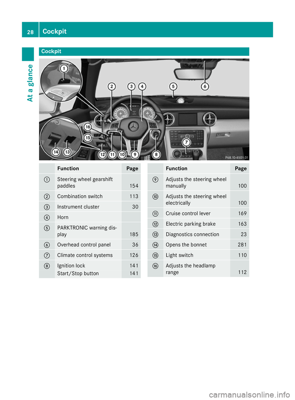
Cockpit
Function Page
:
Steering wheel gearshift
paddles
154
;
Combination switch 113
=
Instrument cluster 30
?
Horn
A
PARKTRONIC warning dis-
play
185
B
Overhead control panel 36
C
Climate control systems 126
D
Ignition lock 141
Start/Stop button 141 Function Page
E
Adjusts the steering wheel
manually
100
F
Adjusts the steering wheel
electrically
100
G
Cruise control lever 169
H
Electric parking brake 163
I
Diagnostics connection 23
J
Opens the bonnet 281
K
Light switch 110
L
Adjusts the headlamp
range
11228
CockpitAt a glance
Page 32 of 357
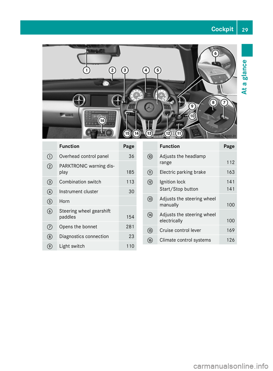
Function Page
:
Overhead control panel 36
;
PARKTRONIC warning dis-
play 185
=
Combination switch 113
?
Instrument cluster 30
A
Horn
B
Steering wheel gearshift
paddles
154
C
Opens the bonnet 281
D
Diagnostics connection 23
E
Light switch 110 Function Page
F
Adjusts the headlamp
range
112
G
Electric parking brake 163
H
Ignition lock 141
Start/Stop button 141
I
Adjusts the steering wheel
manually
100
J
Adjusts the steering wheel
electrically
100
K
Cruise control lever 169
L
Climate control systems 126Cockpit
29At a glance
Page 119 of 357
this, or in similar situations, the automatic
main-beam headlamps will not be deactivated or activated regardless. There is a risk of an
accident.
Always carefully observe the traffic conditions
and switch off the main-beam headlamps in
good time.
Adaptive Highbeam Assist cannot take into
account road, weather or traffic conditions.
Adaptive Highbeam Assist is only an aid. You are responsible for adjusting the vehicle's
lighting to the prevailing light, visibility and
traffic conditions.
In particular, the detection of obstacles can
be restricted if there is:
R poor visibility, e.g. due to fog, heavy rain or
snow
R dirt on the sensors or if the sensors are
obscured
Activating Adaptive Highbeam Assist X
To switch on: turn the light switch to Ã.
X Press the combination switch beyond the
pressure point in the direction of arrow :.
The _ indicator lamp in the multifunc-
tion display lights up when it is dark and the light sensor activates the dipped-beam
headlamps.
If you are driving at speeds above 25 km/h:
The headlamp range is set automatically
depending on the distance between the
vehicle and other road users.
If you are driving at speeds above approx-
imately 30 km/h and no other road users
are recognised:
The main-beam headlamps are switched on
automatically. The Kindicator lamp in
the instrument cluster also lights up.
If you are driving at speeds below 25 km/h
or other road users are recognised or the
roads are adequately lit:
The main-beam headlamps are switched off automatically. The Kindicator lamp in
the instrument cluster goes out. The _indicator lamp in the multifunction display
remains lit.
X To switch off: move the combination
switch back to its normal position or move the light switch to another position.
The _ indicator lamp in the multifunc-
tion display goes out. Headlamps misted up on the inside
Certain climatic and physical conditions may
cause moisture to form in the headlamp. This
moisture does not affect the functionality of
the headlamp. Interior lighting
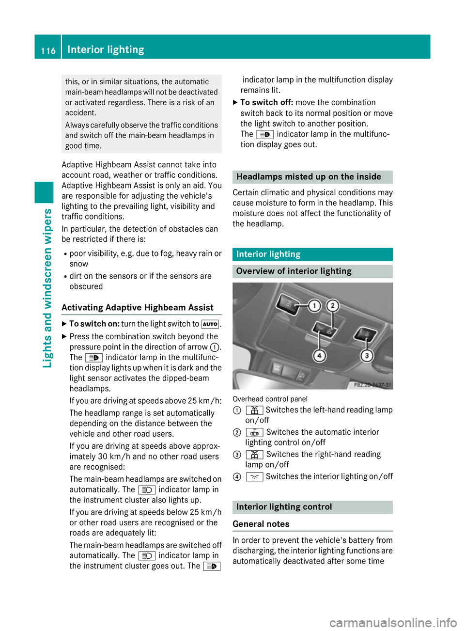
Overview of interior lighting
Overhead control panel
:
p Switches the left-hand reading lamp
on/off
; | Switches the automatic interior
lighting control on/off
= p Switches the right-hand reading
lamp on/off
? c Switches the interior lighting on/off Interior lighting control
General notes In order to prevent the vehicle's battery from
discharging, the interior lighting functions are
automatically deactivated after some time 116
Interior lightingLights and
windscreen wipers
Page 203 of 357
Useful information
i This Owner's Manual describes all mod-
els, series and optional equipment for your
vehicle that were available at the time of
going to press. National variations are pos- sible. Note that your vehicle may not be
equipped with all of the functions descri-
bed. This is also the case for systems and
functions relevant to safety.
i Read the information on qualified special-
ist workshops: (Y page 24). Important safety notes
G
WARNING
Operating the integrated information systems and communications equipment in the vehicle
while driving will distract you from traffic con-
ditions. You could then lose control of the
vehicle. There is a risk of an accident.
Only operate these devices if road traffic con-
ditions permit. If you are unsure about the
surrounding conditions, pull over to a safe
location and make entries only while the vehi-
cle is stationary.
You must observe the legal requirements for
the country in which you are currently driving when operating the on-board computer. G
WARNING
If the instrument cluster has failed or mal-
functioned, you may not recognise function
restrictions relevant to safety. The operating
safety of your vehicle may be impaired. There is a risk of an accident.
Drive on carefully. Have the vehicle checked
at a qualified specialist workshop immedi-
ately.
The on-board computer only shows messages
or warnings from certain systems in the mul- tifunction display. You should therefore make
sure your vehicle is operating safely at all times. Otherwise, a vehicle that is not oper-
ating safely may cause an accident.
If the operating safety of your vehicle is
impaired, park the vehicle safely as soon as
possible. Consult a qualified specialist work-
shop.
For an overview, see the instrument panel
illustration (Y
page 30). Displays and operation
Instrument cluster lighting
The lighting in the instrument cluster, in the
displays and the controls in the vehicle inte-
rior can be adjusted using the brightness con-
trol knob.
The brightness control knob is on the bottom left of the instrument cluster (Y page 30).
X Turn the brightness control knob anti-
clockwise or clockwise.
If the light switch is set to Ã,Tor
L, the brightness is dependant upon
the brightness of the ambient light.
i The light sensor in the instrument cluster
automatically controls the brightness of
the multifunction display.
In daylight, the displays in the instrument
cluster are not lit. Coolant temperature gauge
G
WARNING
If you open the bonnet while the engine is
overheating or while there is a fire in the
engine compartment, you could come into
contact with hot gases or other leaking ser-
vice products. There is a danger of injury.
Allow an overheating engine to cool down
before opening the bonnet. If there is a fire in the engine compartment, leave the bonnet
closed and notify the fire brigade. 200
Displays and operationOn-board computer and displays
Page 204 of 357
The coolant temperature gauge is in the
instrument cluster on the right-hand side
(Y page 30).
Under normal operating conditions and with
the specified coolant level, the coolant tem-
perature may rise to 120 †.
At high outside temperatures and when driv-
ing uphill, the coolant temperature may rise
to the end of the scale. Rev counter
! Do not drive in the overrevving range.
Doing so will damage the engine.
The red band in the rev counter indicates the engine's overrevving range.
The fuel supply is interrupted to protect the
engine when the red band is reached. Outside temperature display
You should pay special attention to road con-
ditions when temperatures are around the
freezing point.
Bear in mind that the outside temperature
display indicates the temperature measured
and does not record the road temperature.
The outside temperature display is in the mul- tifunction display (Y page 202).
Changes in the outside temperature are dis-
played after a short delay. Speedometer with segments
The segments in the speedometer indicate
which speed range is available.
R Cruise control activated (Y page 168):
The segments light up from the stored
speed to the maximum speed.
R Variable SPEEDTRONIC activated
(Y page 180):
The segments light up from the start of the
scale to the selected limit speed.
R DISTRONIC PLUS activated (Y page 171):One or two segments in the set speed
range light up.
R DISTRONIC PLUS detects a vehicle in front:
The segments between the speed of the
vehicle in front and the stored speed light
up. Operating the on-board computer
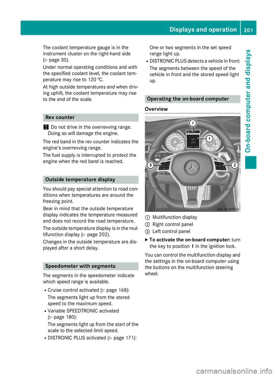
Overview :
Multifunction display
; Right control panel
= Left control panel
X To activate the on-board computer: turn
the key to position 1in the ignition lock.
You can control the multifunction display and
the settings in the on-board computer using
the buttons on the multifunction steering
wheel. Displays and operation
201On-board computer and displays Z