fuel MERCEDES-BENZ SPRINTER 2005 Service Owner's Manual
[x] Cancel search | Manufacturer: MERCEDES-BENZ, Model Year: 2005, Model line: SPRINTER, Model: MERCEDES-BENZ SPRINTER 2005Pages: 1232, PDF Size: 39.23 MB
Page 174 of 1232
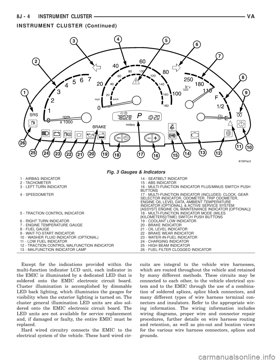
Except for the indications provided within the
multi-function indicator LCD unit, each indicator in
the EMIC is illuminated by a dedicated LED that is
soldered onto the EMIC electronic circuit board.
Cluster illumination is accomplished by dimmable
LED back lighting, which illuminates the gauges for
visibility when the exterior lighting is turned on. The
cluster general illumination LED units are also sol-
dered onto the EMIC electronic circuit board. The
LED units are not available for service replacement
and, if damaged or faulty, the entire EMIC must be
replaced.
Hard wired circuitry connects the EMIC to the
electrical system of the vehicle. These hard wired cir-cuits are integral to the vehicle wire harnesses,
which are routed throughout the vehicle and retained
by many different methods. These circuits may be
connected to each other, to the vehicle electrical sys-
tem and to the EMIC through the use of a combina-
tion of soldered splices, splice block connectors, and
many different types of wire harness terminal con-
nectors and insulators. Refer to the appropriate wir-
ing information. The wiring information includes
wiring diagrams, proper wire and connector repair
procedures, further details on wire harness routing
and retention, as well as pin-out and location views
for the various wire harness connectors, splices and
grounds.
Fig. 3 Gauges & Indicators
1 - AIRBAG INDICATOR 14 - SEATBELT INDICATOR
2 - TACHOMETER 15 - ABS INDICATOR
3 - LEFT TURN INDICATOR 16 - MULTI-FUNCTION INDICATOR PLUS/MINUS SWITCH PUSH
BUTTONS
4 - SPEEDOMETER 17 - MULTI-FUNCTION INDICATOR (INCLUDES: CLOCK, GEAR
SELECTOR INDICATOR, ODOMETER, TRIP ODOMETER,
ENGINE OIL LEVEL DATA, AMBIENT TEMPERATURE
INDICATOR [OPTIONAL], & ACTIVE SERVICE SYSTEM
[ASSYST] ENGINE OIL MAINTENANCE INDICATOR [OPTIONAL])
5 - TRACTION CONTROL INDICATOR 18 - MULTI-FUNCTION INDICATOR MODE (MILES
[KILOMETERS]/TIME) SWITCH PUSH BUTTONS
6 - RIGHT TURN INDICATOR 19 - COOLANT LOW INDICATOR
7 - ENGINE TEMPERATURE GAUGE 20 - BRAKE INDICATOR
8 - FUEL GAUGE 21 - OIL LEVEL INDICATOR
9 - WAIT-TO-START INDICATOR 22 - BRAKE WEAR INDICATOR
10 - WASHER FLUID INDICATOR (OPTIONAL) 23 - WATER-IN-FUEL INDICATOR
11 - LOW FUEL INDICATOR 24 - CHARGING INDICATOR
12 - TRACTION CONTROL MALFUNCTION INDICATOR 25 - HIGH BEAM INDICATOR
13 - MALFUNCTION INDICATOR LAMP 26 - FUEL FILTER CLOGGED INDICATOR
8J - 4 INSTRUMENT CLUSTERVA
INSTRUMENT CLUSTER (Continued)
Page 175 of 1232
The EMIC modules for this model are serviced only
as complete units. The EMIC module cannot be
adjusted or repaired. If a gauge, an LED indicator,
the multi-fuction indicator LCD unit, an electronic
tone generator, the electronic circuit board, the cir-
cuit board hardware, the cluster overlay, the cluster
housing, the cluster hood, the cluster lens, or the
cluster rear cover are damaged or faulty, the entire
EMIC module must be replaced.
OPERATION
The ElectroMechanical Instrument Cluster (EMIC)
is designed to allow the vehicle operator to monitor
the conditions of many of the vehicle components and
operating systems. The gauges, meters and indicators
in the EMIC provide valuable information about the
powertrain, fuel and emissions systems, cooling sys-
tem, lighting systems, safety systems and many
other convenience items. The EMIC is installed in
the instrument panel so that all of these monitors
can be easily viewed by the vehicle operator when
driving, while still allowing relative ease of access for
service. The microprocessor-based EMIC hardware
and software uses various inputs to control the
gauges and indicators visible on the face of the clus-
ter. Some of these inputs are hard wired, but many
are in the form of electronic messages that are trans-
mitted by other electronic modules over the Control-
ler Area Network (CAN) data bus network. (Refer to
8 - ELECTRICAL/ELECTRONIC CONTROL MOD-
ULES/COMMUNICATION - OPERATION).
The EMIC microprocessor smooths the input data
using algorithms to provide gauge readings that are
accurate, stable and responsive to operating condi-
tions. These algorithms are designed to provide
gauge readings during normal operation that are con-
sistent with customer expectations. However, when
abnormal conditions exist such as high coolant tem-
perature, the algorithm can drive the gauge pointer
to an extreme position and the microprocessor can
sound a chime through the on-board audible tone
generator to provide distinct visual and audible indi-
cations of a problem to the vehicle operator. The
instrument cluster circuitry also provides audible
turn signal and hazard warning support by emulat-
ing the ªtickingº sound associated with a conven-
tional electro-mechanical flasher using a contactless
relay. The relay will also provide an indication of a
turn signal failure by sounding at double the usual
frequency. Each audible warning is provided to the
vehicle operator to supplement a visual indication.
The EMIC circuitry operates on battery current
received through a non-switched fused B(+) circuit,
and on a fused ignition switch output circuit. The
EMIC circuitry is grounded through a ground circuit
and take out of the frame wire harness with an eye-let terminal connector that is secured to a stud by a
nut at a ground location on the dash panel just for-
ward of the instrument cluster. Separate switched
ground inputs from the key-in ignition switch and
the front door jamb switches provide wake-up signals
to the EMIC circuitry. This arrangement allows the
EMIC to provide some features regardless of the igni-
tion switch position, while other features will operate
only with the ignition switch in the On position.
Proper diagnosis and testing of the EMIC, the
CAN data bus, the data bus electronic message
inputs to and outputs from the EMIC, as well as the
retrieval or erasure of a Diagnostic Trouble Code
(DTC) requires the use of a DRBIIItscan tool. Refer
to the appropriate diagnostic information. See the
owner's manual in the vehicle glove box for more
information on the features, use and operation of the
EMIC.
GAUGES
All gauges receive battery current through the
EMIC circuitry only when the instrument cluster
detects the ignition switch is in the On position. With
the ignition switch in the Off position, battery cur-
rent is not supplied to any gauges and the EMIC cir-
cuitry is programmed to move all of the gauge
needles back to the low end of their respective scales.
Therefore, the gauges do not accurately indicate any
vehicle condition unless the ignition switch is in the
On position.
All of the EMIC gauges are air core magnetic
units. Two fixed electromagnetic coils are located
within each gauge. These coils are wrapped at right
angles to each other around a movable permanent
magnet. The movable magnet is suspended within
the coils on one end of a pivot shaft, while the gauge
needle is attached to the other end of the shaft. One
of the coils has a fixed current flowing through it to
maintain a constant magnetic field strength. Current
flow through the second coil changes, which causes
changes in its magnetic field strength. The current
flowing through the second coil is changed by the
EMIC circuitry in response to messages received over
the CAN data bus. The gauge needle moves as the
movable permanent magnet aligns itself to the
changing magnetic fields created around it by the
electromagnets.
Proper diagnosis and testing of the gauges, the
CAN data bus and the electronic data bus message
inputs to the EMIC that control each gauge require
the use of a DRBIIItscan tool. Refer to the appro-
priate diagnostic information. Specific operation
details for each gauge may be found elsewhere in
this service information.
VAINSTRUMENT CLUSTER 8J - 5
INSTRUMENT CLUSTER (Continued)
Page 176 of 1232
INDICATORS
Indicators are located in various positions within
the EMIC and are all connected to the EMIC elec-
tronic circuit board. The ambient temperature indica-
tor (optional), brake indicator, brake wear indicator,
charging indicator, coolant low indicator, high beam
indicator, low fuel indicator, seatbelt indicator, turn
signal indicators, and washer fluid indicator operate
based upon hard wired inputs to the EMIC. The air-
bag (SRS) indicator is normally controlled by a hard
wired input from the Airbag Control Module (ACM);
however, if the EMIC sees an abnormal or no input
from the ACM, it will automatically turn the airbag
indicator On until the hard wired input from the
ACM has been restored. The Malfunction Indicator
Lamp (MIL) is normally controlled by CAN data bus
messages from the Engine Control Module (ECM);
however, if the EMIC loses CAN data bus communi-
cation, the EMIC circuitry will automatically turn
the MIL on until CAN data bus communication is
restored. The EMIC uses CAN data bus messages
from the ECM, the ACM, and the Controller Antilock
Brake to control all of the remaining indicators.
The various EMIC indicators are controlled by dif-
ferent strategies; some receive battery feed from the
EMIC circuitry and have a switched ground, while
others are grounded through the EMIC circuitry and
have a switched battery feed. However, all indicators
are completely controlled by the EMIC microproces-
sor based upon various hard wired and electronic
message inputs. Except for the indications provided
by the multi-function indicator Liquid Crystal Dis-
play (LCD) unit, all indicators are illuminated at a
fixed intensity, which is not affected by the selected
illumination intensity of the EMIC general illumina-
tion lamps.
The hard wired indicator inputs may be diagnosed
using conventional diagnostic methods. However,
proper testing of the EMIC circuitry and the CAN
bus message controlled indicators requires the use of
a DRBIIItscan tool. Refer to the appropriate diag-
nostic information. Specific details of the operation
for each indicator may be found elsewhere in this
service information.
CLUSTER ILLUMINATION
The EMIC has several general illumination lamps
that are illuminated when the exterior lighting is
turned on with the multi-function switch. The illumi-
nation intensity of these lamps is adjusted by a dim-
ming level input received from the multi-function
indicator ª+º (plus) and ª±º (minus) switch push but-
tons that extend through the lower edge of the clus-
ter lens below the right end of the multi-function
indicator. When the exterior lighting is turned Off,
the display is illuminated at maximum brightness.When the exterior lighting is turned On and the
transmission gear selector is in the Park position,
depressing the plus switch push button brightens the
display lighting, and depressing the minus switch
push button dims the display lighting. The EMIC
also provides a Pulse-Width Modulated (PWM) panel
lamps dimmer output that can be used to synchro-
nize the illumination lighting levels of external illu-
mination lamps (up to about 23 to 30 watts) with
that of the EMIC.
The hard wired multi-function switch input and
the EMIC panel lamps dimmer output may be diag-
nosed using conventional diagnostic methods. How-
ever, proper testing of the PWM control of the EMIC
and the electronic dimming level inputs from the
multi-function indicator push buttons requires the
use of a DRBIIItscan tool. Refer to the appropriate
diagnostic information.
INPUT AND OUTPUT CIRCUITS
HARD WIRED INPUTS
The hard wired inputs to the EMIC include the fol-
lowing:
NOTE: Final approved circuit names were not yet
available at the time this information was compiled.
²Airbag Indicator Driver
²Ambient Temperature Sensor Signal
(Optional)
²Brake Wear Indicator Sense
²Charging Indicator Driver
²Coolant Level Switch Sense
²Front Door Jamb Switch Sense
²Fuel Level Sensor Signal
²Fused B(+)
²Fused Ignition Switch Output
²High Beam Indicator Driver
²Key-In Ignition Switch Sense
²Left Turn Signal
²Park Brake Switch Sense
²Right Turn Signal
²Seat Belt Switch Sense
²Washer Fluid Switch Sense (Optional)
Refer to the appropriate wiring information for
additional details.
HARD WIRED OUTPUTS
The hard wired outputs of the EMIC include the
following:
NOTE: Final approved circuit names were not yet
available at the time this information was compiled.
²Engine Running Relay Control
²Panel Lamps Driver
8J - 6 INSTRUMENT CLUSTERVA
INSTRUMENT CLUSTER (Continued)
Page 177 of 1232
Refer to the appropriate wiring information for
additional details.
GROUNDS
The EMIC receives and supplies a ground path to
several switches and sensors through the following
hard wired circuits:
NOTE: Final approved circuit names were not yet
available at the time this information was compiled.
²Ambient Temperature Sensor Return
(Optional)
²Fuel Level Sensor Return
²Ground
Refer to the appropriate wiring information for
additional details.
COMMUNICATION
The EMIC has provisions for the following commu-
nication circuits:
NOTE: Final approved circuit names were not yet
available at the time this information was compiled.
²CAN Data Bus - High
²CAN Data Bus - Low
²Diagnostic Serial Communication Interface
(SCI) Data Bus Line
Refer to the appropriate wiring information for
additional details.
DIAGNOSIS AND TESTING - INSTRUMENT
CLUSTER
The hard wired inputs to and outputs from the
instrument cluster may be diagnosed and tested
using conventional diagnostic tools and procedures.
Refer to the appropriate wiring information. The wir-
ing information includes wiring diagrams, proper
wire and connector repair procedures, details of wire
harness routing and retention, connector pin-out
information and location views for the various wire
harness connectors, splices and grounds.
If the instrument cluster is completely inoperative,
be certain to check the fused B(+) circuit fuses and
wiring for the instrument cluster. If the cluster gen-
eral illumination is inoperative, be certain to check
the instrument lighting fuse and the input circuit to
the instrument cluster from the exterior lighting cir-
cuitry of the multi-function switch on the steering
column.
Conventional diagnostic methods may not prove
conclusive in the diagnosis of the instrument cluster.
In order to obtain conclusive testing of the instru-
ment cluster, the Controller Area Network (CAN)
data bus network and all of the electronic modules
that provide inputs to or receive outputs from theinstrument cluster must also be checked. The most
reliable, efficient, and accurate means to diagnose
the instrument cluster, the CAN data bus network,
and the electronic modules that provide inputs to or
receive outputs from the instrument cluster requires
the use of a DRBIIItscan tool and the appropriate
diagnostic information. The DRBIIItscan tool can
provide confirmation that the CAN data bus network
is functional, that all of the modules are sending and
receiving the proper electronic messages over the
CAN data bus, and that the instrument cluster is
receiving the proper hard wired inputs and respond-
ing with the proper hard wired outputs needed to
perform its many functions.
WARNING: ON VEHICLES EQUIPPED WITH AIR-
BAGS, DISABLE THE SUPPLEMENTAL RESTRAINT
SYSTEM BEFORE ATTEMPTING ANY STEERING
WHEEL, STEERING COLUMN, DRIVER AIRBAG,
PASSENGER AIRBAG, SEAT BELT TENSIONER, OR
INSTRUMENT PANEL COMPONENT DIAGNOSIS OR
SERVICE. DISCONNECT AND ISOLATE THE BAT-
TERY NEGATIVE (GROUND) CABLE, THEN WAIT
TWO MINUTES FOR THE SYSTEM CAPACITOR TO
DISCHARGE BEFORE PERFORMING FURTHER
DIAGNOSIS OR SERVICE. THIS IS THE ONLY SURE
WAY TO DISABLE THE SUPPLEMENTAL
RESTRAINT SYSTEM. FAILURE TO TAKE THE
PROPER PRECAUTIONS COULD RESULT IN ACCI-
DENTAL SUPPLEMENTAL RESTRAINT DEPLOY-
MENT AND POSSIBLE PERSONAL INJURY.
REMOVAL
WARNING: ON VEHICLES EQUIPPED WITH AIR-
BAGS, DISABLE THE SUPPLEMENTAL RESTRAINT
SYSTEM BEFORE ATTEMPTING ANY STEERING
WHEEL, STEERING COLUMN, DRIVER AIRBAG,
PASSENGER AIRBAG, SEAT BELT TENSIONER, OR
INSTRUMENT PANEL COMPONENT DIAGNOSIS OR
SERVICE. DISCONNECT AND ISOLATE THE BAT-
TERY NEGATIVE (GROUND) CABLE, THEN WAIT
TWO MINUTES FOR THE SYSTEM CAPACITOR TO
DISCHARGE BEFORE PERFORMING FURTHER
DIAGNOSIS OR SERVICE. THIS IS THE ONLY SURE
WAY TO DISABLE THE SUPPLEMENTAL
RESTRAINT SYSTEM. FAILURE TO TAKE THE
PROPER PRECAUTIONS COULD RESULT IN ACCI-
DENTAL SUPPLEMENTAL RESTRAINT DEPLOY-
MENT AND POSSIBLE PERSONAL INJURY.
(1) Disconnect and isolate the battery negative
cable.
(2) Remove the cluster bezel from the instrument
panel. (Refer to 23 - BODY/INSTRUMENT PANEL/
CLUSTER BEZEL - REMOVAL).
VAINSTRUMENT CLUSTER 8J - 7
INSTRUMENT CLUSTER (Continued)
Page 185 of 1232
ENGINE TEMPERATURE
GAUGE
DESCRIPTION
An engine coolant temperature gauge is standard
equipment on all instrument clusters. The engine
coolant temperature gauge is located in the upper
right corner of the instrument cluster, to the right of
the speedometer. The engine coolant temperature
gauge consists of a movable gauge needle or pointer
controlled by the instrument cluster circuitry and a
fixed 45 degree scale on the cluster overlay that
reads left-to-right from 120É C to 40É C for Canadian
vehicles, or from 250É F to 110É F for United States
vehicles. An International Control and Display Sym-
bol icon for ªEngine Coolant Temperatureº is located
on the cluster overlay, directly below the high end of
the scale. Just to the right of the icon, the nomencla-
ture ªÉCº or ªÉFº confirms the unit of measure for the
gauge readings.
The engine coolant temperature gauge graphics are
white against a black field, except for a single red
graduation at the far left (high) end of the gauge
scale, making them clearly visible within the instru-
ment cluster in daylight. When illuminated from
behind by the panel lamps dimmer controlled cluster
illumination lighting with the exterior lamps turned
On, the white graphics appear amber and the red
graphics appear red. The orange gauge needle is
internally illuminated. Gauge illumination is pro-
vided by Light Emitting Diode (LED) units soldered
onto the instrument cluster electronic circuit board.
The engine coolant temperature gauge is serviced as
a unit with the instrument cluster.
OPERATION
The engine coolant temperature gauge gives an
indication to the vehicle operator of the engine cool-
ant temperature. This gauge is controlled by the
instrument cluster circuit board based upon cluster
programming and electronic messages received by
the cluster from the Engine Control Module (ECM)
over the Controller Area Network (CAN) data bus.
The engine coolant temperature gauge is an air core
magnetic unit that receives battery current on the
instrument cluster electronic circuit board when the
instrument cluster detects that the ignition switch is
in the On position. The cluster is programmed to
move the gauge needle back to the low end of the
scale after the ignition switch is turned to the Off
position. The instrument cluster circuitry controls
the gauge needle position and provides the following
features:
²Engine Temperature Normal Message- Each
time the cluster receives a message from the ECMindicating the engine coolant temperature is within
the normal operating range [up to about 120É C (250É
F), the gauge needle is moved to the actual relative
temperature position on the gauge scale.
²Engine Temperature High Message- Each
time the cluster receives a message from the ECM
indicating the engine coolant temperature is high
[above about 120É C (250É F) the gauge needle is
moved into the red warning zone on the gauge scale.
The ECM continually monitors the engine coolant
temperature sensor to determine the engine operat-
ing temperature. The ECM then sends the proper
engine coolant temperature messages to the instru-
ment cluster. If the instrument cluster moves the
engine coolant temperature gauge needle to red area
of the gauge scale, it may indicate that the engine or
the engine cooling system require service. For proper
diagnosis of the engine coolant temperature sensor,
the ECM, the CAN data bus, the electronic message
inputs to the instrument cluster, or the instrument
cluster circuitry that controls the engine coolant tem-
perature gauge, a DRBIIItscan tool is required.
Refer to the appropriate diagnostic information.
FUEL FILTER CLOGGED
INDICATOR
DESCRIPTION
A fuel filter clogged indicator is standard equip-
ment on all instrument clusters. The fuel filter
clogged indicator is located near the left edge of the
instrument cluster, next to the tachometer. The fuel
filter clogged indicator consists of the International
Control and Display Symbol icon for ªFuel Filterº
imprinted within a rectangular cutout in the opaque
layer of the instrument cluster overlay. The dark
outer layer of the overlay prevents the indicator from
being clearly visible when it is not illuminated. An
amber Light Emitting Diode (LED) behind the cutout
in the opaque layer of the overlay causes the icon to
appear silhouetted against an amber field through
the translucent outer layer of the overlay when the
indicator is illuminated from behind by the LED,
which is soldered onto the instrument cluster elec-
tronic circuit board. The fuel filter clogged indicator
is serviced as a unit with the instrument cluster.
OPERATION
The fuel filter clogged indicator gives an indication
to the vehicle operator when the pressure in the fuel
system is low, which could indicate that the fuel filter
is clogged. This indicator is controlled by a transistor
on the instrument cluster circuit board based upon
cluster programming and electronic messages
received by the cluster from the Engine Control Mod-
VAINSTRUMENT CLUSTER 8J - 15
Page 186 of 1232
ule (ECM) over the Controller Area Network (CAN)
data bus. The fuel filter clogged indicator Light Emit-
ting Diode (LED) is completely controlled by the
instrument cluster logic circuit, and that logic will
only allow this indicator to operate when the instru-
ment cluster detects that the ignition switch is in the
On position. Therefore, the LED will always be off
when the ignition switch is in any position except
On. The LED only illuminates when it is provided a
path to ground by the instrument cluster transistor.
The instrument cluster will turn on the fuel filter
clogged indicator for the following reasons:
²Bulb Test- Each time the ignition switch is
turned to the On position the fuel filter clogged indi-
cator is illuminated by the cluster for about two sec-
onds as a bulb test.
²Fuel Filter Clogged Lamp-On Message-
Each time the cluster receives a lamp-on message
from the ECM, the fuel filter clogged indicator will
be illuminated. The indicator remains illuminated
until the cluster receives a lamp-off message from
the ECM, or until the ignition switch is turned to the
Off position, whichever occurs first.
The ECM continually monitors the low fuel pres-
sure sensor located at the inlet of the high pressure
fuel pump to decide whether the fuel system is in
good operating condition. The ECM then sends the
proper lamp-on or lamp-off messages to the instru-
ment cluster. If the ECM sends a lamp-on message
after the bulb test, it indicates that the ECM has
detected a low pressure condition in the fuel system,
which could result from a clogged fuel filter or from
any other restrictions in the fuel delivery system.
The ECM will store a Diagnostic Trouble Code (DTC)
for any malfunction it detects. For proper diagnosis
of the low fuel pressure sensor, the ECM, the CAN
data bus, the electronic message inputs to the instru-
ment cluster, or the instrument cluster circuitry that
controls the fuel filter clogged indicator, a DRBIIIt
scan tool is required. Refer to the appropriate diag-
nostic information.
FUEL GAUGE
DESCRIPTION
A fuel gauge is standard equipment on all instru-
ment clusters. The fuel gauge is located in the lower
right corner of the instrument cluster, to the right of
the speedometer. The fuel gauge consists of a mov-
able gauge needle or pointer controlled by the instru-
ment cluster circuitry and a fixed 45 degree scale on
the cluster overlay that reads left-to-right from ªFº
(or Full) to ªEº (or Empty). An International Control
and Display Symbol icon for ªFuelº is located on thecluster overlay, directly to the left of the low end of
the scale.
The fuel gauge graphics are white against a black
field, making them clearly visible within the instru-
ment cluster in daylight. When illuminated from
behind by the panel lamps dimmer controlled cluster
illumination lighting with the exterior lamps turned
On, the white graphics appear amber. The orange
gauge needle is internally illuminated. Gauge illumi-
nation is provided by Light Emitting Diode (LED)
units soldered onto the instrument cluster electronic
circuit board. The fuel gauge is serviced as a unit
with the instrument cluster.
OPERATION
The fuel gauge gives an indication to the vehicle
operator of the level of fuel in the fuel tank. This
gauge is controlled by the instrument cluster circuit
board based upon cluster programming and a hard
wired input received by the cluster from the fuel
level sensor in the fuel tank. The fuel gauge is an air
core magnetic unit that receives battery current on
the instrument cluster electronic circuit board when
the instrument cluster detects that the ignition
switch is in the On position. The cluster is pro-
grammed to move the gauge needle back to the low
end of the scale after the ignition switch is turned to
the Off position. The instrument cluster circuitry
controls the gauge needle position and provides the
following features:
²Fuel Level Sensor Input (At Ignition On)-
When the cluster detects the ignition switch has been
turned to the On position, the cluster moves the
gauge needle to the proper relative position on the
gauge scale as signaled by the fuel level sensor with-
out any electronic damping.
²Fuel Level Sensor Input (After Ignition On)
- After the ignition switch has been turned to the On
position, the cluster applies an algorithm to the input
from the fuel level sensor to electronically dampen
gauge needle movement against the negative effect
that fuel sloshing within the fuel tank can have on
accurate gauge readings.
²Fuel Level Sensor Input Open- If the fuel
level sensor input to the instrument cluster is an
open circuit, the cluster will move the fuel gauge nee-
dle to the ªEº (Empty) position on the gauge scale,
but the low fuel indicator will not be illuminated.
The fuel level sensor in the fuel tank provides a
hard wired input to the instrument cluster circuitry
through the fuel level sense circuit. The fuel level
sensor is a potentiometer that changes resistance
according to the fuel level. As the fuel level
decreases, the resistance through the fuel level sen-
sor increases. The fuel level sensor and the fuel level
sense circuit to the instrument cluster can be diag-
8J - 16 INSTRUMENT CLUSTERVA
FUEL FILTER CLOGGED INDICATOR (Continued)
Page 187 of 1232
nosed using conventional diagnostic tools and meth-
ods. For proper diagnosis of the instrument cluster
circuitry that controls the fuel gauge, a DRBIIItscan
tool is required. Refer to the appropriate diagnostic
information.
GEAR SELECTOR INDICATOR
DESCRIPTION
An electronic automatic transmission gear selector
indicator is standard equipment on all instrument
clusters. The gear selector indicator information is
displayed in the center of the multi-function indicator
Liquid Crystal Display (LCD) located near the lower
edge of the instrument cluster, directly below the
speedometer. The gear selector indicator displays the
following characters as they are selected: ªP,º ªR,º
ªN,º ªD,º ª4,º ª3,º ª2,º and ª1.º Respectively, these
characters represent the currently selected park,
reverse, neutral, drive, fourth gear, third gear, second
gear, and first gear positions of the transmission gear
selector lever on the instrument panel.
The indications of the gear selector indicator are
not visible unless the multi-function indicator LCD is
illuminated and the engine is running. When illumi-
nated, each indication appears as a dark character
silhouetted against an amber field. When the exterior
lighting is turned Off, the display is illuminated at
maximum brightness. When the exterior lighting is
turned On, the display illumination level can be
adjusted in concert with the cluster general illumina-
tion lighting using the ª+º (plus) and ª2º (minus)
multi-function indicator push buttons. The gear
selector indicator is serviced as a unit with the
instrument cluster.
OPERATION
The electronic gear selector indicator gives an indi-
cation to the vehicle operator of the transmission
gear that is currently selected with the automatic
transmission gear selector lever. This indicator is
controlled by the instrument cluster circuit board
based upon cluster programming and electronic mes-
sages received from the Transmission Control Module
(TCM) over the Controller Area Network (CAN) data
bus. The gear selector indicator information is dis-
played by the multi-function indicator Liquid Crystal
Display (LCD) unit on the instrument cluster elec-
tronic circuit board. The multi-function indicator
LCD is completely controlled by the instrument clus-
ter logic circuit, and that logic will only allow the
gear selector indicator information to be displayed
when the instrument cluster detects that the ignition
switch is in the On position. Therefore, the gearselector indicator will always be off when the ignition
switch is in any position except On.
The TCM continually monitors the transmission
range sensor, then sends the proper gear selector
indicator position messages to the instrument cluster.
For proper diagnosis of the transmission range sen-
sor, the TCM, the CAN data bus, or the electronic
message inputs to the instrument cluster that control
the gear selector indicator, a DRBIIItscan tool is
required. Refer to the appropriate diagnostic infor-
mation.
HIGH BEAM INDICATOR
DESCRIPTION
A high beam indicator is standard equipment on
all instrument clusters. The high beam indicator is
located near the lower edge of the instrument cluster,
to the left of the multi-function indicator display. The
high beam indicator consists of the International
Control and Display Symbol icon for ªHigh Beamº
imprinted within a rectangular cutout in the opaque
layer of the instrument cluster overlay. The dark
outer layer of the overlay prevents the indicator from
being clearly visible when it is not illuminated. A
blue Light Emitting Diode (LED) behind the cutout
in the opaque layer of the overlay causes the icon to
appear silhouetted against a blue field through the
translucent outer layer of the overlay when the indi-
cator is illuminated from behind by the LED, which
is soldered onto the instrument cluster electronic cir-
cuit board. The high beam indicator is serviced as a
unit with the instrument cluster.
OPERATION
The high beam indicator gives an indication to the
vehicle operator whenever the headlamp high beams
are illuminated. This indicator is controlled by a
transistor on the instrument cluster circuit board
based upon cluster programming and a hard wired
input from the multi-function switch. The high beam
indicator Light Emitting Diode (LED) is completely
controlled by the instrument cluster logic circuit, and
that logic will allow this indicator to operate when-
ever the instrument cluster receives battery current
on the fused B(+) circuit. Therefore, the LED can be
illuminated regardless of the ignition switch position.
The LED only illuminates when it is provided a path
to ground by the instrument cluster transistor. The
instrument cluster will turn on the high beam indi-
cator for the following reasons:
²Bulb Test- Each time the ignition switch is
turned to the On position the high beam indicator is
illuminated by the cluster for about two seconds as a
bulb test.
VAINSTRUMENT CLUSTER 8J - 17
FUEL GAUGE (Continued)
Page 188 of 1232
²High Beams On Input- Each time the cluster
receives a high beam headlamps-on input from the
multi-function switch, the high beam indicator will
be illuminated. The indicator remains illuminated
until the cluster receives a high beam headlamps-off
input from the multi-function switch.
The instrument cluster continually monitors the
multi-function switch input to determine whether the
high beam indicator should be illuminated or extin-
guished. The multi-function switch and the multi-
function switch input circuit to the instrument
cluster can be diagnosed using conventional diagnos-
tic tools and methods. For proper diagnosis of the
instrument cluster circuitry that controls the high
beam indicator, a DRBIIItscan tool is required.
Refer to the appropriate diagnostic information.
LOW FUEL INDICATOR
DESCRIPTION
A low fuel indicator is standard equipment on all
instrument clusters. The low fuel indicator is located
directly below the low end of the fuel gauge scale.
The low fuel indicator consists of a small triangular
cutout in the opaque layer of the instrument cluster
overlay. The dark outer layer of the overlay prevents
the indicator from being clearly visible when it is not
illuminated. An amber Light Emitting Diode (LED)
behind the cutout in the opaque layer of the overlay
causes the triangle to appear in amber through the
translucent outer layer of the overlay when the indi-
cator is illuminated from behind by the LED, which
is soldered onto the instrument cluster electronic cir-
cuit board. The low fuel indicator is serviced as a
unit with the instrument cluster.
OPERATION
The low fuel indicator gives an indication to the
vehicle operator when the level of fuel in the fuel
tank becomes low. This indicator is controlled by a
transistor on the instrument cluster circuit board
based upon cluster programming and a hard wired
input received by the cluster from the fuel level sen-
sor in the fuel tank. The low fuel indicator Light
Emitting Diode (LED) is completely controlled by the
instrument cluster logic circuit, and that logic will
only allow this indicator to operate when the instru-
ment cluster detects that the ignition switch is in the
On position. Therefore, the LED will always be off
when the ignition switch is in any position except
On. The LED only illuminates when it is provided a
path to ground by the instrument cluster transistor.
The instrument cluster will turn on the low fuel indi-
cator for the following reasons:²Bulb Test- Each time the ignition switch is
turned to the On position the low fuel indicator is
illuminated for about two seconds as a bulb test.
²Fuel Level Sensor Input- Each time the clus-
ter receives an input from the fuel level sensor indi-
cating that the fuel level has reached about 12 liters
(3 gallons) or less, the low fuel indicator is illumi-
nated. The indicator remains illuminated until the
cluster receives an input from the fuel level sensor
indicating that the fuel level is above 12 liters (3 gal-
lons), or until the ignition switch is turned to the Off
position, whichever occurs first.
The fuel level sensor in the fuel tank provides a
hard wired input to the instrument cluster circuitry
through the fuel level sense circuit. The fuel level
sensor is a potentiometer that changes resistance
according to the fuel level. As the fuel level
decreases, the resistance through the fuel level sen-
sor increases. The fuel level sensor and the fuel level
sense circuit to the instrument cluster can be diag-
nosed using conventional diagnostic tools and meth-
ods. For proper diagnosis of the instrument cluster
circuitry that controls the fuel gauge, a DRBIIItscan
tool is required. Refer to the appropriate diagnostic
information.
LOW OIL LEVEL INDICATOR
DESCRIPTION
A low oil level indicator is standard equipment on
all instrument clusters. The low oil level indicator is
located near the lower edge of the instrument cluster,
to the left of the multi-function indicator display. The
low oil level indicator consists of the International
Control and Display Symbol icon for ªEngine Oilº
imprinted within a rectangular cutout in the opaque
layer of the instrument cluster overlay. The dark
outer layer of the overlay prevents the indicator from
being clearly visible when it is not illuminated. A red
Light Emitting Diode (LED) behind the cutout in the
opaque layer of the overlay causes the icon to appear
silhouetted against a red field through the translu-
cent outer layer of the overlay when the indicator is
illuminated from behind by the LED, which is sol-
dered onto the instrument cluster electronic circuit
board. The low oil level indicator is serviced as a unit
with the instrument cluster.
OPERATION
The low oil level indicator gives an indication to
the vehicle operator when the engine oil level is low.
This indicator is controlled by a transistor on the
instrument cluster electronic circuit board based
upon cluster programming and electronic messages
received by the cluster from the Engine Control Mod-
8J - 18 INSTRUMENT CLUSTERVA
HIGH BEAM INDICATOR (Continued)
Page 190 of 1232
MALFUNCTION INDICATOR
LAMP (MIL)
DESCRIPTION
A Malfunction Indicator Lamp (MIL) is standard
equipment on all instrument clusters. The MIL is
located near the lower edge of the instrument cluster, to
the right of the multi-function indicator display. The
MIL consists of the International Control and Display
Symbol icon for ªEngineº imprinted within a rectangu-
lar cutout in the opaque layer of the instrument cluster
overlay. The dark outer layer of the overlay prevents
the indicator from being clearly visible when it is not
illuminated. An amber Light Emitting Diode (LED)
behind the cutout in the opaque layer of the overlay
causes the icon to appear silhouetted against an amber
field through the translucent outer layer of the overlay
when the indicator is illuminated from behind by the
LED, which is soldered onto the instrument cluster elec-
tronic circuit board. The MIL is serviced as a unit with
the instrument cluster.
OPERATION
The Malfunction Indicator Lamp (MIL) gives an indi-
cation to the vehicle operator when the Engine Control
Module (ECM) has recorded a Diagnostic Trouble Code
(DTC) for an On-Board Diagnostics II (OBDII) emissions-
related circuit or component malfunction. The MIL is
controlled by a transistor on the instrument cluster cir-
cuit board based upon cluster programming and elec-
tronic messages received by the cluster from the ECM
over the Controller Area Network (CAN) data bus. The
MIL Light Emitting Diode (LED) is completely controlled
by the instrument cluster logic circuit, and that logic will
only allow this indicator to operate when the instrument
cluster detects that the ignition switch is in the On posi-
tion. Therefore, the LED will always be off when the
ignition switch is in any position except On. The LED
only illuminates when it is provided a path to ground by
the instrument cluster transistor. The instrument cluster
will turn on the MIL for the following reasons:
²Bulb Test- Each time the ignition switch is
turned to the On position the MIL is illuminated as a
bulb test. The indicator will remain illuminated until
the engine is started, or until the ignition switch is
turned to the Off position, whichever occurs first.
²MIL Lamp-On Message- Each time the clus-
ter receives a MIL lamp-on message from the ECM,
the indicator will be illuminated. The indicator will
remain illuminated until the detected fault is
repaired, or until the ignition switch is turned to the
Off position, whichever occurs first. For more infor-
mation on the ECM and the DTC set and reset
parameters, (Refer to 25 - EMISSIONS CONTROL -
OPERATION).²Communication Error- If the cluster receives
no lamp-on or lamp-off message from the ECM, the
MIL is illuminated by the instrument cluster. The
indicator remains controlled and illuminated by the
cluster until a valid lamp-on or lamp-off message is
received from the ECM.
The ECM continually monitors the fuel and emis-
sions system circuits and sensors to decide whether
the system is in good operating condition. The ECM
then sends the proper lamp-on or lamp-off messages
to the instrument cluster. If the instrument cluster
turns on the MIL after the bulb test, it may indicate
that a malfunction has occurred and that the fuel
and emissions systems may require service. For
proper diagnosis of the fuel and emissions systems,
the ECM, the CAN data bus, or the electronic mes-
sage inputs to the instrument cluster that control the
MIL, a DRBIIItscan tool is required. Refer to the
appropriate diagnostic information.
MULTI-FUNCTION INDICATOR
DESCRIPTION
A multi-function indicator is standard equipment on
all instrument clusters. The multi-function indicator is
located near the lower edge of the instrument cluster,
directly below the speedometer. The multi-function indi-
cator consists of a Liquid Crystal Display (LCD) unit
and four push button-controlled switches that are sol-
dered onto the instrument cluster electronic circuit
board. The LCD is visible through a large rectangular
cutout in the instrument cluster overlay, while the four
switch push buttons extend through a black plastic
switch bezel located on the cluster lens directly below
the LCD. The four multi-function indicator push buttons
allow the vehicle operator to configure and adjust sev-
eral of the display features. The buttons are labeled
from left to right: ªmiº (miles) or ªkmº (kilometers), an
icon depicting an analog clock face (clock), ª2º (minus),
and ª+º (plus).
The multi-function indicator LCD displays both
alpha-numeric characters and numerous icons to pro-
vide information to the vehicle operator. The indications
of the multi-function indicator are not visible when the
LCD is not illuminated. When illuminated the indica-
tions appear as dark characters and icons silhouetted
against an amber field. When the exterior lighting is
turned Off, the display is illuminated at maximum
brightness. When the exterior lighting is turned On the
display illumination level can be adjusted in concert
with the cluster general illumination lighting using the
ª+º (plus) and ª2º (minus) multi-function indicator push
buttons. The multi-function indicator LCD unit and
push button switches are serviced as a unit with the
instrument cluster.
8J - 20 INSTRUMENT CLUSTERVA
Page 197 of 1232
the wait-to-start indicator will be illuminated. The
indicator remains illuminated until the cluster
receives a wait-to-start lamp-off message indicating
that the pre-heat mode of the glow plugs has been
completed, until the ECM detects that the engine is
running, or until the ignition switch is turned to the
Off position, whichever occurs first.
The ECM continually monitors the engine coolant
temperature sensor to determine when the glow
plugs need to be energized in their pre-heat operat-
ing mode. The ECM then sends the proper wait-to-
start lamp-on and lamp-off messages to the
instrument cluster. If the instrument cluster turns on
the indicator after the engine is started, it may indi-
cate that a malfunction has occurred and that the
engine glow control system requires service. The
ECM will store a Diagnostic Trouble Code (DTC) for
any malfunction it detects. For proper diagnosis of
the engine coolant temperature sensor, the engine
glow control system and circuits, the ECM, the CAN
data bus, or the electronic message inputs to the
instrument cluster that control the wait-to-start indi-
cator, a DRBIIItscan tool is required. Refer to the
appropriate diagnostic information.
WASHER FLUID INDICATOR
DESCRIPTION
A washer fluid indicator is standard equipment on
all instrument clusters. However, this indicator is
only functional on vehicles equipped with an optional
washer fluid level switch integral to the washer
pump/motor unit on the washer reservoir. The
washer fluid indicator is located near the lower edge
of the instrument cluster, to the right of the multi-
function indicator display. The washer fluid indicator
consists of the International Control and Display
Symbol icon for ªWindshield Washer Fluidº imprinted
within a rectangular cutout in the opaque layer of
the instrument cluster overlay. The dark outer layer
of the overlay prevents the indicator from being
clearly visible when it is not illuminated. An amber
Light Emitting Diode (LED) behind the cutout in the
opaque layer of the overlay causes the icon to appear
silhouetted against an amber field through the trans-
lucent outer layer of the overlay when the indicator
is illuminated from behind by the LED, which is sol-
dered onto the instrument cluster electronic circuit
board. The washer fluid indicator is serviced as a
unit with the instrument cluster.
OPERATION
The washer fluid indicator gives an indication to
the vehicle operator that the fluid level in the washer
reservoir is low. This indicator is controlled by theinstrument cluster circuit board based upon cluster
programming and a hard wired input from the
optional washer fluid level switch that is integral to
the washer pump/motor unit. The washer fluid indi-
cator is completely controlled by the instrument clus-
ter logic circuit, and that logic will only allow this
indicator to operate when the instrument cluster
detects that the ignition switch is in the On position.
Therefore, the indicator will always be off when the
ignition switch is in any position except On. The indi-
cator only illuminates when it is switched to ground
by the instrument cluster circuitry. The instrument
cluster will turn on the washer fluid indicator for the
following reasons:
²Bulb Test- Each time the ignition switch is
turned to the On position the brake wear indicator is
illuminated by the instrument cluster for about two
seconds as a bulb test.
²Washer Fluid Level Switch Input- Each time
the cluster detects ground on the washer fluid switch
sense circuit (washer fluid level switch closed =
washer fluid level low) while the ignition switch is in
the On position, the washer fluid indicator is illumi-
nated. The indicator remains illuminated until the
washer fluid level switch input to the cluster is an
open circuit (washer fluid level switch open = washer
fluid level acceptable), or until the ignition switch is
turned to the Off position, whichever occurs first.
The instrument cluster continually monitors the
washer fluid level switch to determine the level of
the washer fluid. The instrument cluster logic applies
a delay strategy to this input to reduce the negative
effect that fluid sloshing within the reservoir can
have on reliable indicator operation. The washer
fluid level switch and circuit can be diagnosed using
conventional diagnostic tools and methods. For
proper diagnosis of the instrument cluster circuitry
that controls the washer fluid indicator, a DRBIIIt
scan tool is required. Refer to the appropriate diag-
nostic information.
WATER-IN-FUEL INDICATOR
DESCRIPTION
A water-in-fuel indicator is standard equipment in
all instrument clusters. The water-in-fuel indicator is
located near the lower edge of the instrument cluster,
to the left of the multi-function indicator display. The
water-in-fuel indicator consists of the International
Control and Display Symbol icon for ªWater In Fuelº
imprinted within a rectangular cutout in the opaque
layer of the instrument cluster overlay. The dark
outer layer of the overlay prevents the indicator from
being clearly visible when it is not illuminated. An
amber Light Emitting Diode (LED) behind the cutout
VAINSTRUMENT CLUSTER 8J - 27
WAIT-TO-START INDICATOR (Continued)