Transmission drain plug MERCEDES-BENZ SPRINTER 2005 Service Repair Manual
[x] Cancel search | Manufacturer: MERCEDES-BENZ, Model Year: 2005, Model line: SPRINTER, Model: MERCEDES-BENZ SPRINTER 2005Pages: 1232, PDF Size: 39.23 MB
Page 11 of 1232
LUBRICATION & MAINTENANCE
TABLE OF CONTENTS
page page
FLUID TYPES
DESCRIPTION
DESCRIPTION - FUEL REQUIREMENTS -
DIESEL ENGINE.......................1
DESCRIPTION - ENGINE COOLANT........1
DESCRIPTION - HOAT COOLANT..........2
DESCRIPTION - AXLE...................3
DESCRIPTION - BRAKE FLUID............3
DESCRIPTION - POWER STEERING FLUID . . 3
DESCRIPTION - ENGINE OIL - DIESEL
ENGINES............................3
DESCRIPTION - AUTOMATIC
TRANSMISSION FLUID - NAG1............4
OPERATION - AUTOMATIC TRANSMISSION
FLUID...............................4
FLUID CAPACITIES
SPECIFICATIONS - FLUID CAPACITIES.......4FLUID FILL/CHECK LOCATIONS
INSPECTION - FLUID FILL/CHECK
LOCATIONS..........................4
PARTS & LUBRICANT RECOMMENDATION
STANDARD PROCEDURE - PARTS &
LUBRICANT RECOMMENDATIONS.........5
HOISTING
STANDARD PROCEDURE - HOISTING........5
JUMP STARTING
STANDARD PROCEDURE - JUMP STARTING . . 6
TOWING
STANDARD PROCEDURE - TOWING.........6
MAINTENANCE SCHEDULES
DESCRIPTION..........................7
INTERNATIONAL SYMBOLS
DESCRIPTION..........................9
FLUID TYPES
DESCRIPTION
DESCRIPTION - FUEL REQUIREMENTS -
DIESEL ENGINE
DESCRIPTION
WARNING: Do not use alcohol or gasoline as a fuel
blending agent. They can be unstable under certain
conditions and hazardous or explosive when mixed
with diesel fuel.
Use good quality diesel fuel from a reputable sup-
plier in your Dodge truck. For most year-round ser-
vice, number 2 diesel fuel meeting ASTM
specification D-975 will provide good performance. If
the vehicle is exposed to extreme cold (below 0ÉF/-
18ÉC), or is required to operate at colder-than-normal
conditions for prolonged periods, use climatized No. 2
diesel fuel or dilute the No. 2 diesel fuel with 50%
No. 1 diesel fuel. This will provide better protection
from fuel gelling or wax-plugging of the fuel filters.
Diesel fuel is seldom completely free of water. To
prevent fuel system trouble, including fuel line freez-
ing in winter, drain the accumulated water from the
fuel/water separator using the fuel/water separator
drain provided. If you buy good-quality fuel and fol-low the cold-weather advice above, fuel conditioners
should not be required in your vehicle. If available in
your area, a high cetane ªpremiumº diesel fuel may
offer improved cold starting and warm-up perfor-
mance.
DESCRIPTION - ENGINE COOLANT
ETHYLENE-GLYCOL MIXTURES
CAUTION: Richer antifreeze mixtures cannot be
measured with normal field equipment and can
cause problems associated with 100 percent ethyl-
ene-glycol.
The required ethylene-glycol (antifreeze) and water
mixture depends upon the climate and vehicle oper-
ating conditions. The recommended mixture of 50/50
ethylene-glycol and water will provide protection
against freezing to -37É C (-34É F). The antifreeze
concentrationmust alwaysbe a minimum of 44 per-
cent, year-round in all climates.If percentage is
lower than 44 percent, engine parts may be
eroded by cavitation, and cooling system com-
ponents may be severely damaged by corrosion.
Maximum protection against freezing is provided
with a 68 percent antifreeze concentration, which
prevents freezing down to -67.7É C (-90É F). A higher
percentage will freeze at a warmer temperature.
Also, a higher percentage of antifreeze can cause the
VALUBRICATION & MAINTENANCE 0 - 1
Page 51 of 1232
heard during a coast, the front pinion bearing is the
source.
Differential bearings usually produce a low pitch
noise. Differential bearing noise is similar to pinion
bearing noise. The pitch of differential bearing noise
is also constant and varies only with vehicle speed.
Axle shaft bearingsproduce noise and vibration
when worn or damaged. The noise generally changes
when the bearings are loaded. Road test the vehicle.
Turn the vehicle sharply to the left and to the right.
This will load the bearings and change the noise
level. Where axle bearing damage is slight, the noise
is usually not noticeable at speeds above 30 mph.
LOW SPEED KNOCK
Low speed knock is generally caused by a worn
U-joint or by worn side-gear thrust washers. A worn
pinion shaft bore will also cause low speed knock.
VIBRATION
Vibration at the rear of the vehicle is usually
caused by a:
²Damaged drive shaft.
²Missing drive shaft balance weight(s).
²Worn or out-of-balance wheels.
²Loose wheel lug nuts.
²Worn U-joint(s).
²Loose/broken springs.
²Damaged axle shaft bearing(s).
²Loose pinion gear nut.
²Excessive pinion yoke run out.
²Bent axle shaft(s).
Check for loose or damaged front-end components
or engine/transmission mounts. These components
can contribute to what appears to be a rearend vibra-
tion. Do not overlook engine accessories, brackets
and drive belts.
NOTE: All driveline components should be exam-
ined before starting any repair.
DRIVELINE SNAP
A snap or clunk noise when the vehicle is shifted
into gear (or the clutch engaged), can be caused by:
²High engine idle speed.
²Transmission shift operation.
²Loose engine/transmission/transfer case mounts.
²Worn U-joints.
²Loose spring mounts.
²Loose pinion gear nut and yoke.
²Excessive ring gear backlash.
²Excessive side gear to case clearance.
The source of a snap or a clunk noise can be deter-
mined with the assistance of a helper. Raise the vehi-
cle on a hoist with the wheels free to rotate. Instruct
the helper to shift the transmission into gear. Listenfor the noise, a mechanics stethoscope is helpful in
isolating the source of a noise.
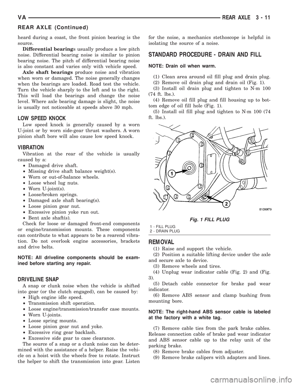
STANDARD PROCEDURE - DRAIN AND FILL
NOTE: Drain oil when warm.
(1) Clean area around oil fill plug and drain plug.
(2) Remove oil drain plug and drain oil (Fig. 1).
(3) Install oil drain plug and tighten to N´m 100
(74 ft. lbs.).
(4) Remove oil fill plug and fill housing up to bot-
tom edge of oil fill hole (Fig. 1).
(5) Install oil fill plug and tighten to N´m 100 (74
ft. lbs.).
REMOVAL
(1) Raise and support the vehicle.
(2) Position a suitable lifting device under the axle
and secure axle to device.
(3) Remove wheels and tires.
(4) Unplug wear indicator cable (Fig. 2) and (Fig.
3).
(5) Detach cable connector for brake pad wear
indicator.
(6) Remove ABS sensor and clamp bushing from
mounting bore.
NOTE: The right-hand ABS sensor cable is labeled
at the factory with a white tag.
(7) Remove cable ties from the park brake cables.
Release connection cable of brake pad wear indicator
and ABS sensor cable up to the relay unit of the
parking brake.
(8) Remove brake cables from adjuster.
(9) Remove brake calipers with adapters and lines.
Fig. 1 FILL PLUG
1 - FILL PLUG
2 - DRAIN PLUG
VAREAR AXLE 3 - 11
REAR AXLE (Continued)
Page 107 of 1232
Operate tester pump to apply 103.4 kPa (15 psi)
pressure to system. If hoses enlarge excessively or
bulges while testing, replace as necessary. Observe
gauge pointer and determine condition of cooling sys-
tem according to following criteria:
Holds Steady:If pointer remains steady for two
minutes, serious coolant leaks are not present in sys-
tem. However, there could be an internal leak that
does not appear with normal system test pressure. If
it is certain that coolant is being lost and leaks can-
not be detected, inspect for interior leakage or per-
form Internal Leakage Test.
Drops Slowly:Indicates a small leak or seepage
is occurring. Examine all connections for seepage or
slight leakage with a flashlight. Inspect radiator,
hoses, gasket edges and heater. Seal small leak holes
with a Sealer Lubricant (or equivalent). Repair leak
holes and inspect system again with pressure
applied.
Drops Quickly:Indicates that serious leakage is
occurring. Examine system for external leakage. If
leaks are not visible, inspect for internal leakage.
Large radiator leak holes should be repaired by a
reputable radiator repair shop.
INTERNAL LEAKAGE INSPECTION
Remove engine oil pan drain plug and drain a
small amount of engine oil. If coolant is present in
the pan, it will drain first because it is heavier than
oil. An alternative method is to operate engine for a
short period to churn the oil. After this is done,
remove engine dipstick and inspect for water glob-
ules. Also inspect transmission dipstick for water
globules and transmission fluid cooler for leakage.
WARNING: WITH RADIATOR PRESSURE TESTER
TOOL INSTALLED ON RADIATOR, DO NOT ALLOW
PRESSURE TO EXCEED 110 KPA (20 PSI). PRES-
SURE WILL BUILD UP QUICKLY IF A COMBUSTION
LEAK IS PRESENT. TO RELEASE PRESSURE,
ROCK TESTER FROM SIDE TO SIDE. WHEN
REMOVING TESTER, DO NOT TURN TESTER MORE
THAN 1/2 TURN IF SYSTEM IS UNDER PRESSURE.
Operate engine without pressure cap on coolant
container until thermostat opens. Attach a Pressure
Tester to container. If pressure builds up quickly it
indicates a combustion leak exists. This is usually
the result of a cylinder head gasket leak or crack in
engine. Repair as necessary.
If there is not an immediate pressure increase,
pump the Pressure Tester. Do this until indicated
pressure is within system range of 110 kPa (16 psi).
Fluctuation of gauge pointer indicates compression or
combustion leakage into cooling system.Because the vehicle is equipped with a catalytic
converter,do notremove spark plug cables or short
out cylinders to isolate compression leak.
If the needle on dial of pressure tester does not
fluctuate, race engine a few times to check for an
abnormal amount of coolant or steam. This would be
emitting from exhaust pipe. Coolant or steam from
exhaust pipe may indicate a faulty cylinder head gas-
ket, cracked engine cylinder block or cylinder head.
A convenient check for exhaust gas leakage into
cooling system is provided by a commercially avail-
able Block Leak Check tool. Follow manufacturers
instructions when using this product.
COMBUSTION LEAKAGE TEST - WITHOUT
PRESSURE TESTER
DO NOT WASTE reusable coolant. If solution is
clean, drain coolant into a clean and suitably marked
container for reuse.
WARNING: DO NOT REMOVE CYLINDER BLOCK
DRAIN PLUGS OR LOOSEN RADIATOR DRAIN
WITH SYSTEM HOT AND UNDER PRESSURE. SERI-
OUS BURNS FROM COOLANT CAN OCCUR.
Drain sufficient coolant to allow thermostat removal.
Remove accessory drive belt.
Add coolant to pressure container to bring level to
within 6.3 mm (1/4 in) of top of thermostat housing.
CAUTION: Avoid overheating. Do not operate
engine for an excessive period of time. Open drain-
cock immediately after test to eliminate boil over.
Start engine and accelerate rapidly three times, to
approximately 3000 rpm while observing coolant. If
internal engine combustion gases are leaking into
cooling system, bubbles will appear in coolant. If bub-
bles do not appear, internal combustion gas leakage
is not present.
STANDARD PROCEDURE
STANDARD PROCEDURE - ADDING
ADDITIONAL COOLANT
The use of aluminum cylinder blocks, cylinder
heads and water pumps requires special corrosion
protection. Only MopartAntifreeze/Coolant, 5
Year/100,000 Mile Formula (glycol base coolant with
corrosion inhibitors called HOAT, for Hybrid Organic
Additive Technology) is recommended. This coolant
offers the best engine cooling without corrosion when
mixed with 50% distilled water to obtain to obtain a
freeze point of -37ÉC (-35ÉF). If it loses color or
becomes contaminated, drain, flush, and replace with
fresh properly mixed coolant solution.
VAENGINE 7 - 11
COOLANT (Continued)
Page 114 of 1232
(16) Install A/C condenser.
(17) Install front bumper.
(18) Install front end cross member.
(19) Refill power steering to proper level.
(20) Refill transmission to proper level.
(21) Close radiator drain plug and refill the cooling
system to the correct level with the appropriate cool-
ant mixture.
(22) Recharge air conditioning.
(23) Run engine until warm and check for leaks.
RADIATOR PRESSURE CAP
DESCRIPTION
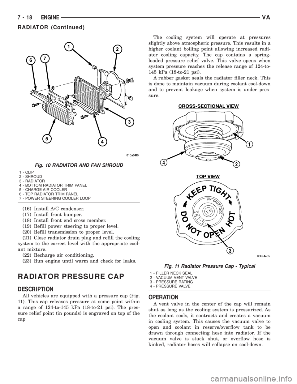
All vehicles are equipped with a pressure cap (Fig.
11). This cap releases pressure at some point within
a range of 124-to-145 kPa (18-to-21 psi). The pres-
sure relief point (in pounds) is engraved on top of the
capThe cooling system will operate at pressures
slightly above atmospheric pressure. This results in a
higher coolant boiling point allowing increased radi-
ator cooling capacity. The cap contains a spring-
loaded pressure relief valve. This valve opens when
system pressure reaches the release range of 124-to-
145 kPa (18-to-21 psi).
A rubber gasket seals the radiator filler neck. This
is done to maintain vacuum during coolant cool-down
and to prevent leakage when system is under pres-
sure.OPERATION
A vent valve in the center of the cap will remain
shut as long as the cooling system is pressurized. As
the coolant cools, it contracts and creates a vacuum
in cooling system. This causes the vacuum valve to
open and coolant in reserve/overflow tank to be
drawn through connecting hose into radiator. If the
vacuum valve is stuck shut, or overflow hose is
kinked, radiator hoses will collapse on cool-down.
Fig. 10 RADIATOR AND FAN SHROUD
1 - CLIP
2 - SHROUD
3 - RADIATOR
4 - BOTTOM RADIATOR TRIM PANEL
5 - CHARGE AIR COOLER
6 - TOP RADIATOR TRIM PANEL
7 - POWER STEERING COOLER LOOP
Fig. 11 Radiator Pressure Cap - Typical
1 - FILLER NECK SEAL
2 - VACUUM VENT VALVE
3 - PRESSURE RATING
4 - PRESSURE VALVE
7 - 18 ENGINEVA
RADIATOR (Continued)
Page 747 of 1232
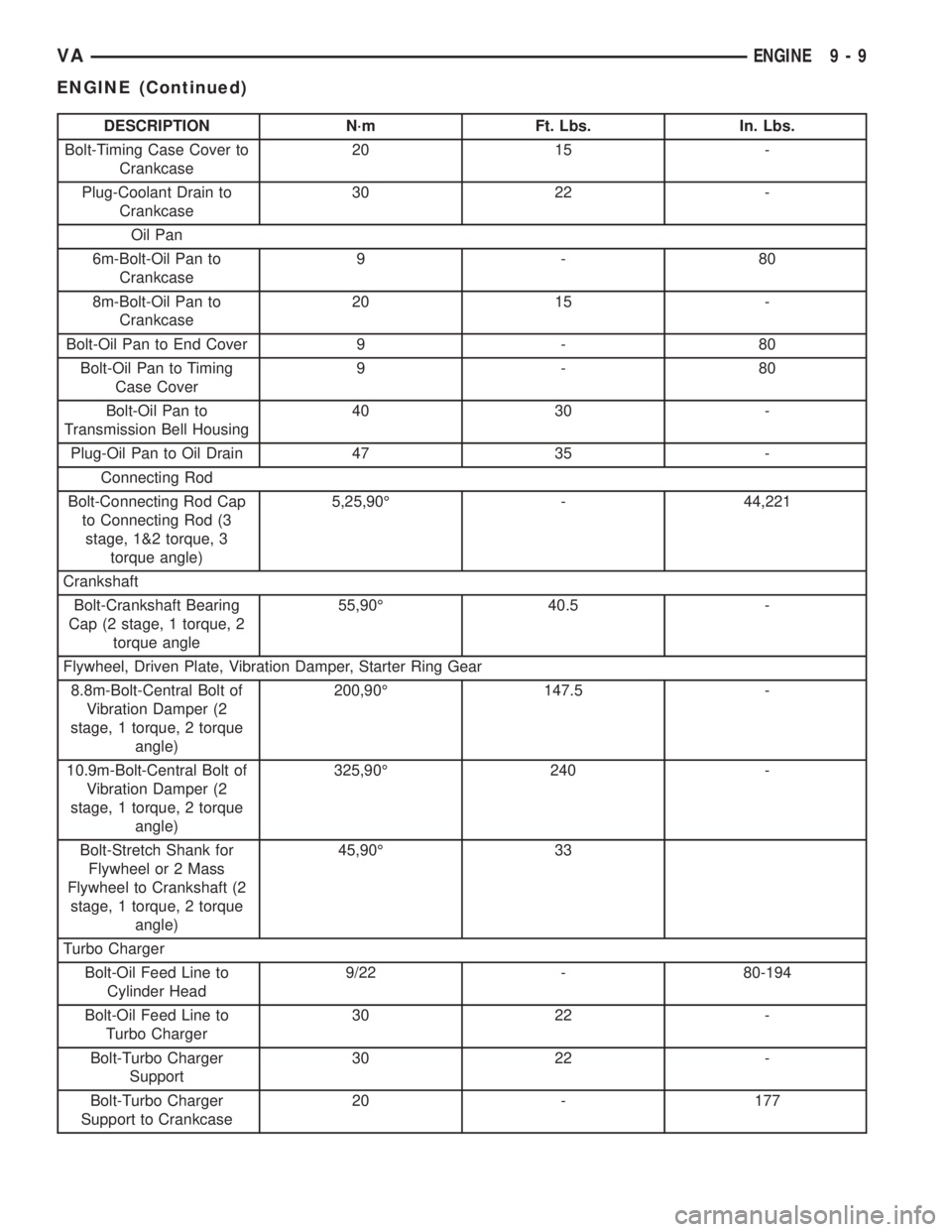
DESCRIPTION N´m Ft. Lbs. In. Lbs.
Bolt-Timing Case Cover to
Crankcase20 15 -
Plug-Coolant Drain to
Crankcase30 22 -
Oil Pan
6m-Bolt-Oil Pan to
Crankcase9-80
8m-Bolt-Oil Pan to
Crankcase20 15 -
Bolt-Oil Pan to End Cover 9 - 80
Bolt-Oil Pan to Timing
Case Cover9-80
Bolt-Oil Pan to
Transmission Bell Housing40 30 -
Plug-Oil Pan to Oil Drain 47 35 -
Connecting Rod
Bolt-Connecting Rod Cap
to Connecting Rod (3
stage, 1&2 torque, 3
torque angle)5,25,90É - 44,221
Crankshaft
Bolt-Crankshaft Bearing
Cap (2 stage, 1 torque, 2
torque angle55,90É 40.5 -
Flywheel, Driven Plate, Vibration Damper, Starter Ring Gear
8.8m-Bolt-Central Bolt of
Vibration Damper (2
stage, 1 torque, 2 torque
angle)200,90É 147.5 -
10.9m-Bolt-Central Bolt of
Vibration Damper (2
stage, 1 torque, 2 torque
angle)325,90É 240 -
Bolt-Stretch Shank for
Flywheel or 2 Mass
Flywheel to Crankshaft (2
stage, 1 torque, 2 torque
angle)45,90É 33
Turbo Charger
Bolt-Oil Feed Line to
Cylinder Head9/22 - 80-194
Bolt-Oil Feed Line to
Turbo Charger30 22 -
Bolt-Turbo Charger
Support30 22 -
Bolt-Turbo Charger
Support to Crankcase20 - 177
VAENGINE 9 - 9
ENGINE (Continued)
Page 902 of 1232
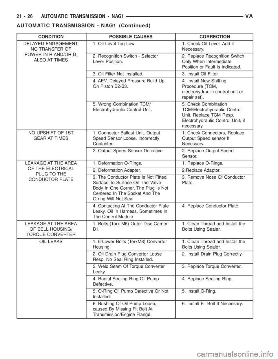
CONDITION POSSIBLE CAUSES CORRECTION
DELAYED ENGAGEMENT,
NO TRANSFER OF
POWER IN R AND/OR D,
ALSO AT TIMES1. Oil Level Too Low. 1. Check Oil Level. Add if
Necessary.
2. Recognition Switch - Selector
Lever Position.2. Replace Recognition Switch
Only When Intermediate
Position or Fault is Indicated.
3. Oil Filter Not Installed. 3. Install Oil Filter.
4. AEV, Delayed Pressure Build Up
On Piston B2/B3.4. Install New Shifting
Procedure (TCM,
electrohydraulic control unit or
repair set).
5. Wrong Combination TCM/
Electrohydraulic Control Unit.5. Check Combination
TCM/Electrohydraulic Control
Unit. Replace TCM Resp.
Electrohydraulic Control Unit, if
necessary.
NO UPSHIFT OF 1ST
GEAR AT TIMES1. Connector Ballast Unit. Output
Speed Sensor Loose, Incorrectly
Contacted.1. Check Connectors, Replace
Output Speed sensor If
Necessary.
2. Output Speed Sensor Defective 2. Replace Output Speed
Sensor.
LEAKAGE AT THE AREA
OF THE ELECTRICAL
PLUG TO THE
CONDUCTOR PLATE1. Deformation O-Rings. 1. Replace O-Rings.
2. Deformation Adapter. 2.Replace Adaptor.
3. The Conductor Plate Is Not Fitted
Surface To Surface On The Valve
Body In One Corner, The Plug Is Not
Centered In The Socket And The
O-ring Will Not Seal.3. Remove Nose Of Conductor
Plate.
4. Contacting At The Conductor Plate
Leaky. Oil In Harness, Sometimes In
The Control Module.4. Replace Conductor Plate.
LEAKAGE AT THE AREA
OF BELL HOUSING/
TORQUE CONVERTER1. Bolts (Torx M6) Outer Disc Carrier
B1.1. Clean Thread and Install the
Bolts Using Sealer.
OIL LEAKS 1. 6 Lower Bolts (TorxM8) Converter
Housing.1. Clean Thread and Install the
Bolts Using Sealer.
2. Oil Drain Plug Converter Loose
Resp. No Seal Ring Installed.2. Install Drain Plug Correctly.
3. Weld Seam Of Torque Converter
Leaky.3. Replace Torque Converter.
4. Radial Sealing Ring Oil Pump
Defective.4. Replace Sealing Ring.
5. O-Ring Oil Pump Defective Or Not
Installed.5. Install O-Ring.
6. Bushing Of Oil Pump Loose,
caused By Missing Fit Bolt At
Transmission/Engine Flange.6. Install Fit Bolt If Necessary.
21 - 26 AUTOMATIC TRANSMISSION - NAG1VA
AUTOMATIC TRANSMISSION - NAG1 (Continued)
Page 903 of 1232
STANDARD PROCEDURE - ALUMINUM
THREAD REPAIR
Damaged or worn threads in the aluminum trans-
mission case and valve body can be repaired by the
use of Heli-CoilsŸ, or equivalent. This repair con-
sists of drilling out the worn-out damaged threads.
Then tap the hole with a special Heli-CoilŸ tap, or
equivalent, and installing a Heli-CoilŸ insert, or
equivalent, into the hole. This brings the hole back to
its original thread size.
Heli-CoilŸ, or equivalent, tools and inserts are
readily available from most automotive parts suppli-
ers.
REMOVAL
(1) Disconnect the negative (ground) battery cable.
CAUTION: Isolate ground lead to prevent accidental
contact.
(2) Apply parking brake.
(3) Move gear selector lever to position9N9.
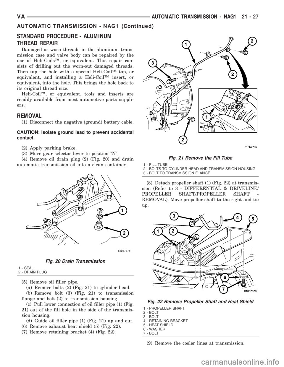
(4) Remove oil drain plug (2) (Fig. 20) and drain
automatic transmission oil into a clean container.
(5) Remove oil filler pipe.
(a) Remove bolts (2) (Fig. 21) to cylinder head.
(b) Remove bolt (3) (Fig. 21) to transmission
flange and bolt (2) to transmission housing.
(c) Pull lower connection of oil filler pipe (1) (Fig.
21) out of the fill hole in the side of the transmis-
sion housing.
(d) Guide oil filler pipe (1) (Fig. 21) up and out.
(6) Remove exhaust heat shield (5) (Fig. 22).
(7) Remove retaining bracket (4) (Fig. 22).(8) Detach propeller shaft (1) (Fig. 22) at transmis-
sion (Refer to 3 - DIFFERENTIAL & DRIVELINE/
PROPELLER SHAFT/PROPELLER SHAFT -
REMOVAL). Move propeller shaft to the right and tie
up.
(9) Remove the cooler lines at transmission.
Fig. 20 Drain Transmission
1 - SEAL
2 - DRAIN PLUG
Fig. 21 Remove the Fill Tube
1 - FILL TUBE
2 - BOLTS TO CYLINDER HEAD AND TRANSMISSION HOUSING
3 - BOLT TO TRANSMISSION FLANGE
Fig. 22 Remove Propeller Shaft and Heat Shield
1 - PROPELLER SHAFT
2 - BOLT
3 - BOLT
4 - RETAINING BRACKET
5 - HEAT SHIELD
6 - WASHER
7 - BOLT
VAAUTOMATIC TRANSMISSION - NAG1 21 - 27
AUTOMATIC TRANSMISSION - NAG1 (Continued)
Page 907 of 1232
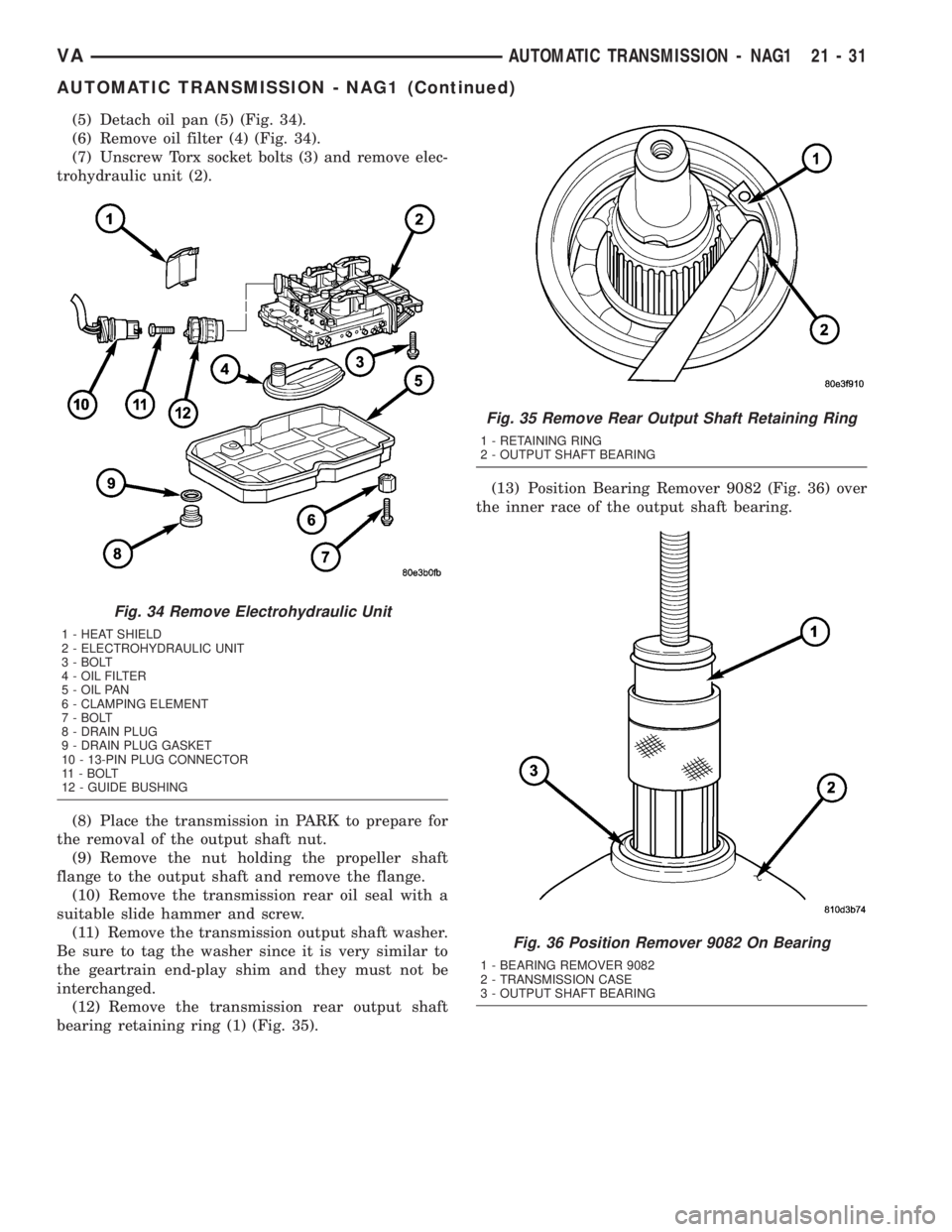
(5) Detach oil pan (5) (Fig. 34).
(6) Remove oil filter (4) (Fig. 34).
(7) Unscrew Torx socket bolts (3) and remove elec-
trohydraulic unit (2).
(8) Place the transmission in PARK to prepare for
the removal of the output shaft nut.
(9) Remove the nut holding the propeller shaft
flange to the output shaft and remove the flange.
(10) Remove the transmission rear oil seal with a
suitable slide hammer and screw.
(11) Remove the transmission output shaft washer.
Be sure to tag the washer since it is very similar to
the geartrain end-play shim and they must not be
interchanged.
(12) Remove the transmission rear output shaft
bearing retaining ring (1) (Fig. 35).(13) Position Bearing Remover 9082 (Fig. 36) over
the inner race of the output shaft bearing.
Fig. 34 Remove Electrohydraulic Unit
1 - HEAT SHIELD
2 - ELECTROHYDRAULIC UNIT
3 - BOLT
4 - OIL FILTER
5 - OIL PAN
6 - CLAMPING ELEMENT
7 - BOLT
8 - DRAIN PLUG
9 - DRAIN PLUG GASKET
10 - 13-PIN PLUG CONNECTOR
11 - BOLT
12 - GUIDE BUSHING
Fig. 35 Remove Rear Output Shaft Retaining Ring
1 - RETAINING RING
2 - OUTPUT SHAFT BEARING
Fig. 36 Position Remover 9082 On Bearing
1 - BEARING REMOVER 9082
2 - TRANSMISSION CASE
3 - OUTPUT SHAFT BEARING
VAAUTOMATIC TRANSMISSION - NAG1 21 - 31
AUTOMATIC TRANSMISSION - NAG1 (Continued)
Page 917 of 1232
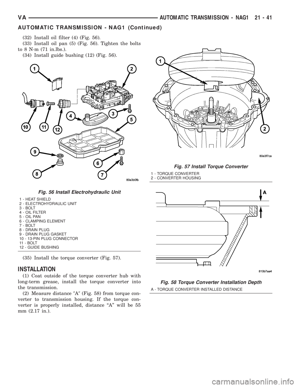
(32) Install oil filter (4) (Fig. 56).
(33) Install oil pan (5) (Fig. 56). Tighten the bolts
to 8 N´m (71 in.lbs.).
(34) Install guide bushing (12) (Fig. 56).
(35) Install the torque converter (Fig. 57).
INSTALLATION
(1) Coat outside of the torque converter hub with
long-term grease, install the torque converter into
the transmission.
(2) Measure distance9A9(Fig. 58) from torque con-
verter to transmission housing. If the torque con-
verter is properly installed, distance ªAº will be 55
mm (2.17 in.).
Fig. 56 Install Electrohydraulic Unit
1 - HEAT SHIELD
2 - ELECTROHYDRAULIC UNIT
3 - BOLT
4 - OIL FILTER
5 - OIL PAN
6 - CLAMPING ELEMENT
7 - BOLT
8 - DRAIN PLUG
9 - DRAIN PLUG GASKET
10 - 13-PIN PLUG CONNECTOR
11 - BOLT
12 - GUIDE BUSHING
Fig. 57 Install Torque Converter
1 - TORQUE CONVERTER
2 - CONVERTER HOUSING
Fig. 58 Torque Converter Installation Depth
A - TORQUE CONVERTER INSTALLED DISTANCE
VAAUTOMATIC TRANSMISSION - NAG1 21 - 41
AUTOMATIC TRANSMISSION - NAG1 (Continued)
Page 922 of 1232
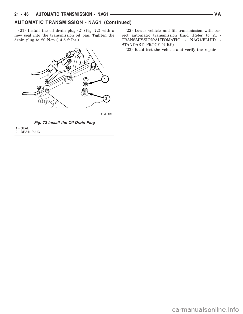
(21) Install the oil drain plug (2) (Fig. 72) with a
new seal into the transmission oil pan. Tighten the
drain plug to 20 N´m (14.5 ft.lbs.).(22) Lower vehicle and fill transmission with cor-
rect automatic transmission fluid (Refer to 21 -
TRANSMISSION/AUTOMATIC - NAG1/FLUID -
STANDARD PROCEDURE).
(23) Road test the vehicle and verify the repair.
Fig. 72 Install the Oil Drain Plug
1 - SEAL
2 - DRAIN PLUG
21 - 46 AUTOMATIC TRANSMISSION - NAG1VA
AUTOMATIC TRANSMISSION - NAG1 (Continued)