MERCEDES-BENZ SPRINTER 2006 Service Manual
Manufacturer: MERCEDES-BENZ, Model Year: 2006, Model line: SPRINTER, Model: MERCEDES-BENZ SPRINTER 2006Pages: 2305, PDF Size: 48.12 MB
Page 191 of 2305
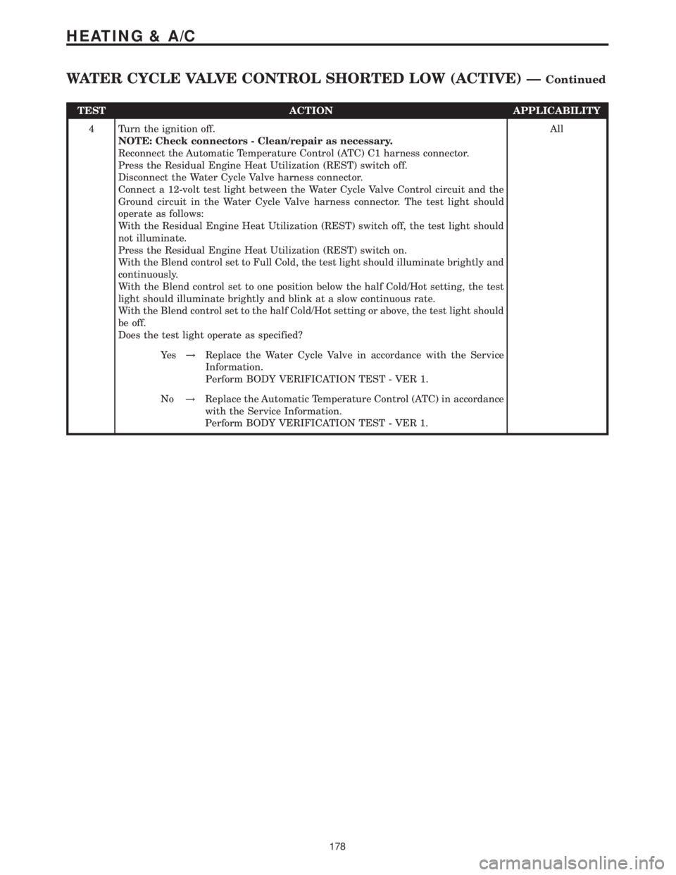
TEST ACTION APPLICABILITY
4 Turn the ignition off.
NOTE: Check connectors - Clean/repair as necessary.
Reconnect the Automatic Temperature Control (ATC) C1 harness connector.
Press the Residual Engine Heat Utilization (REST) switch off.
Disconnect the Water Cycle Valve harness connector.
Connect a 12-volt test light between the Water Cycle Valve Control circuit and the
Ground circuit in the Water Cycle Valve harness connector. The test light should
operate as follows:
With the Residual Engine Heat Utilization (REST) switch off, the test light should
not illuminate.
Press the Residual Engine Heat Utilization (REST) switch on.
With the Blend control set to Full Cold, the test light should illuminate brightly and
continuously.
With the Blend control set to one position below the half Cold/Hot setting, the test
light should illuminate brightly and blink at a slow continuous rate.
With the Blend control set to the half Cold/Hot setting or above, the test light should
be off.
Does the test light operate as specified?All
Ye s!Replace the Water Cycle Valve in accordance with the Service
Information.
Perform BODY VERIFICATION TEST - VER 1.
No!Replace the Automatic Temperature Control (ATC) in accordance
with the Service Information.
Perform BODY VERIFICATION TEST - VER 1.
178
HEATING & A/C
WATER CYCLE VALVE CONTROL SHORTED LOW (ACTIVE) ÐContinued
Page 192 of 2305
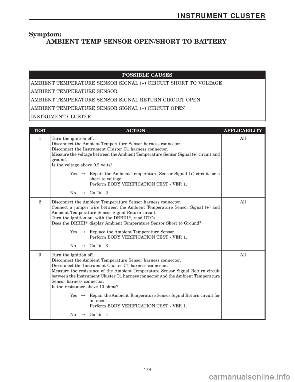
Symptom:
AMBIENT TEMP SENSOR OPEN/SHORT TO BATTERY
POSSIBLE CAUSES
AMBIENT TEMPERATURE SENSOR SIGNAL (+) CIRCUIT SHORT TO VOLTAGE
AMBIENT TEMPERATURE SENSOR
AMBIENT TEMPERATURE SENSOR SIGNAL RETURN CIRCUIT OPEN
AMBIENT TEMPERATURE SENSOR SIGNAL (+) CIRCUIT OPEN
INSTRUMENT CLUSTER
TEST ACTION APPLICABILITY
1 Turn the ignition off.
Disconnect the Ambient Temperature Sensor harness connector.
Disconnect the Instrument Cluster C1 harness connector.
Measure the voltage between the Ambient Temperature Sensor Signal (+) circuit and
ground.
Is the voltage above 0.2 volts?All
Ye s!Repair the Ambient Temperature Sensor Signal (+) circuit for a
short to voltage.
Perform BODY VERIFICATION TEST - VER 1.
No!Go To 2
2 Disconnect the Ambient Temperature Sensor harness connector.
Connect a jumper wire between the Ambient Temperature Sensor Signal (+) and
Ambient Temperature Sensor Signal Return circuit.
Turn the ignition on, with the DRBIIIt, read DTCs.
Does the DRBIIItdisplay Ambient Temperature Sensor Short to Ground?All
Ye s!Replace the Ambient Temperature Sensor.
Perform BODY VERIFICATION TEST - VER 1.
No!Go To 3
3 Turn the ignition off.
Disconnect the Ambient Temperature Sensor harness connector.
Disconnect the Instrument Cluster C1 harness connector.
Measure the resistance of the Ambient Temperature Sensor Signal Return circuit
between the Instrument Cluster C1 harness connector and the Ambient Temperature
Sensor harness connector.
Is the resistance above 10 ohms?All
Ye s!Repair the Ambient Temperature Sensor Signal Return circuit for
an open.
Perform BODY VERIFICATION TEST - VER 1.
No!Go To 4
179
INSTRUMENT CLUSTER
Page 193 of 2305
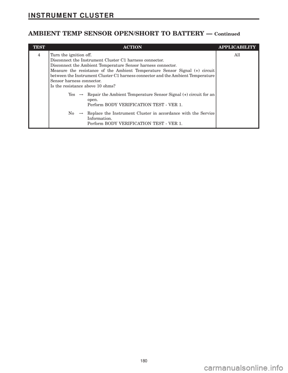
TEST ACTION APPLICABILITY
4 Turn the ignition off.
Disconnect the Instrument Cluster C1 harness connector.
Disconnect the Ambient Temperature Sensor harness connector.
Measure the resistance of the Ambient Temperature Sensor Signal (+) circuit
between the Instrument Cluster C1 harness connector and the Ambient Temperature
Sensor harness connector.
Is the resistance above 10 ohms?All
Ye s!Repair the Ambient Temperature Sensor Signal (+) circuit for an
open.
Perform BODY VERIFICATION TEST - VER 1.
No!Replace the Instrument Cluster in accordance with the Service
Information.
Perform BODY VERIFICATION TEST - VER 1.
180
INSTRUMENT CLUSTER
AMBIENT TEMP SENSOR OPEN/SHORT TO BATTERY ÐContinued
Page 194 of 2305
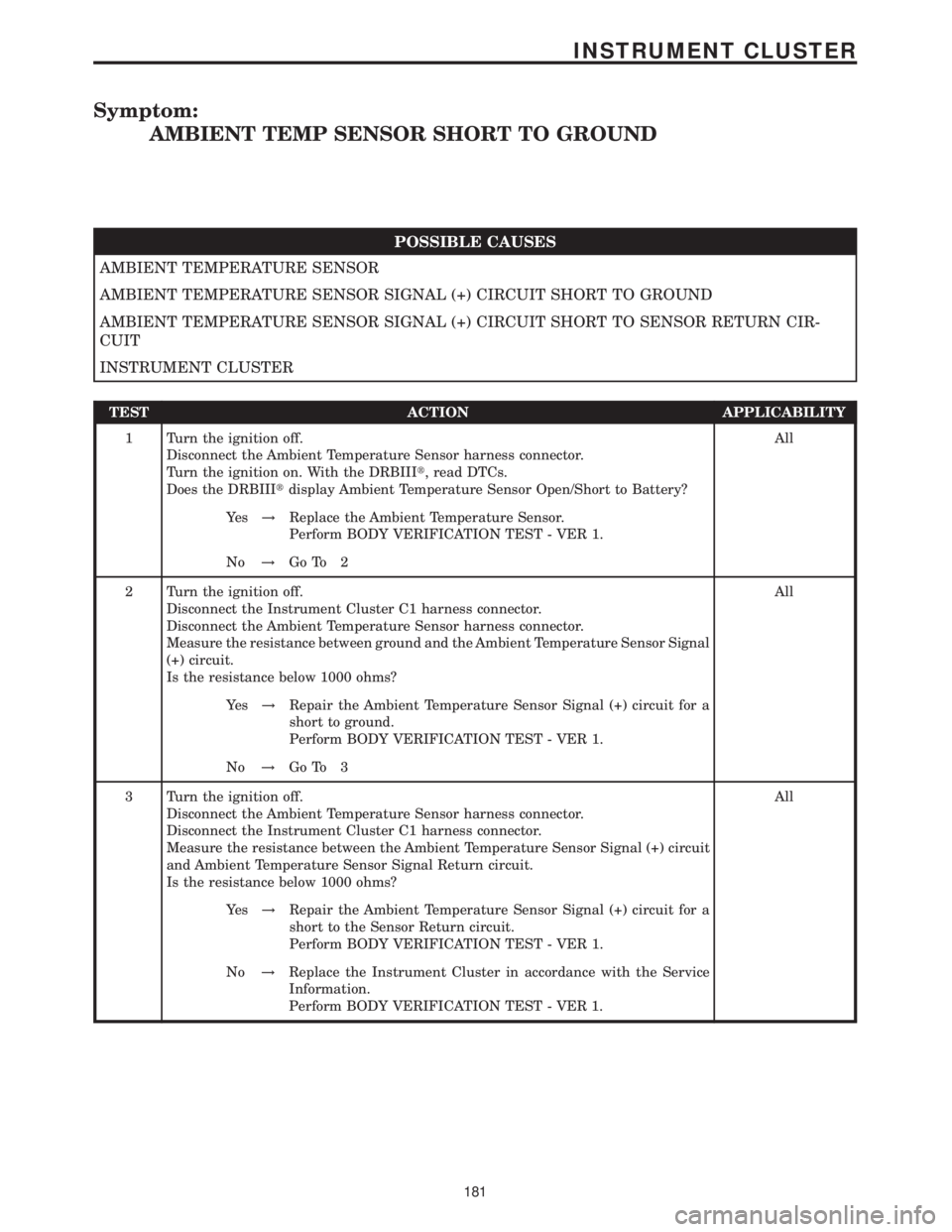
Symptom:
AMBIENT TEMP SENSOR SHORT TO GROUND
POSSIBLE CAUSES
AMBIENT TEMPERATURE SENSOR
AMBIENT TEMPERATURE SENSOR SIGNAL (+) CIRCUIT SHORT TO GROUND
AMBIENT TEMPERATURE SENSOR SIGNAL (+) CIRCUIT SHORT TO SENSOR RETURN CIR-
CUIT
INSTRUMENT CLUSTER
TEST ACTION APPLICABILITY
1 Turn the ignition off.
Disconnect the Ambient Temperature Sensor harness connector.
Turn the ignition on. With the DRBIIIt, read DTCs.
Does the DRBIIItdisplay Ambient Temperature Sensor Open/Short to Battery?All
Ye s!Replace the Ambient Temperature Sensor.
Perform BODY VERIFICATION TEST - VER 1.
No!Go To 2
2 Turn the ignition off.
Disconnect the Instrument Cluster C1 harness connector.
Disconnect the Ambient Temperature Sensor harness connector.
Measure the resistance between ground and the Ambient Temperature Sensor Signal
(+) circuit.
Is the resistance below 1000 ohms?All
Ye s!Repair the Ambient Temperature Sensor Signal (+) circuit for a
short to ground.
Perform BODY VERIFICATION TEST - VER 1.
No!Go To 3
3 Turn the ignition off.
Disconnect the Ambient Temperature Sensor harness connector.
Disconnect the Instrument Cluster C1 harness connector.
Measure the resistance between the Ambient Temperature Sensor Signal (+) circuit
and Ambient Temperature Sensor Signal Return circuit.
Is the resistance below 1000 ohms?All
Ye s!Repair the Ambient Temperature Sensor Signal (+) circuit for a
short to the Sensor Return circuit.
Perform BODY VERIFICATION TEST - VER 1.
No!Replace the Instrument Cluster in accordance with the Service
Information.
Perform BODY VERIFICATION TEST - VER 1.
181
INSTRUMENT CLUSTER
Page 195 of 2305
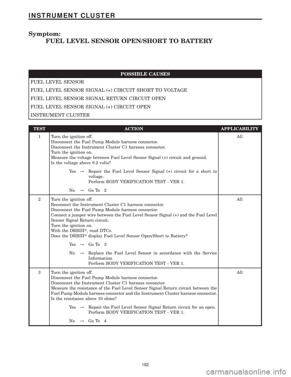
Symptom:
FUEL LEVEL SENSOR OPEN/SHORT TO BATTERY
POSSIBLE CAUSES
FUEL LEVEL SENSOR
FUEL LEVEL SENSOR SIGNAL (+) CIRCUIT SHORT TO VOLTAGE
FUEL LEVEL SENSOR SIGNAL RETURN CIRCUIT OPEN
FUEL LEVEL SENSOR SIGNAL (+) CIRCUIT OPEN
INSTRUMENT CLUSTER
TEST ACTION APPLICABILITY
1 Turn the ignition off.
Disconnect the Fuel Pump Module harness connector.
Disconnect the Instrument Cluster C1 harness connector.
Turn the ignition on.
Measure the voltage between Fuel Level Sensor Signal (+) circuit and ground.
Is the voltage above 0.2 volts?All
Ye s!Repair the Fuel Level Sensor Signal (+) circuit for a short to
voltage.
Perform BODY VERIFICATION TEST - VER 1.
No!Go To 2
2 Turn the ignition off.
Reconnect the Instrument Cluster C1 harness connector.
Disconnect the Fuel Pump Module harness connector.
Connect a jumper wire between the Fuel Level Sensor Signal (+) and the Fuel Level
Sensor Signal Return circuit.
Turn the ignition on.
With the DRBIIIt, read DTCs.
Does the DRBIIItdisplay Fuel Level Sensor Open/Short to Battery?All
Ye s!Go To 3
No!Replace the Fuel Level Sensor in accordance with the Service
Information.
Perform BODY VERIFICATION TEST - VER 1.
3 Turn the ignition off.
Disconnect the Fuel Pump Module harness connector.
Disconnect the Instrument Cluster C1 harness connector.
Measure the resistance of the Fuel Level Sensor Signal Return circuit between the
Fuel Pump Module harness connector and the Instrument Cluster harness connector.
Is the resistance above 10 ohms?All
Ye s!Repair the Fuel Level Sensor Signal Return circuit for an open.
Perform BODY VERIFICATION TEST - VER 1.
No!Go To 4
182
INSTRUMENT CLUSTER
Page 196 of 2305
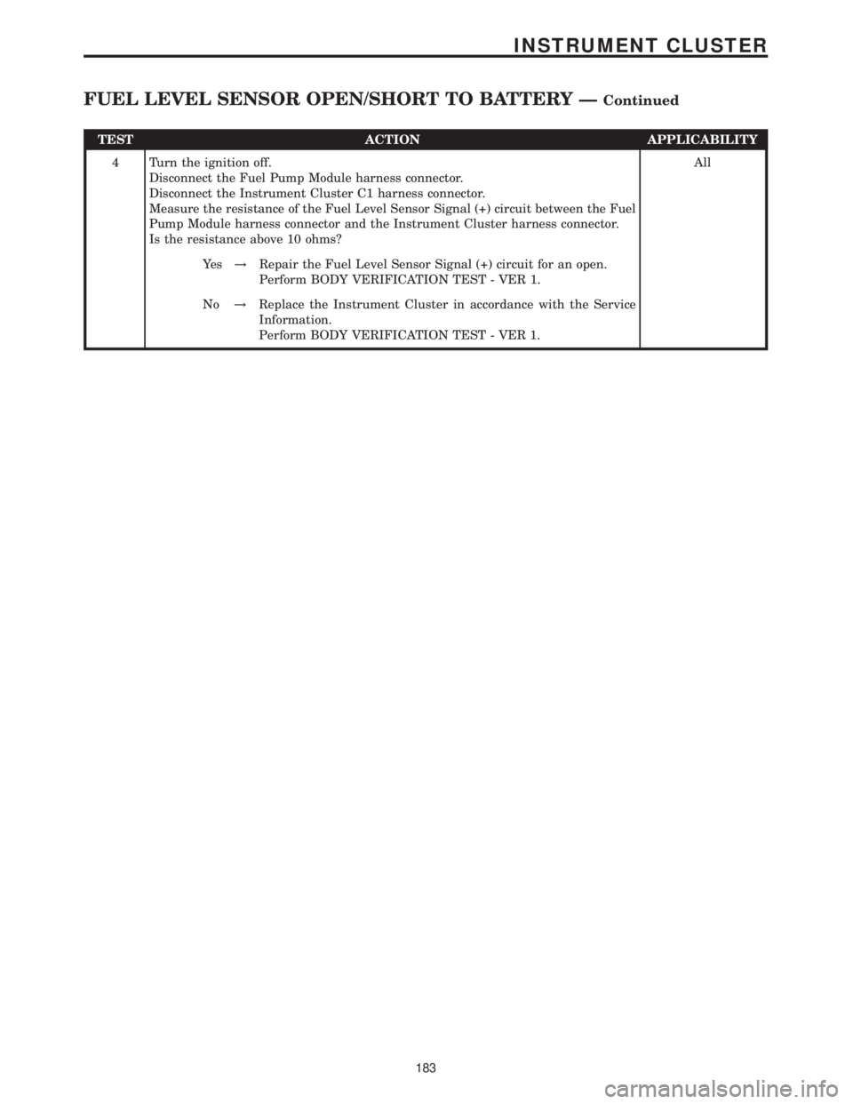
TEST ACTION APPLICABILITY
4 Turn the ignition off.
Disconnect the Fuel Pump Module harness connector.
Disconnect the Instrument Cluster C1 harness connector.
Measure the resistance of the Fuel Level Sensor Signal (+) circuit between the Fuel
Pump Module harness connector and the Instrument Cluster harness connector.
Is the resistance above 10 ohms?All
Ye s!Repair the Fuel Level Sensor Signal (+) circuit for an open.
Perform BODY VERIFICATION TEST - VER 1.
No!Replace the Instrument Cluster in accordance with the Service
Information.
Perform BODY VERIFICATION TEST - VER 1.
183
INSTRUMENT CLUSTER
FUEL LEVEL SENSOR OPEN/SHORT TO BATTERY ÐContinued
Page 197 of 2305
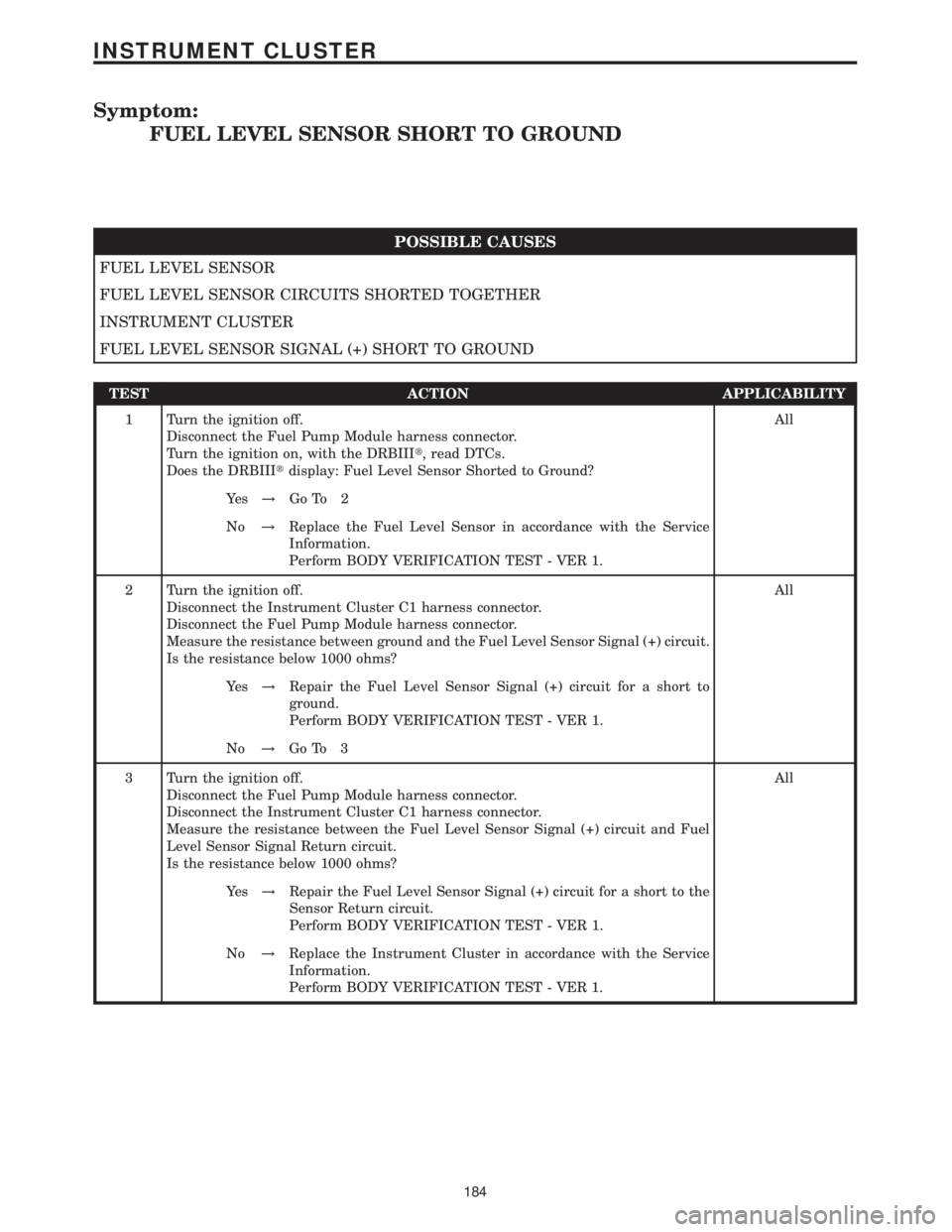
Symptom:
FUEL LEVEL SENSOR SHORT TO GROUND
POSSIBLE CAUSES
FUEL LEVEL SENSOR
FUEL LEVEL SENSOR CIRCUITS SHORTED TOGETHER
INSTRUMENT CLUSTER
FUEL LEVEL SENSOR SIGNAL (+) SHORT TO GROUND
TEST ACTION APPLICABILITY
1 Turn the ignition off.
Disconnect the Fuel Pump Module harness connector.
Turn the ignition on, with the DRBIIIt, read DTCs.
Does the DRBIIItdisplay: Fuel Level Sensor Shorted to Ground?All
Ye s!Go To 2
No!Replace the Fuel Level Sensor in accordance with the Service
Information.
Perform BODY VERIFICATION TEST - VER 1.
2 Turn the ignition off.
Disconnect the Instrument Cluster C1 harness connector.
Disconnect the Fuel Pump Module harness connector.
Measure the resistance between ground and the Fuel Level Sensor Signal (+) circuit.
Is the resistance below 1000 ohms?All
Ye s!Repair the Fuel Level Sensor Signal (+) circuit for a short to
ground.
Perform BODY VERIFICATION TEST - VER 1.
No!Go To 3
3 Turn the ignition off.
Disconnect the Fuel Pump Module harness connector.
Disconnect the Instrument Cluster C1 harness connector.
Measure the resistance between the Fuel Level Sensor Signal (+) circuit and Fuel
Level Sensor Signal Return circuit.
Is the resistance below 1000 ohms?All
Ye s!Repair the Fuel Level Sensor Signal (+) circuit for a short to the
Sensor Return circuit.
Perform BODY VERIFICATION TEST - VER 1.
No!Replace the Instrument Cluster in accordance with the Service
Information.
Perform BODY VERIFICATION TEST - VER 1.
184
INSTRUMENT CLUSTER
Page 198 of 2305
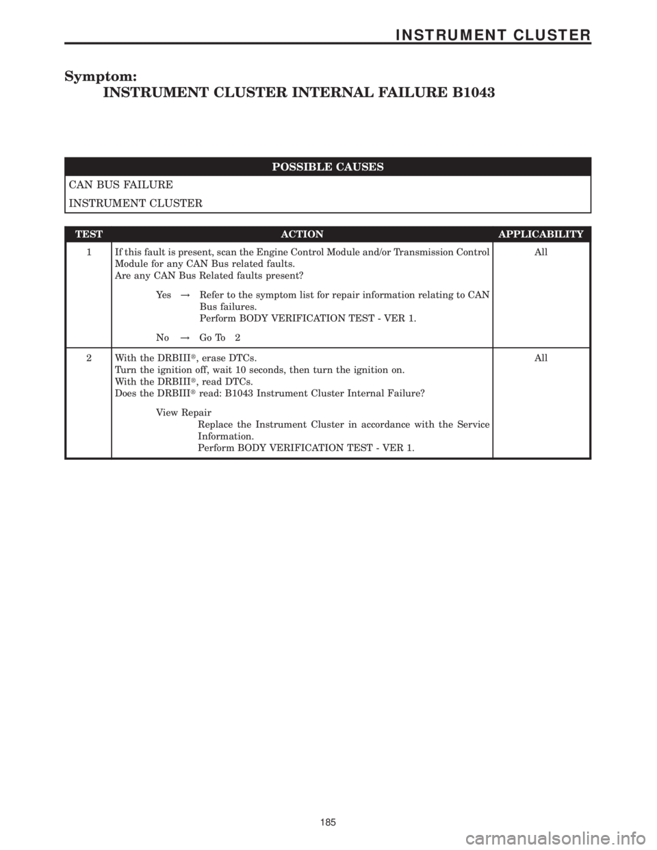
Symptom:
INSTRUMENT CLUSTER INTERNAL FAILURE B1043
POSSIBLE CAUSES
CAN BUS FAILURE
INSTRUMENT CLUSTER
TEST ACTION APPLICABILITY
1 If this fault is present, scan the Engine Control Module and/or Transmission Control
Module for any CAN Bus related faults.
Are any CAN Bus Related faults present?All
Ye s!Refer to the symptom list for repair information relating to CAN
Bus failures.
Perform BODY VERIFICATION TEST - VER 1.
No!Go To 2
2 With the DRBIIIt, erase DTCs.
Turn the ignition off, wait 10 seconds, then turn the ignition on.
With the DRBIIIt, read DTCs.
Does the DRBIIItread: B1043 Instrument Cluster Internal Failure?All
View Repair
Replace the Instrument Cluster in accordance with the Service
Information.
Perform BODY VERIFICATION TEST - VER 1.
185
INSTRUMENT CLUSTER
Page 199 of 2305
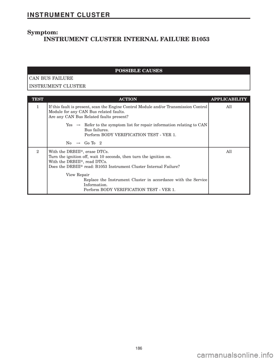
Symptom:
INSTRUMENT CLUSTER INTERNAL FAILURE B1053
POSSIBLE CAUSES
CAN BUS FAILURE
INSTRUMENT CLUSTER
TEST ACTION APPLICABILITY
1 If this fault is present, scan the Engine Control Module and/or Transmission Control
Module for any CAN Bus related faults.
Are any CAN Bus Related faults present?All
Ye s!Refer to the symptom list for repair information relating to CAN
Bus failures.
Perform BODY VERIFICATION TEST - VER 1.
No!Go To 2
2 With the DRBIIIt, erase DTCs.
Turn the ignition off, wait 10 seconds, then turn the ignition on.
With the DRBIIIt, read DTCs.
Does the DRBIIItread: B1053 Instrument Cluster Internal Failure?All
View Repair
Replace the Instrument Cluster in accordance with the Service
Information.
Perform BODY VERIFICATION TEST - VER 1.
186
INSTRUMENT CLUSTER
Page 200 of 2305
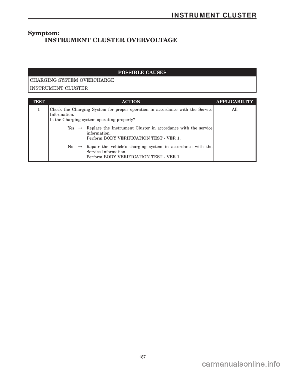
Symptom:
INSTRUMENT CLUSTER OVERVOLTAGE
POSSIBLE CAUSES
CHARGING SYSTEM OVERCHARGE
INSTRUMENT CLUSTER
TEST ACTION APPLICABILITY
1 Check the Charging System for proper operation in accordance with the Service
Information.
Is the Charging system operating properly?All
Ye s!Replace the Instrument Cluster in accordance with the service
information.
Perform BODY VERIFICATION TEST - VER 1.
No!Repair the vehicle's charging system in accordance with the
Service Information.
Perform BODY VERIFICATION TEST - VER 1.
187
INSTRUMENT CLUSTER