MERCEDES-BENZ SPRINTER 2006 Service Manual
Manufacturer: MERCEDES-BENZ, Model Year: 2006, Model line: SPRINTER, Model: MERCEDES-BENZ SPRINTER 2006Pages: 2305, PDF Size: 48.12 MB
Page 221 of 2305
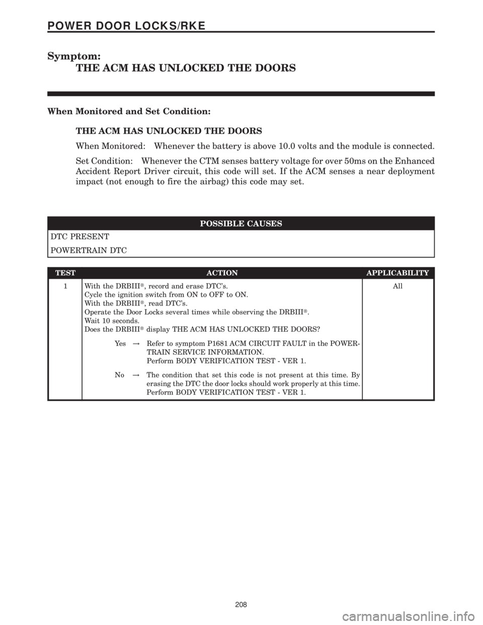
Symptom:
THE ACM HAS UNLOCKED THE DOORS
When Monitored and Set Condition:
THE ACM HAS UNLOCKED THE DOORS
When Monitored: Whenever the battery is above 10.0 volts and the module is connected.
Set Condition: Whenever the CTM senses battery voltage for over 50ms on the Enhanced
Accident Report Driver circuit, this code will set. If the ACM senses a near deployment
impact (not enough to fire the airbag) this code may set.
POSSIBLE CAUSES
DTC PRESENT
POWERTRAIN DTC
TEST ACTION APPLICABILITY
1 With the DRBIIIt, record and erase DTC's.
Cycle the ignition switch from ON to OFF to ON.
With the DRBIIIt, read DTC's.
Operate the Door Locks several times while observing the DRBIIIt.
Wait 10 seconds.
Does the DRBIIItdisplay THE ACM HAS UNLOCKED THE DOORS?All
Ye s!Refer to symptom P1681 ACM CIRCUIT FAULT in the POWER-
TRAIN SERVICE INFORMATION.
Perform BODY VERIFICATION TEST - VER 1.
No!The condition that set this code is not present at this time. By
erasing the DTC the door locks should work properly at this time.
Perform BODY VERIFICATION TEST - VER 1.
208
POWER DOOR LOCKS/RKE
Page 222 of 2305
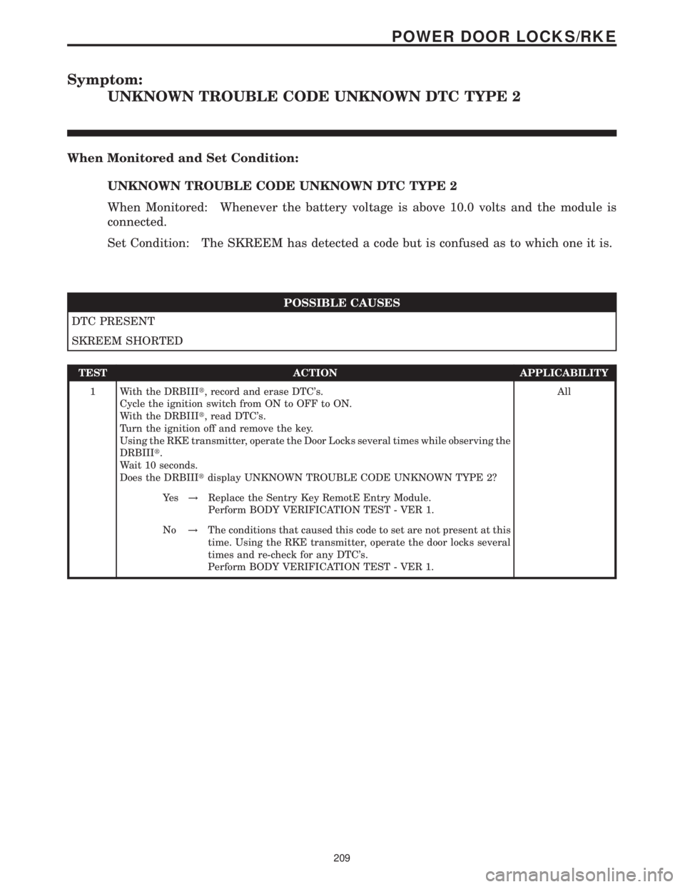
Symptom:
UNKNOWN TROUBLE CODE UNKNOWN DTC TYPE 2
When Monitored and Set Condition:
UNKNOWN TROUBLE CODE UNKNOWN DTC TYPE 2
When Monitored: Whenever the battery voltage is above 10.0 volts and the module is
connected.
Set Condition: The SKREEM has detected a code but is confused as to which one it is.
POSSIBLE CAUSES
DTC PRESENT
SKREEM SHORTED
TEST ACTION APPLICABILITY
1 With the DRBIIIt, record and erase DTC's.
Cycle the ignition switch from ON to OFF to ON.
With the DRBIIIt, read DTC's.
Turn the ignition off and remove the key.
Using the RKE transmitter, operate the Door Locks several times while observing the
DRBIIIt.
Wait 10 seconds.
Does the DRBIIItdisplay UNKNOWN TROUBLE CODE UNKNOWN TYPE 2?All
Ye s!Replace the Sentry Key RemotE Entry Module.
Perform BODY VERIFICATION TEST - VER 1.
No!The conditions that caused this code to set are not present at this
time. Using the RKE transmitter, operate the door locks several
times and re-check for any DTC's.
Perform BODY VERIFICATION TEST - VER 1.
209
POWER DOOR LOCKS/RKE
Page 223 of 2305
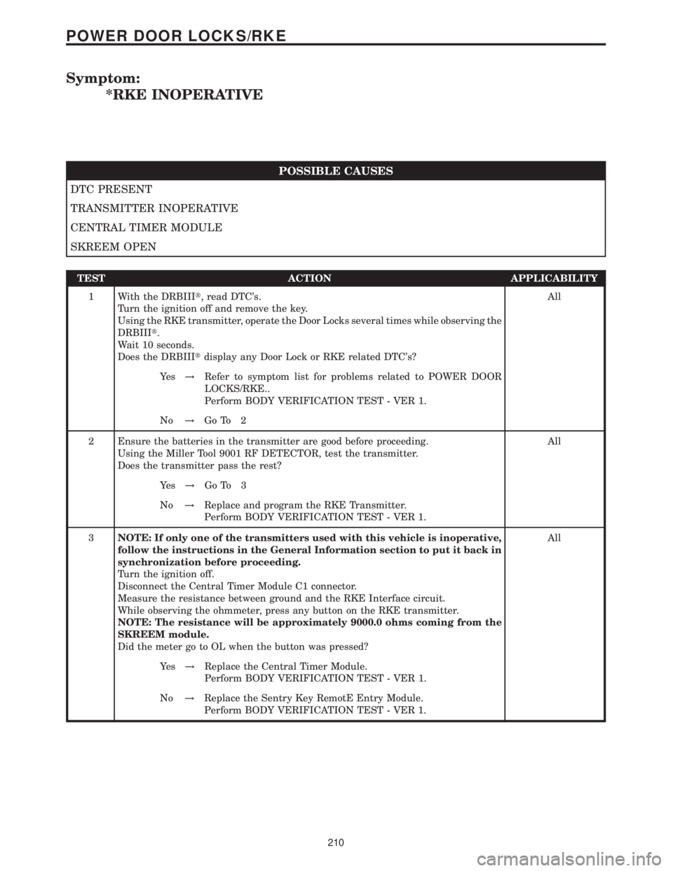
Symptom:
*RKE INOPERATIVE
POSSIBLE CAUSES
DTC PRESENT
TRANSMITTER INOPERATIVE
CENTRAL TIMER MODULE
SKREEM OPEN
TEST ACTION APPLICABILITY
1 With the DRBIIIt, read DTC's.
Turn the ignition off and remove the key.
Using the RKE transmitter, operate the Door Locks several times while observing the
DRBIIIt.
Wait 10 seconds.
Does the DRBIIItdisplay any Door Lock or RKE related DTC's?All
Ye s!Refer to symptom list for problems related to POWER DOOR
LOCKS/RKE..
Perform BODY VERIFICATION TEST - VER 1.
No!Go To 2
2 Ensure the batteries in the transmitter are good before proceeding.
Using the Miller Tool 9001 RF DETECTOR, test the transmitter.
Does the transmitter pass the rest?All
Ye s!Go To 3
No!Replace and program the RKE Transmitter.
Perform BODY VERIFICATION TEST - VER 1.
3NOTE: If only one of the transmitters used with this vehicle is inoperative,
follow the instructions in the General Information section to put it back in
synchronization before proceeding.
Turn the ignition off.
Disconnect the Central Timer Module C1 connector.
Measure the resistance between ground and the RKE Interface circuit.
While observing the ohmmeter, press any button on the RKE transmitter.
NOTE: The resistance will be approximately 9000.0 ohms coming from the
SKREEM module.
Did the meter go to OL when the button was pressed?All
Ye s!Replace the Central Timer Module.
Perform BODY VERIFICATION TEST - VER 1.
No!Replace the Sentry Key RemotE Entry Module.
Perform BODY VERIFICATION TEST - VER 1.
210
POWER DOOR LOCKS/RKE
Page 224 of 2305
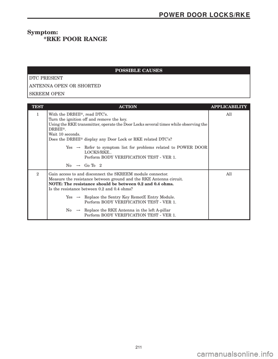
Symptom:
*RKE POOR RANGE
POSSIBLE CAUSES
DTC PRESENT
ANTENNA OPEN OR SHORTED
SKREEM OPEN
TEST ACTION APPLICABILITY
1 With the DRBIIIt, read DTC's.
Turn the ignition off and remove the key.
Using the RKE transmitter, operate the Door Locks several times while observing the
DRBIIIt.
Wait 10 seconds.
Does the DRBIIItdisplay any Door Lock or RKE related DTC's?All
Ye s!Refer to symptom list for problems related to POWER DOOR
LOCKS/RKE..
Perform BODY VERIFICATION TEST - VER 1.
No!Go To 2
2 Gain access to and disconnect the SKREEM module connector.
Measure the resistance between ground and the RKE Antenna circuit.
NOTE: The resistance should be between 0.2 and 0.4 ohms.
Is the resistance between 0.2 and 0.4 ohms?All
Ye s!Replace the Sentry Key RemotE Entry Module.
Perform BODY VERIFICATION TEST - VER 1.
No!Replace the RKE Antenna in the left A-pillar
Perform BODY VERIFICATION TEST - VER 1.
211
POWER DOOR LOCKS/RKE
Page 225 of 2305
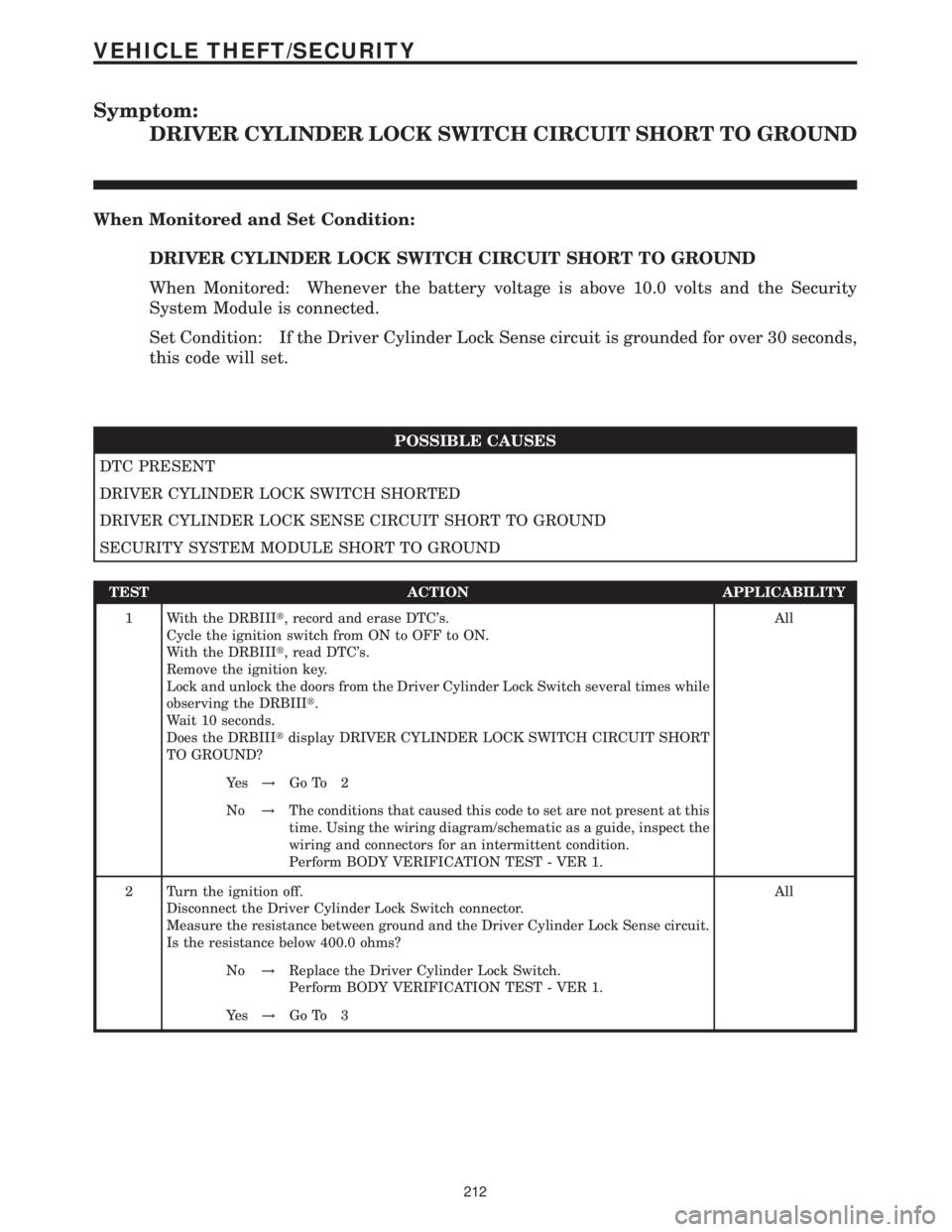
Symptom:
DRIVER CYLINDER LOCK SWITCH CIRCUIT SHORT TO GROUND
When Monitored and Set Condition:
DRIVER CYLINDER LOCK SWITCH CIRCUIT SHORT TO GROUND
When Monitored: Whenever the battery voltage is above 10.0 volts and the Security
System Module is connected.
Set Condition: If the Driver Cylinder Lock Sense circuit is grounded for over 30 seconds,
this code will set.
POSSIBLE CAUSES
DTC PRESENT
DRIVER CYLINDER LOCK SWITCH SHORTED
DRIVER CYLINDER LOCK SENSE CIRCUIT SHORT TO GROUND
SECURITY SYSTEM MODULE SHORT TO GROUND
TEST ACTION APPLICABILITY
1 With the DRBIIIt, record and erase DTC's.
Cycle the ignition switch from ON to OFF to ON.
With the DRBIIIt, read DTC's.
Remove the ignition key.
Lock and unlock the doors from the Driver Cylinder Lock Switch several times while
observing the DRBIIIt.
Wait 10 seconds.
Does the DRBIIItdisplay DRIVER CYLINDER LOCK SWITCH CIRCUIT SHORT
TO GROUND?All
Ye s!Go To 2
No!The conditions that caused this code to set are not present at this
time. Using the wiring diagram/schematic as a guide, inspect the
wiring and connectors for an intermittent condition.
Perform BODY VERIFICATION TEST - VER 1.
2 Turn the ignition off.
Disconnect the Driver Cylinder Lock Switch connector.
Measure the resistance between ground and the Driver Cylinder Lock Sense circuit.
Is the resistance below 400.0 ohms?All
No!Replace the Driver Cylinder Lock Switch.
Perform BODY VERIFICATION TEST - VER 1.
Ye s!Go To 3
212
VEHICLE THEFT/SECURITY
Page 226 of 2305

TEST ACTION APPLICABILITY
3 Turn the ignition off.
Disconnect the Driver Cylinder Lock Switch connector.
Disconnect the Security System Module.
Measure the resistance between ground and the Driver Cylinder Lock Sense circuit.
Is the resistance below 400.0 ohms?All
Ye s!Repair the Driver Cylinder Lock Sense circuit for a short to
ground.
Perform BODY VERIFICATION TEST - VER 1.
No!Replace the Security System Module.
Perform BODY VERIFICATION TEST - VER 1.
213
VEHICLE THEFT/SECURITY
DRIVER CYLINDER LOCK SWITCH CIRCUIT SHORT TO GROUND Ð
Continued
Page 227 of 2305
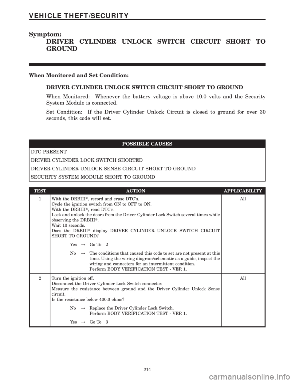
Symptom:
DRIVER CYLINDER UNLOCK SWITCH CIRCUIT SHORT TO
GROUND
When Monitored and Set Condition:
DRIVER CYLINDER UNLOCK SWITCH CIRCUIT SHORT TO GROUND
When Monitored: Whenever the battery voltage is above 10.0 volts and the Security
System Module is connected.
Set Condition: If the Driver Cylinder Unlock Circuit is closed to ground for over 30
seconds, this code will set.
POSSIBLE CAUSES
DTC PRESENT
DRIVER CYLINDER LOCK SWITCH SHORTED
DRIVER CYLINDER UNLOCK SENSE CIRCUIT SHORT TO GROUND
SECURITY SYSTEM MODULE SHORT TO GROUND
TEST ACTION APPLICABILITY
1 With the DRBIIIt, record and erase DTC's.
Cycle the ignition switch from ON to OFF to ON.
With the DRBIIIt, read DTC's.
Lock and unlock the doors from the Driver Cylinder Lock Switch several times while
observing the DRBIIIt.
Wait 10 seconds.
Does the DRBIIItdisplay DRIVER CYLINDER UNLOCK SWITCH CIRCUIT
SHORT TO GROUND?All
Ye s!Go To 2
No!The conditions that caused this code to set are not present at this
time. Using the wiring diagram/schematic as a guide, inspect the
wiring and connectors for an intermittent condition.
Perform BODY VERIFICATION TEST - VER 1.
2 Turn the ignition off.
Disconnect the Driver Cylinder Lock Switch connector.
Measure the resistance between ground and the Driver Cylinder Unlock Sense
circuit.
Is the resistance below 400.0 ohms?All
No!Replace the Driver Cylinder Lock Switch.
Perform BODY VERIFICATION TEST - VER 1.
Ye s!Go To 3
214
VEHICLE THEFT/SECURITY
Page 228 of 2305

TEST ACTION APPLICABILITY
3 Turn the ignition off.
Disconnect the Driver Cylinder Lock Switch connector.
Disconnect the Security System Module.
Measure the resistance between ground and the Driver Cylinder Unlock Sense
circuit.
Is the resistance below 400.0 ohms?All
Ye s!Repair the Driver Cylinder Unlock Sense circuit for a short to
ground.
Perform BODY VERIFICATION TEST - VER 1.
No!Replace the Security System Module.
Perform BODY VERIFICATION TEST - VER 1.
215
VEHICLE THEFT/SECURITY
DRIVER CYLINDER UNLOCK SWITCH CIRCUIT SHORT TO GROUND Ð
Continued
Page 229 of 2305
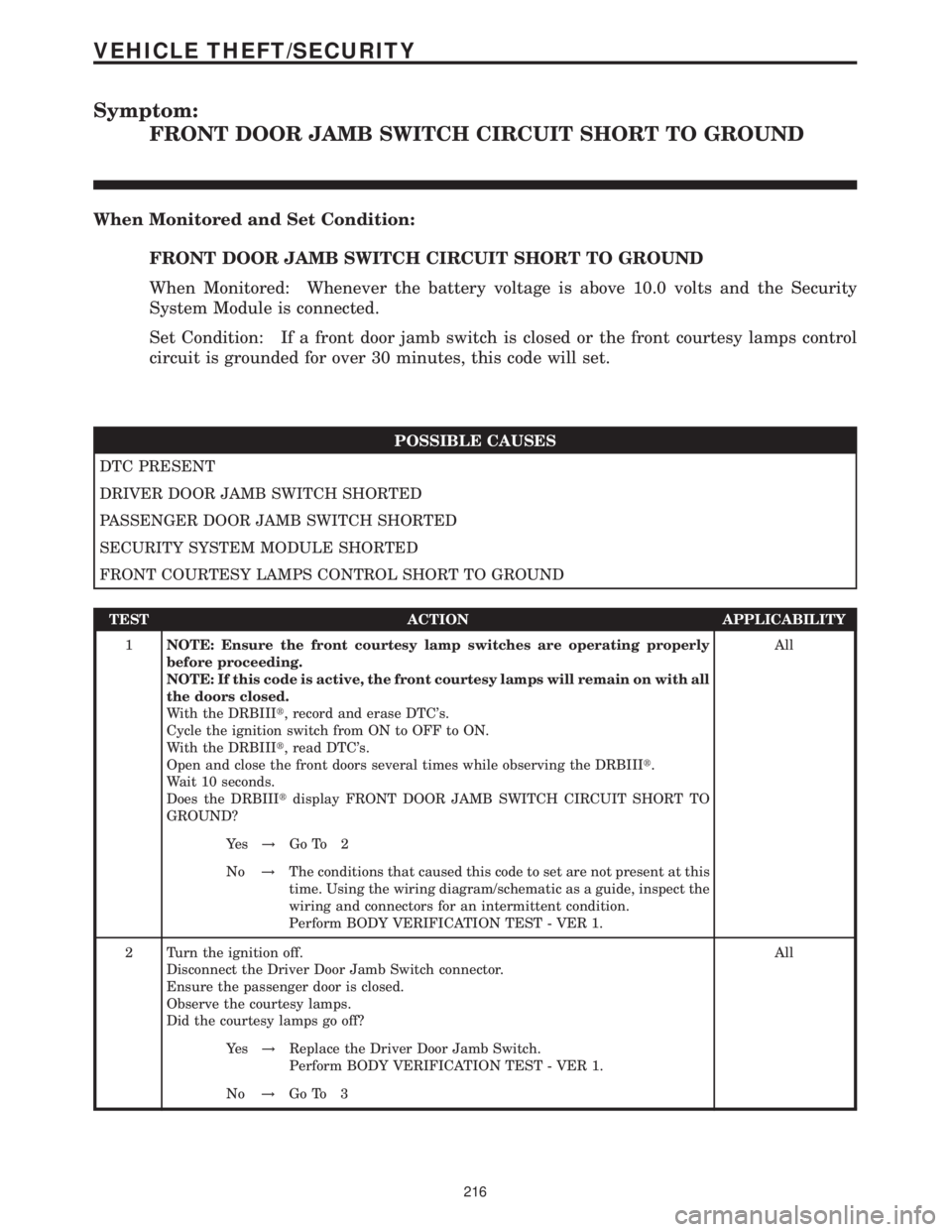
Symptom:
FRONT DOOR JAMB SWITCH CIRCUIT SHORT TO GROUND
When Monitored and Set Condition:
FRONT DOOR JAMB SWITCH CIRCUIT SHORT TO GROUND
When Monitored: Whenever the battery voltage is above 10.0 volts and the Security
System Module is connected.
Set Condition: If a front door jamb switch is closed or the front courtesy lamps control
circuit is grounded for over 30 minutes, this code will set.
POSSIBLE CAUSES
DTC PRESENT
DRIVER DOOR JAMB SWITCH SHORTED
PASSENGER DOOR JAMB SWITCH SHORTED
SECURITY SYSTEM MODULE SHORTED
FRONT COURTESY LAMPS CONTROL SHORT TO GROUND
TEST ACTION APPLICABILITY
1NOTE: Ensure the front courtesy lamp switches are operating properly
before proceeding.
NOTE: If this code is active, the front courtesy lamps will remain on with all
the doors closed.
With the DRBIIIt, record and erase DTC's.
Cycle the ignition switch from ON to OFF to ON.
With the DRBIIIt, read DTC's.
Open and close the front doors several times while observing the DRBIIIt.
Wait 10 seconds.
Does the DRBIIItdisplay FRONT DOOR JAMB SWITCH CIRCUIT SHORT TO
GROUND?All
Ye s!Go To 2
No!The conditions that caused this code to set are not present at this
time. Using the wiring diagram/schematic as a guide, inspect the
wiring and connectors for an intermittent condition.
Perform BODY VERIFICATION TEST - VER 1.
2 Turn the ignition off.
Disconnect the Driver Door Jamb Switch connector.
Ensure the passenger door is closed.
Observe the courtesy lamps.
Did the courtesy lamps go off?All
Ye s!Replace the Driver Door Jamb Switch.
Perform BODY VERIFICATION TEST - VER 1.
No!Go To 3
216
VEHICLE THEFT/SECURITY
Page 230 of 2305
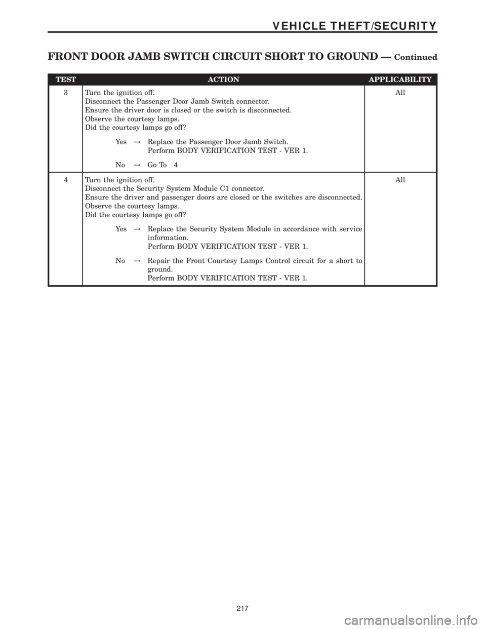
TEST ACTION APPLICABILITY
3 Turn the ignition off.
Disconnect the Passenger Door Jamb Switch connector.
Ensure the driver door is closed or the switch is disconnected.
Observe the courtesy lamps.
Did the courtesy lamps go off?All
Ye s!Replace the Passenger Door Jamb Switch.
Perform BODY VERIFICATION TEST - VER 1.
No!Go To 4
4 Turn the ignition off.
Disconnect the Security System Module C1 connector.
Ensure the driver and passenger doors are closed or the switches are disconnected.
Observe the courtesy lamps.
Did the courtesy lamps go off?All
Ye s!Replace the Security System Module in accordance with service
information.
Perform BODY VERIFICATION TEST - VER 1.
No!Repair the Front Courtesy Lamps Control circuit for a short to
ground.
Perform BODY VERIFICATION TEST - VER 1.
217
VEHICLE THEFT/SECURITY
FRONT DOOR JAMB SWITCH CIRCUIT SHORT TO GROUND ÐContinued