MERCEDES-BENZ SPRINTER 2006 Service Manual
Manufacturer: MERCEDES-BENZ, Model Year: 2006, Model line: SPRINTER, Model: MERCEDES-BENZ SPRINTER 2006Pages: 2305, PDF Size: 48.12 MB
Page 201 of 2305
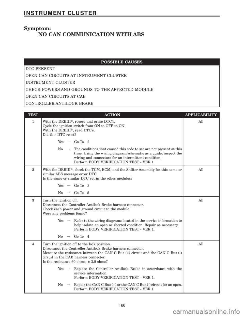
Symptom:
NO CAN COMMUNICATION WITH ABS
POSSIBLE CAUSES
DTC PRESENT
OPEN CAN CIRCUITS AT INSTRUMENT CLUSTER
INSTRUMENT CLUSTER
CHECK POWERS AND GROUNDS TO THE AFFECTED MODULE
OPEN CAN CIRCUITS AT CAB
CONTROLLER ANTILOCK BRAKE
TEST ACTION APPLICABILITY
1 With the DRBIIIt, record and erase DTC's.
Cycle the ignition switch from ON to OFF to ON.
With the DRBIIIt, read DTC's.
Did this DTC reset?All
Ye s!Go To 2
No!The conditions that caused this code to set are not present at this
time. Using the wiring diagram/schematic as a guide, inspect the
wiring and connectors for an intermittent condition.
Perform BODY VERIFICATION TEST - VER 1.
2 With the DRBIIIt, check the TCM, ECM, and the Shifter Assembly for this same or
similar ABS message error DTC.
Is the same or similar DTC set in the other modules?All
Ye s!Go To 3
No!Go To 5
3 Turn the ignition off.
Disconnect the Controller Antilock Brake harness connector.
Check each power and ground circuit to the module.
Were any problems found?All
Ye s!Refer to the wiring diagrams located in the service information to
help isolate an open or shorted condition. Repair as necessary.
Perform BODY VERIFICATION TEST - VER 1.
No!Go To 4
4 Turn the ignition off to the lock position.
Disconnect the Controller Antilock Brake harness connector.
Measure the resistance between the CAN C Bus (+) circuit and the CAN C Bus (-)
circuit in the CAB harness connector.
Is the resistance 60 ohms, 3.0 ohms?All
Ye s!Replace the Controller Antilock Brake in accordance with the
service information.
Perform BODY VERIFICATION TEST - VER 1.
No!Repair the CAN C Bus (+) or the CAN C Bus (-) circuit for an open.
Perform BODY VERIFICATION TEST - VER 1.
188
INSTRUMENT CLUSTER
Page 202 of 2305
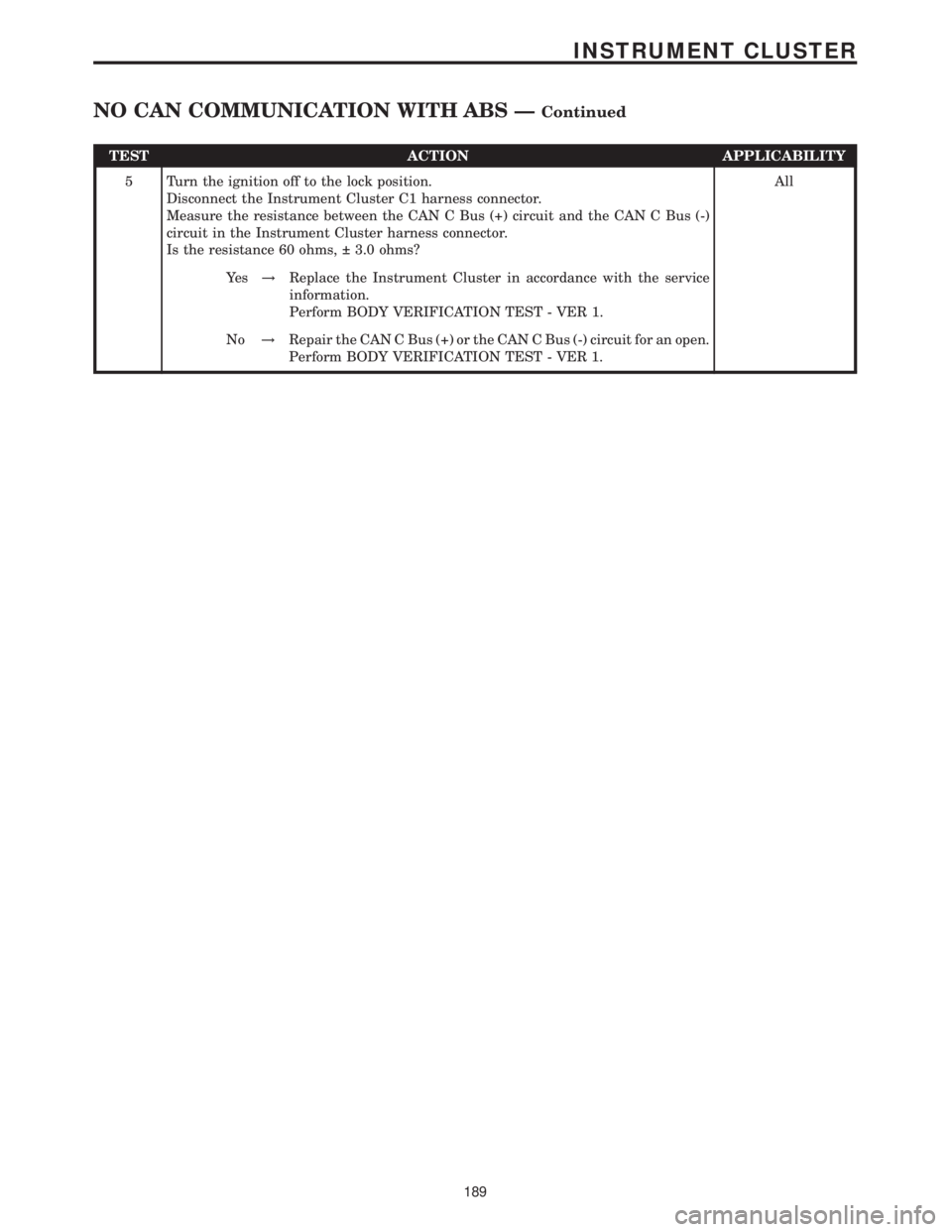
TEST ACTION APPLICABILITY
5 Turn the ignition off to the lock position.
Disconnect the Instrument Cluster C1 harness connector.
Measure the resistance between the CAN C Bus (+) circuit and the CAN C Bus (-)
circuit in the Instrument Cluster harness connector.
Is the resistance 60 ohms, 3.0 ohms?All
Ye s!Replace the Instrument Cluster in accordance with the service
information.
Perform BODY VERIFICATION TEST - VER 1.
No!Repair the CAN C Bus (+) or the CAN C Bus (-) circuit for an open.
Perform BODY VERIFICATION TEST - VER 1.
189
INSTRUMENT CLUSTER
NO CAN COMMUNICATION WITH ABS ÐContinued
Page 203 of 2305
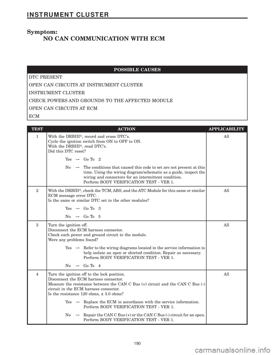
Symptom:
NO CAN COMMUNICATION WITH ECM
POSSIBLE CAUSES
DTC PRESENT
OPEN CAN CIRCUITS AT INSTRUMENT CLUSTER
INSTRUMENT CLUSTER
CHECK POWERS AND GROUNDS TO THE AFFECTED MODULE
OPEN CAN CIRCUITS AT ECM
ECM
TEST ACTION APPLICABILITY
1 With the DRBIIIt, record and erase DTC's.
Cycle the ignition switch from ON to OFF to ON.
With the DRBIIIt, read DTC's.
Did this DTC reset?All
Ye s!Go To 2
No!The conditions that caused this code to set are not present at this
time. Using the wiring diagram/schematic as a guide, inspect the
wiring and connectors for an intermittent condition.
Perform BODY VERIFICATION TEST - VER 1.
2 With the DRBIIIt, check the TCM, ABS, and the ATC Module for this same or similar
ECM message error DTC.
Is the same or similar DTC set in the other modules?All
Ye s!Go To 3
No!Go To 5
3 Turn the ignition off.
Disconnect the ECM harness connector.
Check each power and ground circuit to the module.
Were any problems found?All
Ye s!Refer to the wiring diagrams located in the service information to
help isolate an open or shorted condition. Repair as necessary.
Perform BODY VERIFICATION TEST - VER 1.
No!Go To 4
4 Turn the ignition off to the lock position.
Disconnect the ECM harness connector.
Measure the resistance between the CAN C Bus (+) circuit and the CAN C Bus (-)
circuit in the ECM harness connector.
Is the resistance 120 ohms, 3.0 ohms?All
Ye s!Replace the ECM in accordance with the service information.
Perform BODY VERIFICATION TEST - VER 1.
No!Repair the CAN C Bus (+) or the CAN C Bus (-) circuit for an open.
Perform BODY VERIFICATION TEST - VER 1.
190
INSTRUMENT CLUSTER
Page 204 of 2305
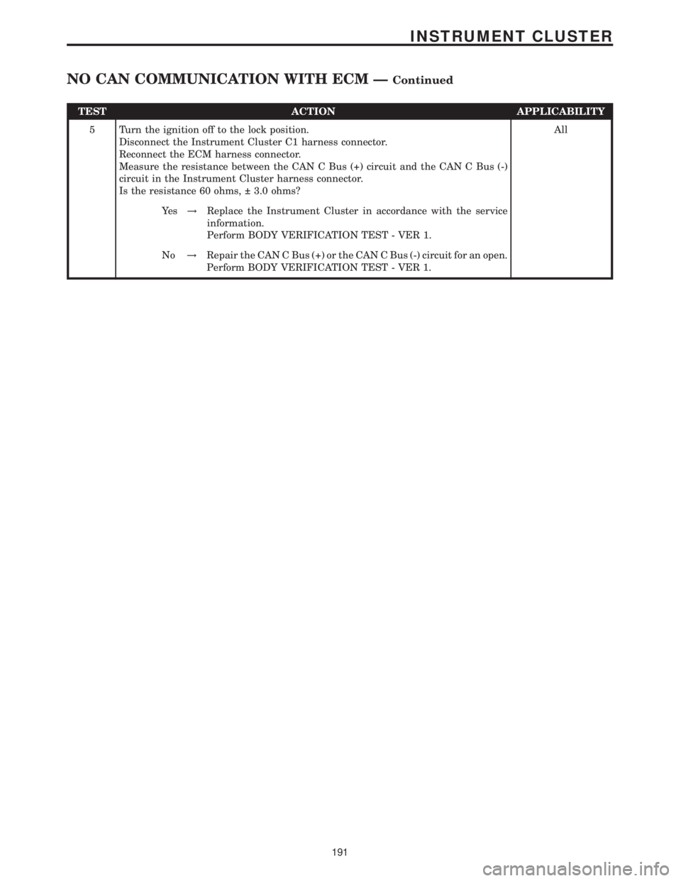
TEST ACTION APPLICABILITY
5 Turn the ignition off to the lock position.
Disconnect the Instrument Cluster C1 harness connector.
Reconnect the ECM harness connector.
Measure the resistance between the CAN C Bus (+) circuit and the CAN C Bus (-)
circuit in the Instrument Cluster harness connector.
Is the resistance 60 ohms, 3.0 ohms?All
Ye s!Replace the Instrument Cluster in accordance with the service
information.
Perform BODY VERIFICATION TEST - VER 1.
No!Repair the CAN C Bus (+) or the CAN C Bus (-) circuit for an open.
Perform BODY VERIFICATION TEST - VER 1.
191
INSTRUMENT CLUSTER
NO CAN COMMUNICATION WITH ECM ÐContinued
Page 205 of 2305
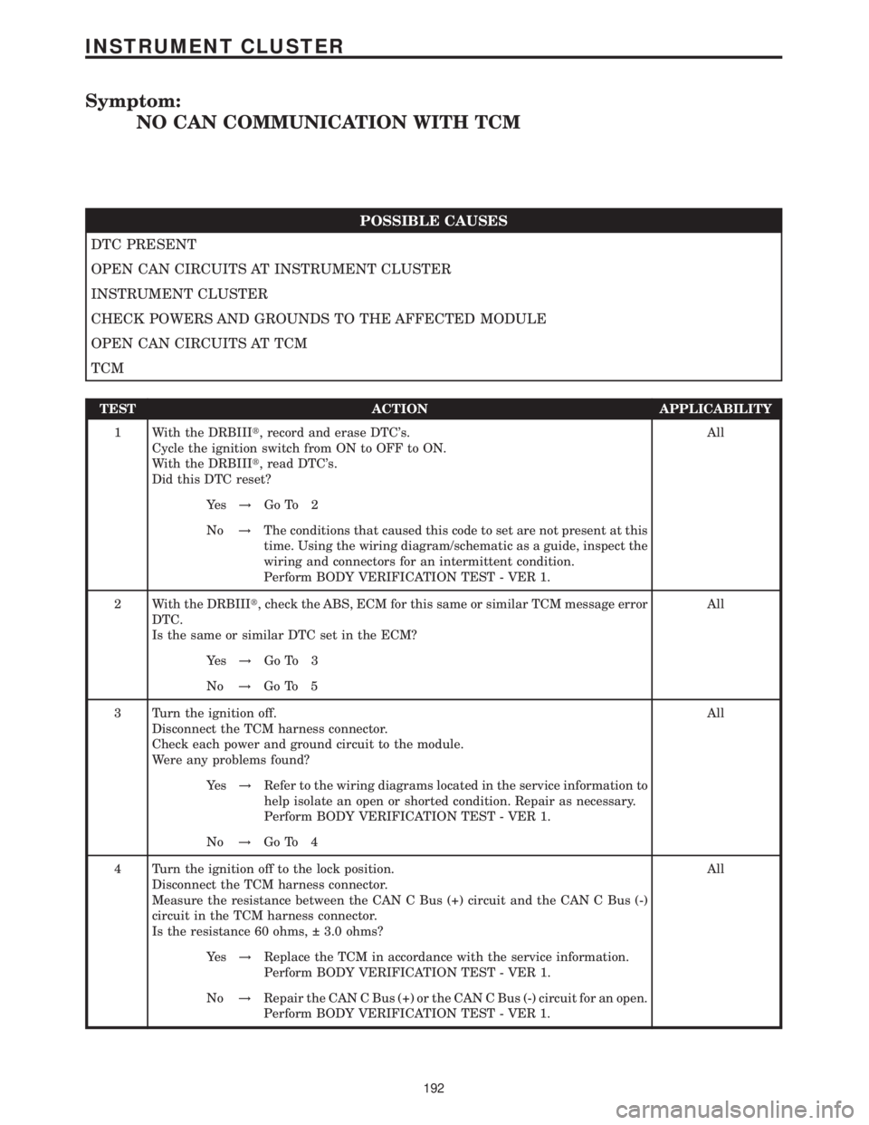
Symptom:
NO CAN COMMUNICATION WITH TCM
POSSIBLE CAUSES
DTC PRESENT
OPEN CAN CIRCUITS AT INSTRUMENT CLUSTER
INSTRUMENT CLUSTER
CHECK POWERS AND GROUNDS TO THE AFFECTED MODULE
OPEN CAN CIRCUITS AT TCM
TCM
TEST ACTION APPLICABILITY
1 With the DRBIIIt, record and erase DTC's.
Cycle the ignition switch from ON to OFF to ON.
With the DRBIIIt, read DTC's.
Did this DTC reset?All
Ye s!Go To 2
No!The conditions that caused this code to set are not present at this
time. Using the wiring diagram/schematic as a guide, inspect the
wiring and connectors for an intermittent condition.
Perform BODY VERIFICATION TEST - VER 1.
2 With the DRBIIIt, check the ABS, ECM for this same or similar TCM message error
DTC.
Is the same or similar DTC set in the ECM?All
Ye s!Go To 3
No!Go To 5
3 Turn the ignition off.
Disconnect the TCM harness connector.
Check each power and ground circuit to the module.
Were any problems found?All
Ye s!Refer to the wiring diagrams located in the service information to
help isolate an open or shorted condition. Repair as necessary.
Perform BODY VERIFICATION TEST - VER 1.
No!Go To 4
4 Turn the ignition off to the lock position.
Disconnect the TCM harness connector.
Measure the resistance between the CAN C Bus (+) circuit and the CAN C Bus (-)
circuit in the TCM harness connector.
Is the resistance 60 ohms, 3.0 ohms?All
Ye s!Replace the TCM in accordance with the service information.
Perform BODY VERIFICATION TEST - VER 1.
No!Repair the CAN C Bus (+) or the CAN C Bus (-) circuit for an open.
Perform BODY VERIFICATION TEST - VER 1.
192
INSTRUMENT CLUSTER
Page 206 of 2305
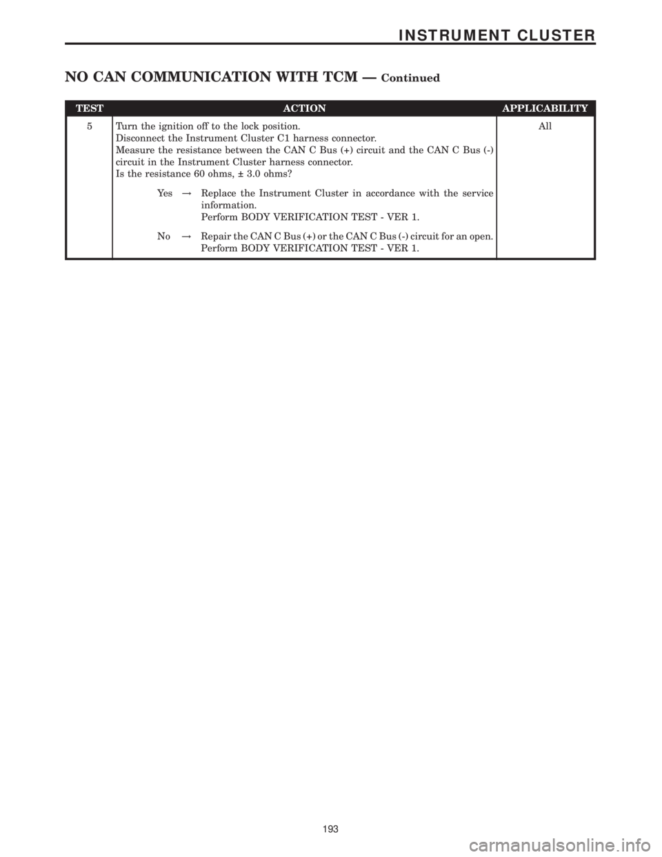
TEST ACTION APPLICABILITY
5 Turn the ignition off to the lock position.
Disconnect the Instrument Cluster C1 harness connector.
Measure the resistance between the CAN C Bus (+) circuit and the CAN C Bus (-)
circuit in the Instrument Cluster harness connector.
Is the resistance 60 ohms, 3.0 ohms?All
Ye s!Replace the Instrument Cluster in accordance with the service
information.
Perform BODY VERIFICATION TEST - VER 1.
No!Repair the CAN C Bus (+) or the CAN C Bus (-) circuit for an open.
Perform BODY VERIFICATION TEST - VER 1.
193
INSTRUMENT CLUSTER
NO CAN COMMUNICATION WITH TCM ÐContinued
Page 207 of 2305
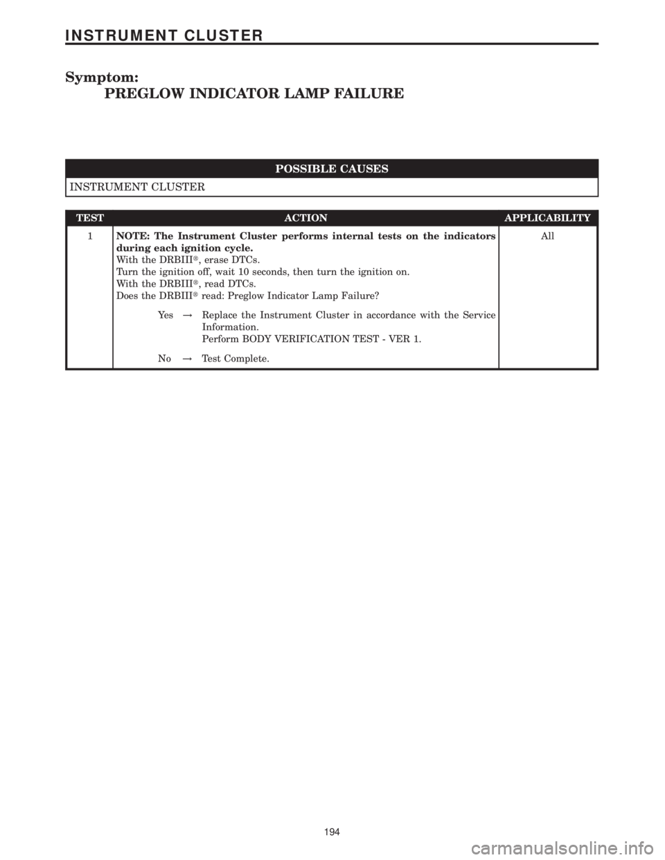
Symptom:
PREGLOW INDICATOR LAMP FAILURE
POSSIBLE CAUSES
INSTRUMENT CLUSTER
TEST ACTION APPLICABILITY
1NOTE: The Instrument Cluster performs internal tests on the indicators
during each ignition cycle.
With the DRBIIIt, erase DTCs.
Turn the ignition off, wait 10 seconds, then turn the ignition on.
With the DRBIIIt, read DTCs.
Does the DRBIIItread: Preglow Indicator Lamp Failure?All
Ye s!Replace the Instrument Cluster in accordance with the Service
Information.
Perform BODY VERIFICATION TEST - VER 1.
No!Test Complete.
194
INSTRUMENT CLUSTER
Page 208 of 2305
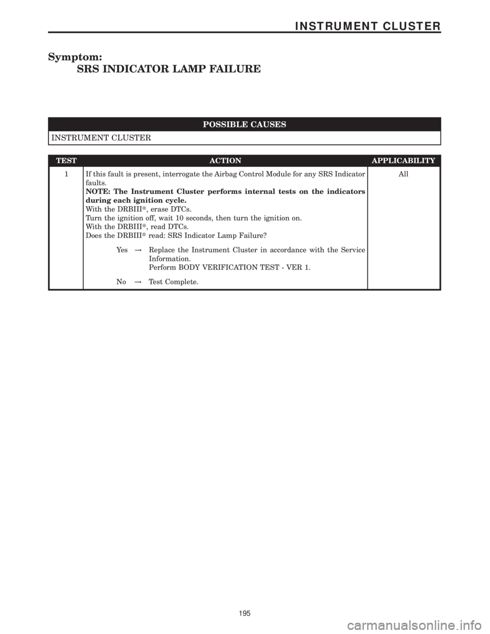
Symptom:
SRS INDICATOR LAMP FAILURE
POSSIBLE CAUSES
INSTRUMENT CLUSTER
TEST ACTION APPLICABILITY
1 If this fault is present, interrogate the Airbag Control Module for any SRS Indicator
faults.
NOTE: The Instrument Cluster performs internal tests on the indicators
during each ignition cycle.
With the DRBIIIt, erase DTCs.
Turn the ignition off, wait 10 seconds, then turn the ignition on.
With the DRBIIIt, read DTCs.
Does the DRBIIItread: SRS Indicator Lamp Failure?All
Ye s!Replace the Instrument Cluster in accordance with the Service
Information.
Perform BODY VERIFICATION TEST - VER 1.
No!Test Complete.
195
INSTRUMENT CLUSTER
Page 209 of 2305
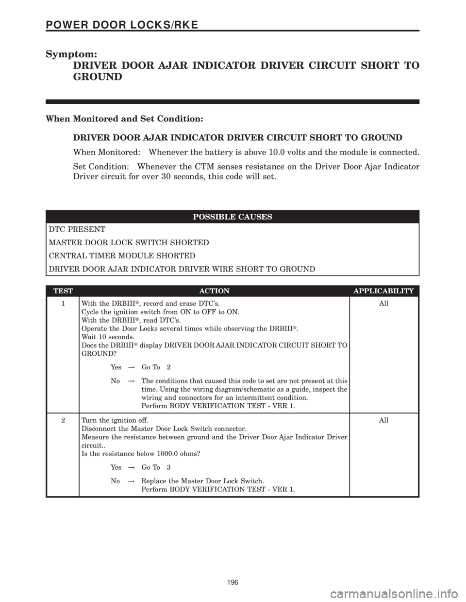
Symptom:
DRIVER DOOR AJAR INDICATOR DRIVER CIRCUIT SHORT TO
GROUND
When Monitored and Set Condition:
DRIVER DOOR AJAR INDICATOR DRIVER CIRCUIT SHORT TO GROUND
When Monitored: Whenever the battery is above 10.0 volts and the module is connected.
Set Condition: Whenever the CTM senses resistance on the Driver Door Ajar Indicator
Driver circuit for over 30 seconds, this code will set.
POSSIBLE CAUSES
DTC PRESENT
MASTER DOOR LOCK SWITCH SHORTED
CENTRAL TIMER MODULE SHORTED
DRIVER DOOR AJAR INDICATOR DRIVER WIRE SHORT TO GROUND
TEST ACTION APPLICABILITY
1 With the DRBIIIt, record and erase DTC's.
Cycle the ignition switch from ON to OFF to ON.
With the DRBIIIt, read DTC's.
Operate the Door Locks several times while observing the DRBIIIt.
Wait 10 seconds.
Does the DRBIIItdisplay DRIVER DOOR AJAR INDICATOR CIRCUIT SHORT TO
GROUND?All
Ye s!Go To 2
No!The conditions that caused this code to set are not present at this
time. Using the wiring diagram/schematic as a guide, inspect the
wiring and connectors for an intermittent condition.
Perform BODY VERIFICATION TEST - VER 1.
2 Turn the ignition off.
Disconnect the Master Door Lock Switch connector.
Measure the resistance between ground and the Driver Door Ajar Indicator Driver
circuit..
Is the resistance below 1000.0 ohms?All
Ye s!Go To 3
No!Replace the Master Door Lock Switch.
Perform BODY VERIFICATION TEST - VER 1.
196
POWER DOOR LOCKS/RKE
Page 210 of 2305
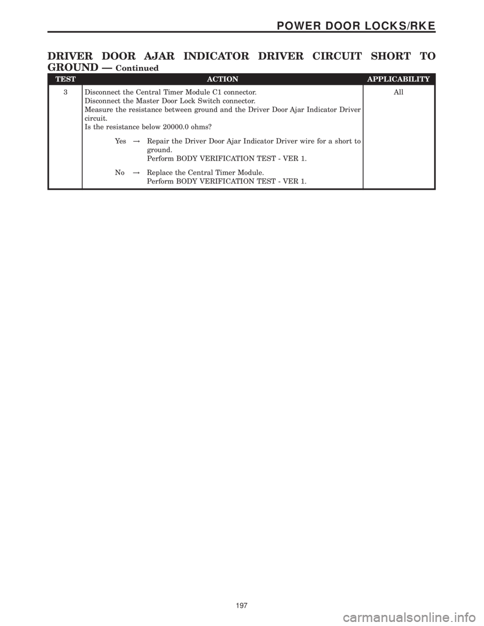
TEST ACTION APPLICABILITY
3 Disconnect the Central Timer Module C1 connector.
Disconnect the Master Door Lock Switch connector.
Measure the resistance between ground and the Driver Door Ajar Indicator Driver
circuit.
Is the resistance below 20000.0 ohms?All
Ye s!Repair the Driver Door Ajar Indicator Driver wire for a short to
ground.
Perform BODY VERIFICATION TEST - VER 1.
No!Replace the Central Timer Module.
Perform BODY VERIFICATION TEST - VER 1.
197
POWER DOOR LOCKS/RKE
DRIVER DOOR AJAR INDICATOR DRIVER CIRCUIT SHORT TO
GROUND Ð
Continued