MERCEDES-BENZ SPRINTER 2006 Service Manual
Manufacturer: MERCEDES-BENZ, Model Year: 2006, Model line: SPRINTER, Model: MERCEDES-BENZ SPRINTER 2006Pages: 2305, PDF Size: 48.12 MB
Page 161 of 2305
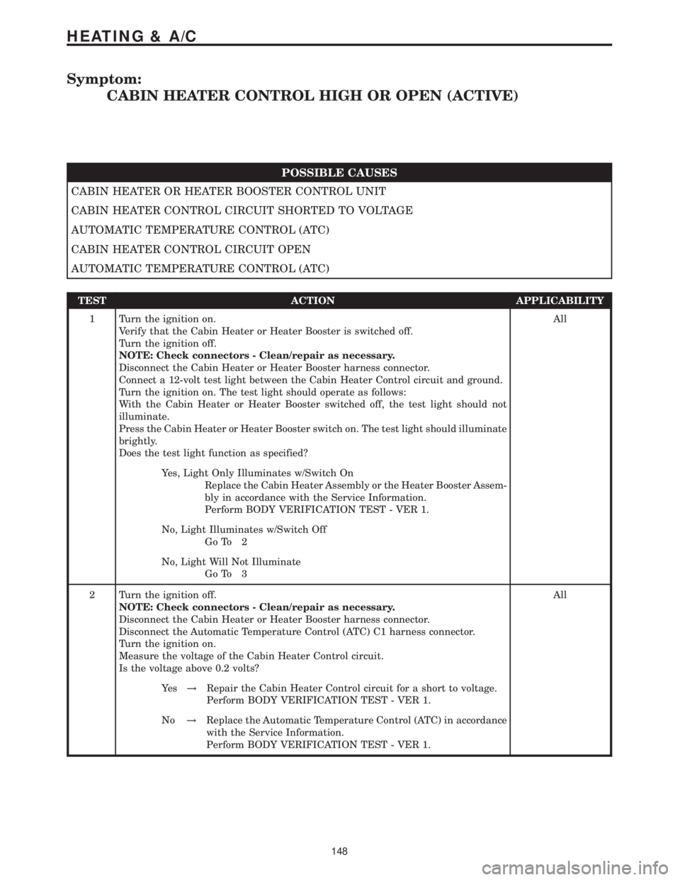
Symptom:
CABIN HEATER CONTROL HIGH OR OPEN (ACTIVE)
POSSIBLE CAUSES
CABIN HEATER OR HEATER BOOSTER CONTROL UNIT
CABIN HEATER CONTROL CIRCUIT SHORTED TO VOLTAGE
AUTOMATIC TEMPERATURE CONTROL (ATC)
CABIN HEATER CONTROL CIRCUIT OPEN
AUTOMATIC TEMPERATURE CONTROL (ATC)
TEST ACTION APPLICABILITY
1 Turn the ignition on.
Verify that the Cabin Heater or Heater Booster is switched off.
Turn the ignition off.
NOTE: Check connectors - Clean/repair as necessary.
Disconnect the Cabin Heater or Heater Booster harness connector.
Connect a 12-volt test light between the Cabin Heater Control circuit and ground.
Turn the ignition on. The test light should operate as follows:
With the Cabin Heater or Heater Booster switched off, the test light should not
illuminate.
Press the Cabin Heater or Heater Booster switch on. The test light should illuminate
brightly.
Does the test light function as specified?All
Yes, Light Only Illuminates w/Switch On
Replace the Cabin Heater Assembly or the Heater Booster Assem-
bly in accordance with the Service Information.
Perform BODY VERIFICATION TEST - VER 1.
No, Light Illuminates w/Switch Off
Go To 2
No, Light Will Not Illuminate
Go To 3
2 Turn the ignition off.
NOTE: Check connectors - Clean/repair as necessary.
Disconnect the Cabin Heater or Heater Booster harness connector.
Disconnect the Automatic Temperature Control (ATC) C1 harness connector.
Turn the ignition on.
Measure the voltage of the Cabin Heater Control circuit.
Is the voltage above 0.2 volts?All
Ye s!Repair the Cabin Heater Control circuit for a short to voltage.
Perform BODY VERIFICATION TEST - VER 1.
No!Replace the Automatic Temperature Control (ATC) in accordance
with the Service Information.
Perform BODY VERIFICATION TEST - VER 1.
148
HEATING & A/C
Page 162 of 2305
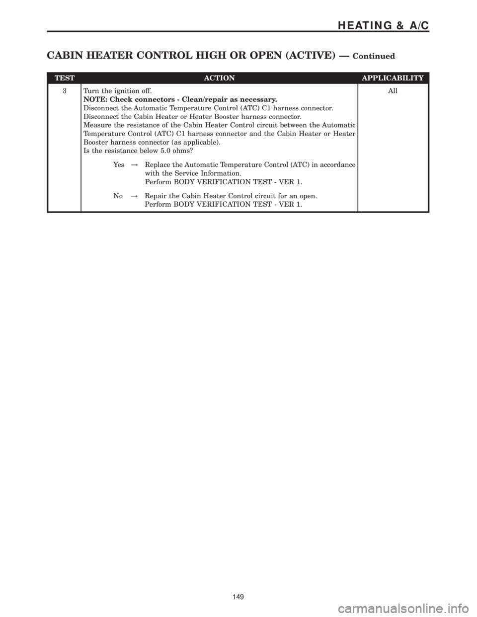
TEST ACTION APPLICABILITY
3 Turn the ignition off.
NOTE: Check connectors - Clean/repair as necessary.
Disconnect the Automatic Temperature Control (ATC) C1 harness connector.
Disconnect the Cabin Heater or Heater Booster harness connector.
Measure the resistance of the Cabin Heater Control circuit between the Automatic
Temperature Control (ATC) C1 harness connector and the Cabin Heater or Heater
Booster harness connector (as applicable).
Is the resistance below 5.0 ohms?All
Ye s!Replace the Automatic Temperature Control (ATC) in accordance
with the Service Information.
Perform BODY VERIFICATION TEST - VER 1.
No!Repair the Cabin Heater Control circuit for an open.
Perform BODY VERIFICATION TEST - VER 1.
149
HEATING & A/C
CABIN HEATER CONTROL HIGH OR OPEN (ACTIVE) ÐContinued
Page 163 of 2305
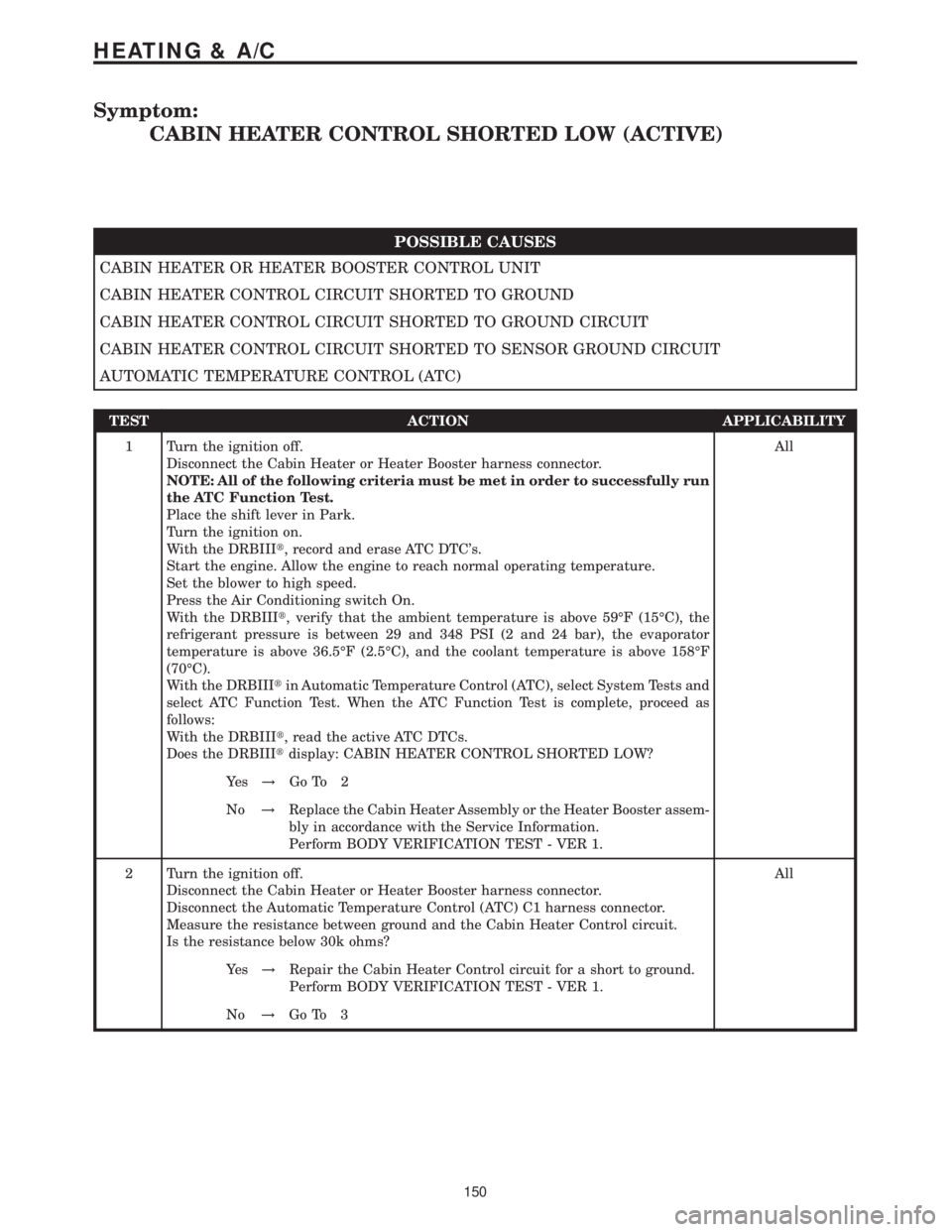
Symptom:
CABIN HEATER CONTROL SHORTED LOW (ACTIVE)
POSSIBLE CAUSES
CABIN HEATER OR HEATER BOOSTER CONTROL UNIT
CABIN HEATER CONTROL CIRCUIT SHORTED TO GROUND
CABIN HEATER CONTROL CIRCUIT SHORTED TO GROUND CIRCUIT
CABIN HEATER CONTROL CIRCUIT SHORTED TO SENSOR GROUND CIRCUIT
AUTOMATIC TEMPERATURE CONTROL (ATC)
TEST ACTION APPLICABILITY
1 Turn the ignition off.
Disconnect the Cabin Heater or Heater Booster harness connector.
NOTE: All of the following criteria must be met in order to successfully run
the ATC Function Test.
Place the shift lever in Park.
Turn the ignition on.
With the DRBIIIt, record and erase ATC DTC's.
Start the engine. Allow the engine to reach normal operating temperature.
Set the blower to high speed.
Press the Air Conditioning switch On.
With the DRBIIIt, verify that the ambient temperature is above 59ÉF (15ÉC), the
refrigerant pressure is between 29 and 348 PSI (2 and 24 bar), the evaporator
temperature is above 36.5ÉF (2.5ÉC), and the coolant temperature is above 158ÉF
(70ÉC).
With the DRBIIItin Automatic Temperature Control (ATC), select System Tests and
select ATC Function Test. When the ATC Function Test is complete, proceed as
follows:
With the DRBIIIt, read the active ATC DTCs.
Does the DRBIIItdisplay: CABIN HEATER CONTROL SHORTED LOW?All
Ye s!Go To 2
No!Replace the Cabin Heater Assembly or the Heater Booster assem-
bly in accordance with the Service Information.
Perform BODY VERIFICATION TEST - VER 1.
2 Turn the ignition off.
Disconnect the Cabin Heater or Heater Booster harness connector.
Disconnect the Automatic Temperature Control (ATC) C1 harness connector.
Measure the resistance between ground and the Cabin Heater Control circuit.
Is the resistance below 30k ohms?All
Ye s!Repair the Cabin Heater Control circuit for a short to ground.
Perform BODY VERIFICATION TEST - VER 1.
No!Go To 3
150
HEATING & A/C
Page 164 of 2305
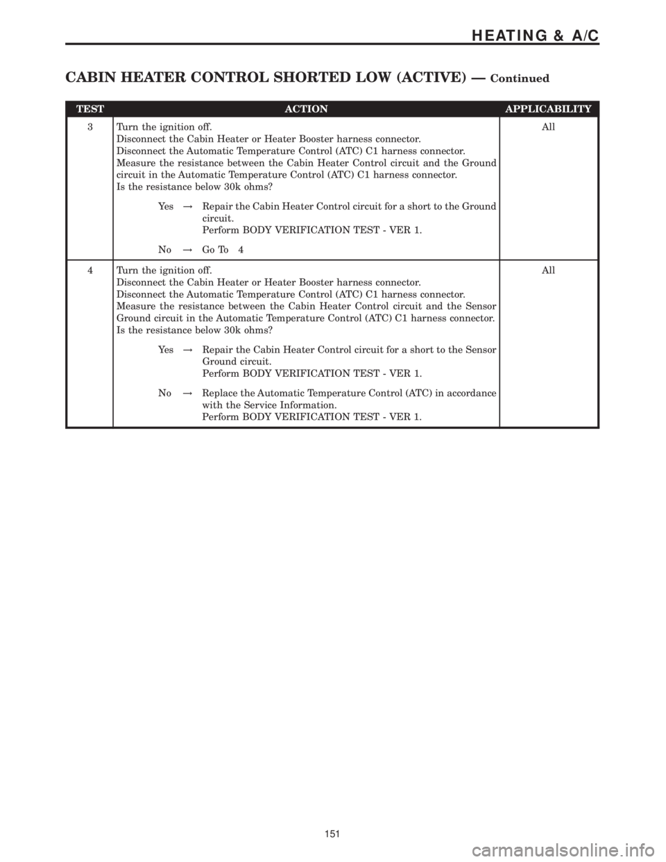
TEST ACTION APPLICABILITY
3 Turn the ignition off.
Disconnect the Cabin Heater or Heater Booster harness connector.
Disconnect the Automatic Temperature Control (ATC) C1 harness connector.
Measure the resistance between the Cabin Heater Control circuit and the Ground
circuit in the Automatic Temperature Control (ATC) C1 harness connector.
Is the resistance below 30k ohms?All
Ye s!Repair the Cabin Heater Control circuit for a short to the Ground
circuit.
Perform BODY VERIFICATION TEST - VER 1.
No!Go To 4
4 Turn the ignition off.
Disconnect the Cabin Heater or Heater Booster harness connector.
Disconnect the Automatic Temperature Control (ATC) C1 harness connector.
Measure the resistance between the Cabin Heater Control circuit and the Sensor
Ground circuit in the Automatic Temperature Control (ATC) C1 harness connector.
Is the resistance below 30k ohms?All
Ye s!Repair the Cabin Heater Control circuit for a short to the Sensor
Ground circuit.
Perform BODY VERIFICATION TEST - VER 1.
No!Replace the Automatic Temperature Control (ATC) in accordance
with the Service Information.
Perform BODY VERIFICATION TEST - VER 1.
151
HEATING & A/C
CABIN HEATER CONTROL SHORTED LOW (ACTIVE) ÐContinued
Page 165 of 2305
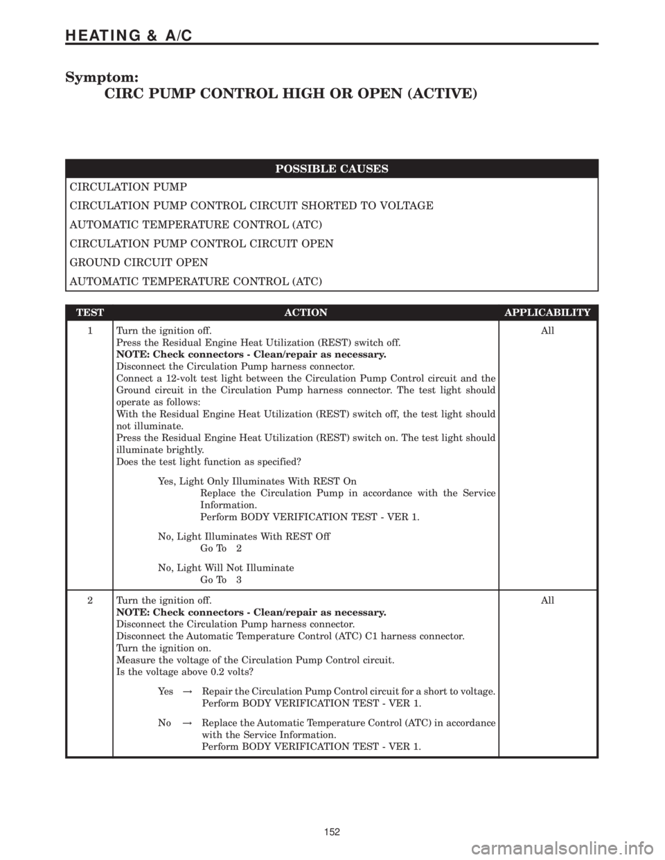
Symptom:
CIRC PUMP CONTROL HIGH OR OPEN (ACTIVE)
POSSIBLE CAUSES
CIRCULATION PUMP
CIRCULATION PUMP CONTROL CIRCUIT SHORTED TO VOLTAGE
AUTOMATIC TEMPERATURE CONTROL (ATC)
CIRCULATION PUMP CONTROL CIRCUIT OPEN
GROUND CIRCUIT OPEN
AUTOMATIC TEMPERATURE CONTROL (ATC)
TEST ACTION APPLICABILITY
1 Turn the ignition off.
Press the Residual Engine Heat Utilization (REST) switch off.
NOTE: Check connectors - Clean/repair as necessary.
Disconnect the Circulation Pump harness connector.
Connect a 12-volt test light between the Circulation Pump Control circuit and the
Ground circuit in the Circulation Pump harness connector. The test light should
operate as follows:
With the Residual Engine Heat Utilization (REST) switch off, the test light should
not illuminate.
Press the Residual Engine Heat Utilization (REST) switch on. The test light should
illuminate brightly.
Does the test light function as specified?All
Yes, Light Only Illuminates With REST On
Replace the Circulation Pump in accordance with the Service
Information.
Perform BODY VERIFICATION TEST - VER 1.
No, Light Illuminates With REST Off
Go To 2
No, Light Will Not Illuminate
Go To 3
2 Turn the ignition off.
NOTE: Check connectors - Clean/repair as necessary.
Disconnect the Circulation Pump harness connector.
Disconnect the Automatic Temperature Control (ATC) C1 harness connector.
Turn the ignition on.
Measure the voltage of the Circulation Pump Control circuit.
Is the voltage above 0.2 volts?All
Ye s!Repair the Circulation Pump Control circuit for a short to voltage.
Perform BODY VERIFICATION TEST - VER 1.
No!Replace the Automatic Temperature Control (ATC) in accordance
with the Service Information.
Perform BODY VERIFICATION TEST - VER 1.
152
HEATING & A/C
Page 166 of 2305
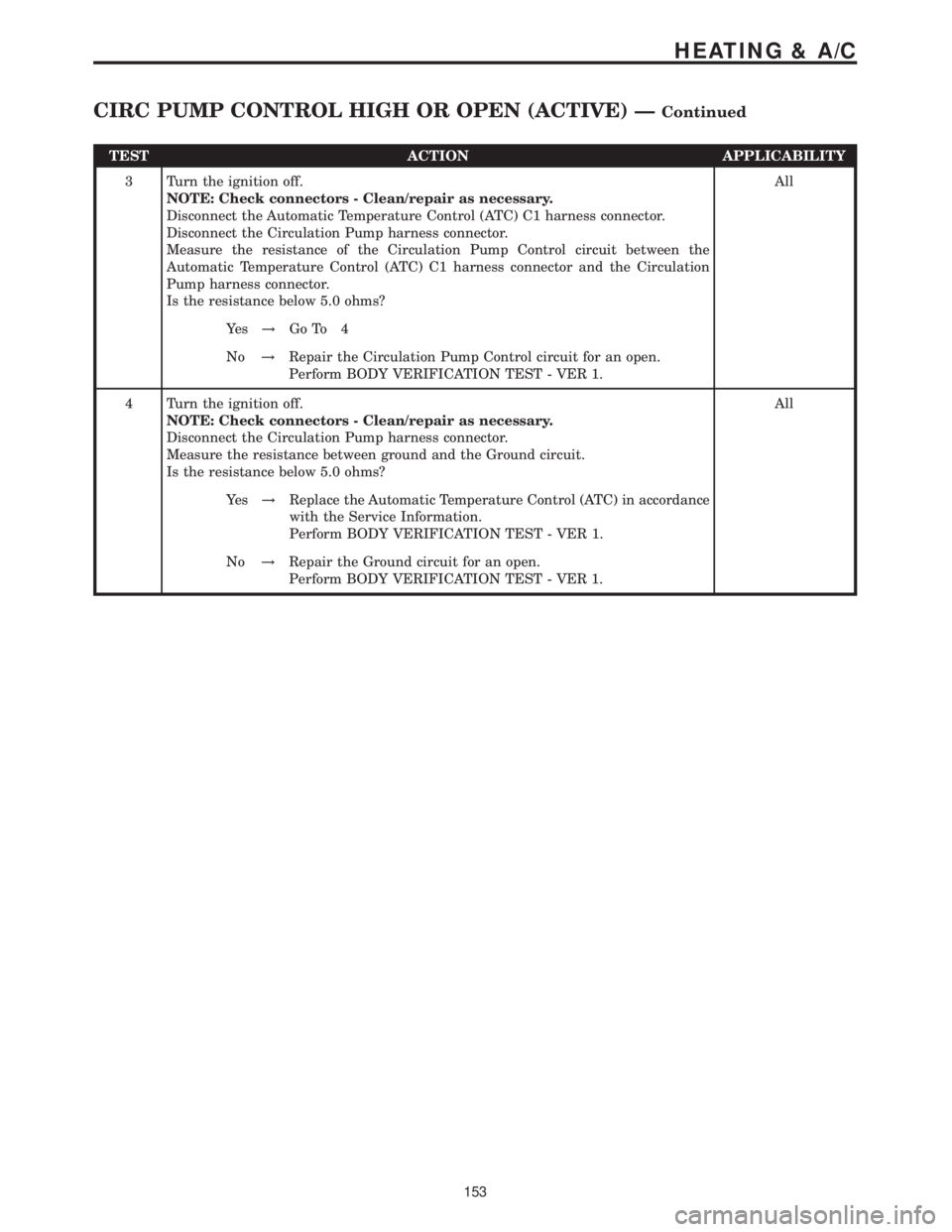
TEST ACTION APPLICABILITY
3 Turn the ignition off.
NOTE: Check connectors - Clean/repair as necessary.
Disconnect the Automatic Temperature Control (ATC) C1 harness connector.
Disconnect the Circulation Pump harness connector.
Measure the resistance of the Circulation Pump Control circuit between the
Automatic Temperature Control (ATC) C1 harness connector and the Circulation
Pump harness connector.
Is the resistance below 5.0 ohms?All
Ye s!Go To 4
No!Repair the Circulation Pump Control circuit for an open.
Perform BODY VERIFICATION TEST - VER 1.
4 Turn the ignition off.
NOTE: Check connectors - Clean/repair as necessary.
Disconnect the Circulation Pump harness connector.
Measure the resistance between ground and the Ground circuit.
Is the resistance below 5.0 ohms?All
Ye s!Replace the Automatic Temperature Control (ATC) in accordance
with the Service Information.
Perform BODY VERIFICATION TEST - VER 1.
No!Repair the Ground circuit for an open.
Perform BODY VERIFICATION TEST - VER 1.
153
HEATING & A/C
CIRC PUMP CONTROL HIGH OR OPEN (ACTIVE) ÐContinued
Page 167 of 2305
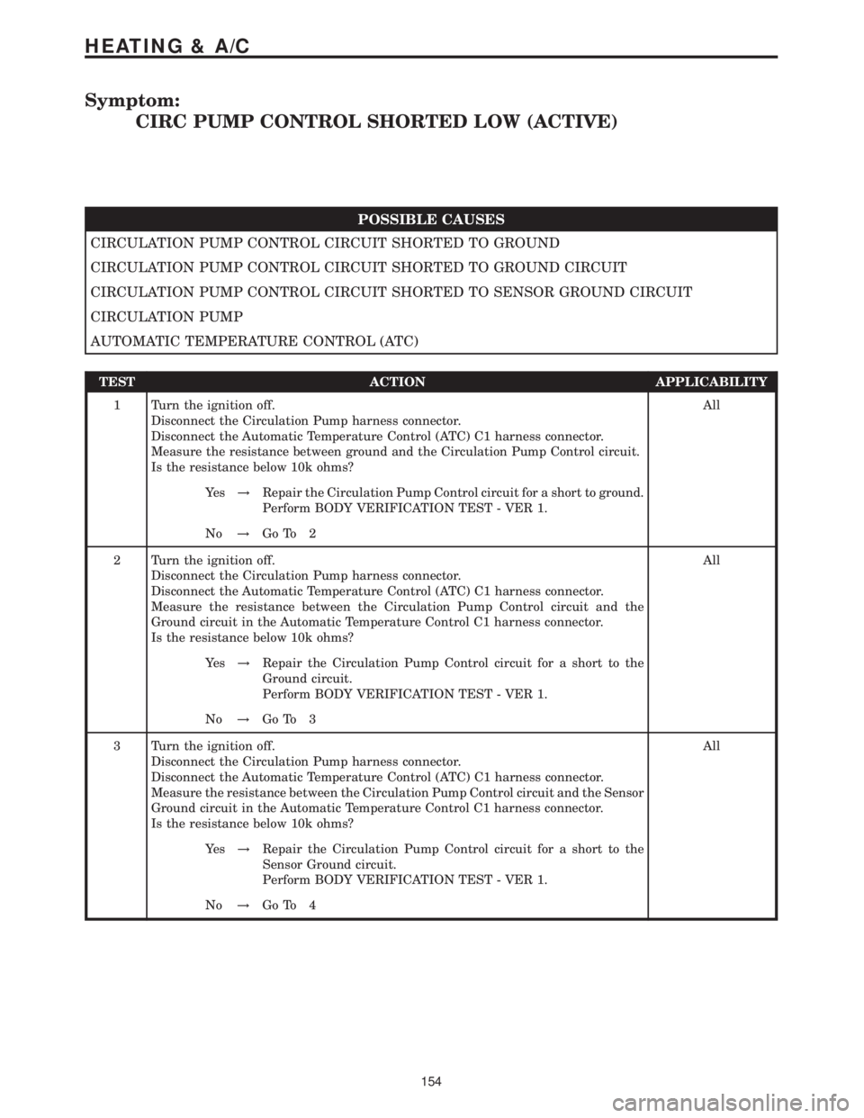
Symptom:
CIRC PUMP CONTROL SHORTED LOW (ACTIVE)
POSSIBLE CAUSES
CIRCULATION PUMP CONTROL CIRCUIT SHORTED TO GROUND
CIRCULATION PUMP CONTROL CIRCUIT SHORTED TO GROUND CIRCUIT
CIRCULATION PUMP CONTROL CIRCUIT SHORTED TO SENSOR GROUND CIRCUIT
CIRCULATION PUMP
AUTOMATIC TEMPERATURE CONTROL (ATC)
TEST ACTION APPLICABILITY
1 Turn the ignition off.
Disconnect the Circulation Pump harness connector.
Disconnect the Automatic Temperature Control (ATC) C1 harness connector.
Measure the resistance between ground and the Circulation Pump Control circuit.
Is the resistance below 10k ohms?All
Ye s!Repair the Circulation Pump Control circuit for a short to ground.
Perform BODY VERIFICATION TEST - VER 1.
No!Go To 2
2 Turn the ignition off.
Disconnect the Circulation Pump harness connector.
Disconnect the Automatic Temperature Control (ATC) C1 harness connector.
Measure the resistance between the Circulation Pump Control circuit and the
Ground circuit in the Automatic Temperature Control C1 harness connector.
Is the resistance below 10k ohms?All
Ye s!Repair the Circulation Pump Control circuit for a short to the
Ground circuit.
Perform BODY VERIFICATION TEST - VER 1.
No!Go To 3
3 Turn the ignition off.
Disconnect the Circulation Pump harness connector.
Disconnect the Automatic Temperature Control (ATC) C1 harness connector.
Measure the resistance between the Circulation Pump Control circuit and the Sensor
Ground circuit in the Automatic Temperature Control C1 harness connector.
Is the resistance below 10k ohms?All
Ye s!Repair the Circulation Pump Control circuit for a short to the
Sensor Ground circuit.
Perform BODY VERIFICATION TEST - VER 1.
No!Go To 4
154
HEATING & A/C
Page 168 of 2305
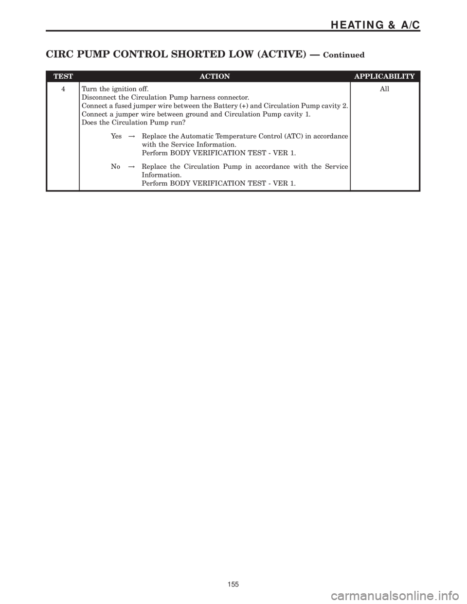
TEST ACTION APPLICABILITY
4 Turn the ignition off.
Disconnect the Circulation Pump harness connector.
Connect a fused jumper wire between the Battery (+) and Circulation Pump cavity 2.
Connect a jumper wire between ground and Circulation Pump cavity 1.
Does the Circulation Pump run?All
Ye s!Replace the Automatic Temperature Control (ATC) in accordance
with the Service Information.
Perform BODY VERIFICATION TEST - VER 1.
No!Replace the Circulation Pump in accordance with the Service
Information.
Perform BODY VERIFICATION TEST - VER 1.
155
HEATING & A/C
CIRC PUMP CONTROL SHORTED LOW (ACTIVE) ÐContinued
Page 169 of 2305
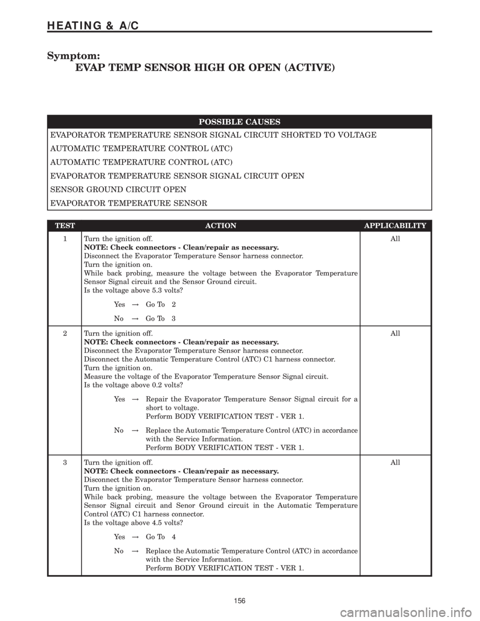
Symptom:
EVAP TEMP SENSOR HIGH OR OPEN (ACTIVE)
POSSIBLE CAUSES
EVAPORATOR TEMPERATURE SENSOR SIGNAL CIRCUIT SHORTED TO VOLTAGE
AUTOMATIC TEMPERATURE CONTROL (ATC)
AUTOMATIC TEMPERATURE CONTROL (ATC)
EVAPORATOR TEMPERATURE SENSOR SIGNAL CIRCUIT OPEN
SENSOR GROUND CIRCUIT OPEN
EVAPORATOR TEMPERATURE SENSOR
TEST ACTION APPLICABILITY
1 Turn the ignition off.
NOTE: Check connectors - Clean/repair as necessary.
Disconnect the Evaporator Temperature Sensor harness connector.
Turn the ignition on.
While back probing, measure the voltage between the Evaporator Temperature
Sensor Signal circuit and the Sensor Ground circuit.
Is the voltage above 5.3 volts?All
Ye s!Go To 2
No!Go To 3
2 Turn the ignition off.
NOTE: Check connectors - Clean/repair as necessary.
Disconnect the Evaporator Temperature Sensor harness connector.
Disconnect the Automatic Temperature Control (ATC) C1 harness connector.
Turn the ignition on.
Measure the voltage of the Evaporator Temperature Sensor Signal circuit.
Is the voltage above 0.2 volts?All
Ye s!Repair the Evaporator Temperature Sensor Signal circuit for a
short to voltage.
Perform BODY VERIFICATION TEST - VER 1.
No!Replace the Automatic Temperature Control (ATC) in accordance
with the Service Information.
Perform BODY VERIFICATION TEST - VER 1.
3 Turn the ignition off.
NOTE: Check connectors - Clean/repair as necessary.
Disconnect the Evaporator Temperature Sensor harness connector.
Turn the ignition on.
While back probing, measure the voltage between the Evaporator Temperature
Sensor Signal circuit and Senor Ground circuit in the Automatic Temperature
Control (ATC) C1 harness connector.
Is the voltage above 4.5 volts?All
Ye s!Go To 4
No!Replace the Automatic Temperature Control (ATC) in accordance
with the Service Information.
Perform BODY VERIFICATION TEST - VER 1.
156
HEATING & A/C
Page 170 of 2305
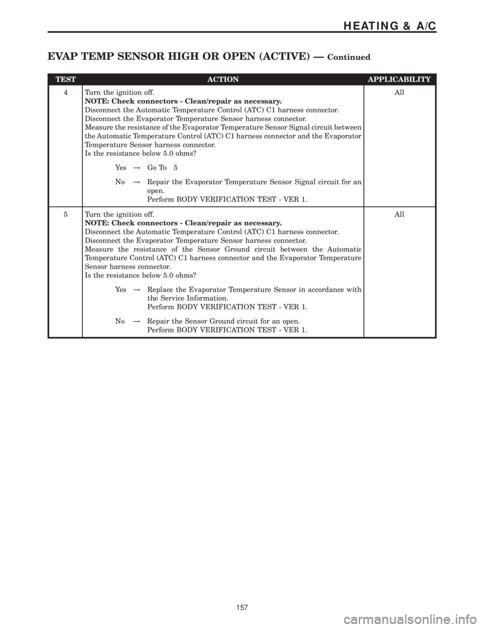
TEST ACTION APPLICABILITY
4 Turn the ignition off.
NOTE: Check connectors - Clean/repair as necessary.
Disconnect the Automatic Temperature Control (ATC) C1 harness connector.
Disconnect the Evaporator Temperature Sensor harness connector.
Measure the resistance of the Evaporator Temperature Sensor Signal circuit between
the Automatic Temperature Control (ATC) C1 harness connector and the Evaporator
Temperature Sensor harness connector.
Is the resistance below 5.0 ohms?All
Ye s!Go To 5
No!Repair the Evaporator Temperature Sensor Signal circuit for an
open.
Perform BODY VERIFICATION TEST - VER 1.
5 Turn the ignition off.
NOTE: Check connectors - Clean/repair as necessary.
Disconnect the Automatic Temperature Control (ATC) C1 harness connector.
Disconnect the Evaporator Temperature Sensor harness connector.
Measure the resistance of the Sensor Ground circuit between the Automatic
Temperature Control (ATC) C1 harness connector and the Evaporator Temperature
Sensor harness connector.
Is the resistance below 5.0 ohms?All
Ye s!Replace the Evaporator Temperature Sensor in accordance with
the Service Information.
Perform BODY VERIFICATION TEST - VER 1.
No!Repair the Sensor Ground circuit for an open.
Perform BODY VERIFICATION TEST - VER 1.
157
HEATING & A/C
EVAP TEMP SENSOR HIGH OR OPEN (ACTIVE) ÐContinued