MERCEDES-BENZ SPRINTER 2006 Service Manual
Manufacturer: MERCEDES-BENZ, Model Year: 2006, Model line: SPRINTER, Model: MERCEDES-BENZ SPRINTER 2006Pages: 2305, PDF Size: 48.12 MB
Page 2021 of 2305
described in Step 4. Allow clear top coat to dry hard.
If desired, Step 5 can be performed on clear top coat.
WARNING: AVOID PROLONGED SKIN CONTACT
WITH PETROLEUM OR ALCOHOL ± BASED CLEAN-
ING SOLVENTS. PERSONAL INJURY CAN
RESULT.AVOID PROLONGED SKIN CONTACT WITH
PETROLEUM OR ALCOHOL ± BASED CLEANING
SOLVENTS. PERSONAL INJURY CAN RESULT.
FINESSE SANDING / BUFFING
& POLISH
DESCRIPTION
CAUTION: Do not remove more than.5 mils of
clearcoat finish, if equipped. Basecoat paint must
retain clearcoat for durability.
Use a Paint Thickness Gauge #PR-ETG-2X or equiv-
alent to determine film thickness before and after
the repair.
Minor acid etching, orange peel, or smudging in
clearcoat or single-stage finishes can be reduced with
light finesse sanding, hand buffing, and polishing.If
the finish has been finesse sanded in the past,
it cannot be repeated. Finesse sanding opera-
tion should be performed by a trained automo-
tive paint technician.
23 - 78 PAINTVA
Page 2022 of 2305
SEATS
TABLE OF CONTENTS
page page
ARMREST
REMOVAL.............................79
INSTALLATION.........................79
HEADREST
REMOVAL.............................79
INSTALLATION.........................79
SEAT - FRONT
REMOVAL.............................79
INSTALLATION.........................80
SEAT BACK - FRONT
REMOVAL.............................80
INSTALLATION.........................80
SEAT CUSHION - FRONT
REMOVAL.............................80
INSTALLATION.........................81SEAT ADJUSTERS - FRONT
REMOVAL.............................81
INSTALLATION.........................81
SEAT - REAR
REMOVAL.............................81
INSTALLATION.........................82
REAR SEAT BACK SHIELD
REMOVAL.............................82
INSTALLATION.........................82
SEAT BACK CUSHION/COVER - REAR
REMOVAL.............................82
INSTALLATION.........................82
SEAT CUSHION/COVER - REAR
REMOVAL.............................83
INSTALLATION.........................83
ARMREST
REMOVAL
(1) Remove the screws and remove the armrest
cover.
(2) Remove the three bolts and remove the arm-
rest from the seat back.
INSTALLATION
(1) Install the armrest and install the three bolts.
(2) Install the armrest cover and install the
screws.
HEADREST
REMOVAL
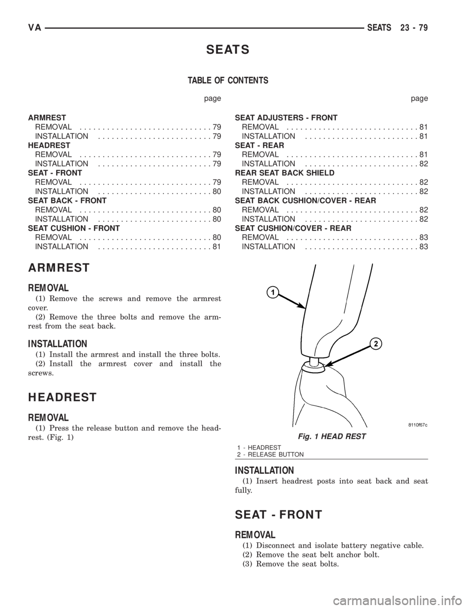
(1) Press the release button and remove the head-
rest. (Fig. 1)
INSTALLATION
(1) Insert headrest posts into seat back and seat
fully.
SEAT - FRONT
REMOVAL
(1) Disconnect and isolate battery negative cable.
(2) Remove the seat belt anchor bolt.
(3) Remove the seat bolts.
Fig. 1 HEAD REST
1 - HEADREST
2 - RELEASE BUTTON
VASEATS 23 - 79
Page 2023 of 2305

(4) Disconnect the electrical connectors, if
equipped.
INSTALLATION
(1) Position seat in vehicle and connect the electri-
cal connectors, if equipped.
(2) Install the mounting bolts and tighten to 25
N´m (18 ft. lbs.).
(3) Install the seat belt anchor and bolt.
(4) Tighten anchor bolt to 35 N´m (26 ft. lbs.).
(5) Connect battery negative cable.
SEAT BACK - FRONT
REMOVAL
(1) Disconnect and isolate battery negative cable.
(2) Remove seat cushion. (Refer to 23 - BODY/
SEATS/SEAT CUSHION - FRONT - REMOVAL)
(3) Verify that seat back is in full upright position.
(4) Disconnect lumbar support hose, if equipped.
(Fig. 3)
(5) Remove seat back bolts and remove seat
back.
INSTALLATION
(1) Remove stop screw.
(2) Install seat back locking spline side first.
NOTE: For better centering of seat back in the
mounting bore during installation, operate the seat
back release lever once.
(3) Install the spline side seat back bolt.
(4) Install remaining seat back side.
NOTE: It may be necessary to press the guide tabs
apart slightly.
(5) Install the remaining seat back bolt.
(6) Tighten the seat back bolts to 20 N´m (15 ft.
lbs.).
(7) Place seat back in the foremost position until
the hold down spring latches audibly.
(8) Install stop bolt and tighten to 20 N´m (15 ft.
lbs.).
(9) Connect the lumbar support hose, if equipped.
(10) Check seat back operation.
(11) Install the seat cushion. (Refer to 23 - BODY/
SEATS/SEAT CUSHION - FRONT - INSTALLA-
TION)
SEAT CUSHION - FRONT
REMOVAL
(1) Disconnect and isolate battery negative cable.
(2) Move seat to the foremost position.
(3) On standard cushion equipped vehicles, remove
the front two screws. (Fig. 4)
Fig. 2 FRONT SEAT
1 - SEAT BELT ANCHOR BOLT
2 - BOLTS (6)
Fig. 3 FRONT SEAT BACK
1 - SEAT BACK
2 - STOP BOLT
3 - LUMBAR SUPPORT HOSE
4 - GUIDE TAB
5 - RELEASE LEVER
6 - SEAT BACK BOLTS (2)
23 - 80 SEATSVA
Page 2024 of 2305
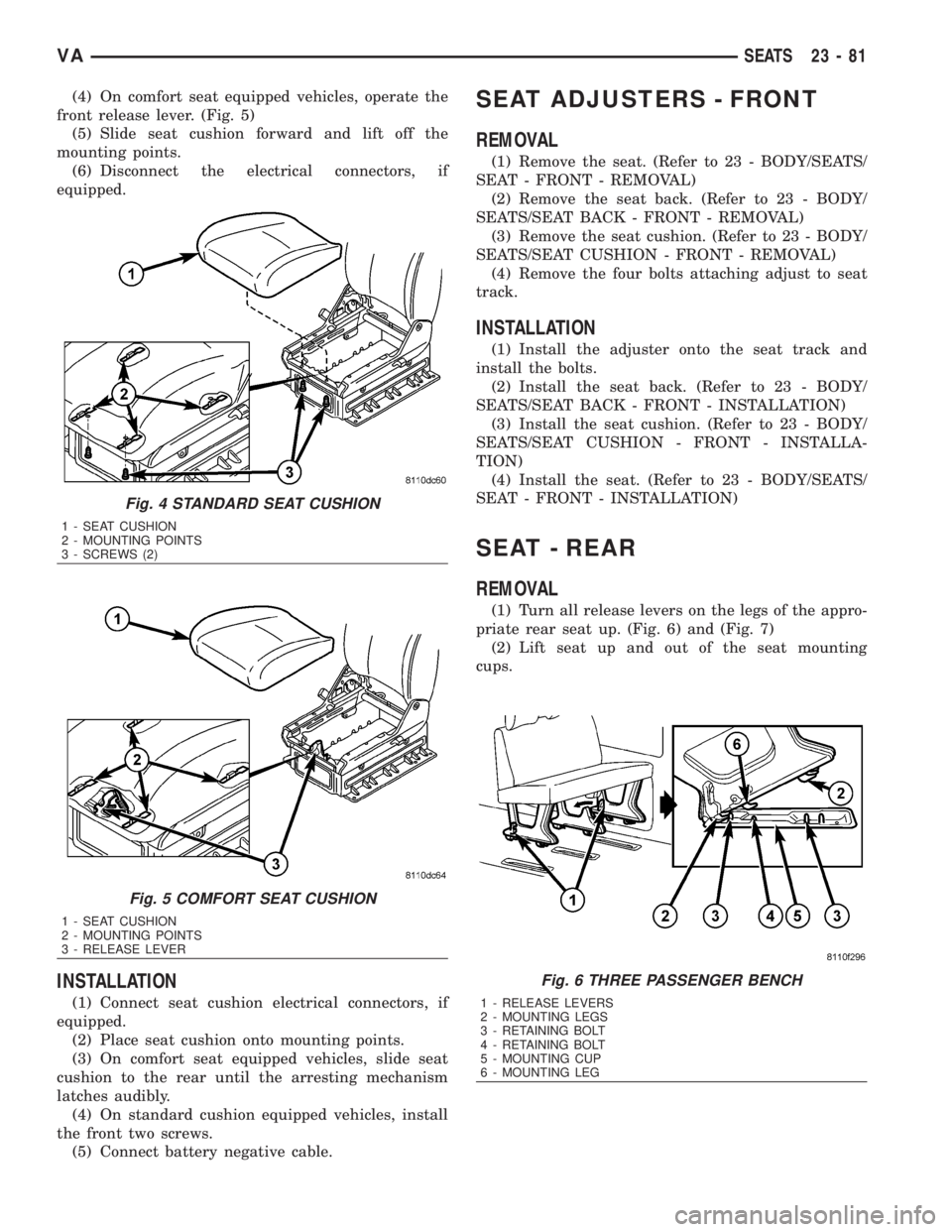
(4) On comfort seat equipped vehicles, operate the
front release lever. (Fig. 5)
(5) Slide seat cushion forward and lift off the
mounting points.
(6) Disconnect the electrical connectors, if
equipped.
INSTALLATION
(1) Connect seat cushion electrical connectors, if
equipped.
(2) Place seat cushion onto mounting points.
(3) On comfort seat equipped vehicles, slide seat
cushion to the rear until the arresting mechanism
latches audibly.
(4) On standard cushion equipped vehicles, install
the front two screws.
(5) Connect battery negative cable.
SEAT ADJUSTERS - FRONT
REMOVAL
(1) Remove the seat. (Refer to 23 - BODY/SEATS/
SEAT - FRONT - REMOVAL)
(2) Remove the seat back. (Refer to 23 - BODY/
SEATS/SEAT BACK - FRONT - REMOVAL)
(3) Remove the seat cushion. (Refer to 23 - BODY/
SEATS/SEAT CUSHION - FRONT - REMOVAL)
(4) Remove the four bolts attaching adjust to seat
track.
INSTALLATION
(1) Install the adjuster onto the seat track and
install the bolts.
(2) Install the seat back. (Refer to 23 - BODY/
SEATS/SEAT BACK - FRONT - INSTALLATION)
(3) Install the seat cushion. (Refer to 23 - BODY/
SEATS/SEAT CUSHION - FRONT - INSTALLA-
TION)
(4) Install the seat. (Refer to 23 - BODY/SEATS/
SEAT - FRONT - INSTALLATION)
SEAT - REAR
REMOVAL
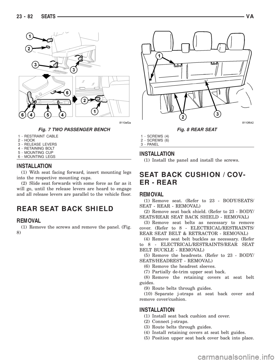
(1) Turn all release levers on the legs of the appro-
priate rear seat up. (Fig. 6) and (Fig. 7)
(2) Lift seat up and out of the seat mounting
cups.
Fig. 4 STANDARD SEAT CUSHION
1 - SEAT CUSHION
2 - MOUNTING POINTS
3 - SCREWS (2)
Fig. 5 COMFORT SEAT CUSHION
1 - SEAT CUSHION
2 - MOUNTING POINTS
3 - RELEASE LEVER
Fig. 6 THREE PASSENGER BENCH
1 - RELEASE LEVERS
2 - MOUNTING LEGS
3 - RETAINING BOLT
4 - RETAINING BOLT
5 - MOUNTING CUP
6 - MOUNTING LEG
VASEATS 23 - 81
Page 2025 of 2305
INSTALLATION
(1) With seat facing forward, insert mounting legs
into the respective mounting cups.
(2) Slide seat forwards with some force as far as it
will go, until the release levers are heard to engage
and all release levers are parallel to the vehicle floor.
REAR SEAT BACK SHIELD
REMOVAL
(1) Remove the screws and remove the panel. (Fig.
8)
INSTALLATION
(1) Install the panel and install the screws.
SEAT BACK CUSHION / COV-
ER - REAR
REMOVAL
(1) Remove seat. (Refer to 23 - BODY/SEATS/
SEAT - REAR - REMOVAL)
(2) Remove seat back shield. (Refer to 23 - BODY/
SEATS/REAR SEAT BACK SHIELD - REMOVAL)
(3) Remove seat belts as necessary to remove
cover. (Refer to 8 - ELECTRICAL/RESTRAINTS/
REAR SEAT BELT & RETRACTOR - REMOVAL)
(4) Remove seat belt buckles as necessary. (Refer
to 8 - ELECTRICAL/RESTRAINTS/REAR SEAT
BELT BUCKLE - REMOVAL)
(5) Remove the headrests. (Refer to 23 - BODY/
SEATS/HEADREST - REMOVAL)
(6) Remove the headrest sleeves.
(7) Partially de-trim upper seat back.
(8) Remove the retaining covers at seat belt
guides.
(9) Route belts through guides.
(10) Separate j-straps at seat back cover and
remove cover/cushion.
INSTALLATION
(1) Install seat back cushion and cover.
(2) Connect j-straps.
(3) Route belts through guides.
(4) Install retaining covers at seat belt guides.
(5) Position upper seat back cover back into place.
Fig. 7 TWO PASSENGER BENCH
1 - RESTRAINT CABLE
2 - HOOK
3 - RELEASE LEVERS
4 - RETAINING BOLT
5 - MOUNTING CUP
6 - MOUNTING LEGS
Fig. 8 REAR SEAT
1 - SCREWS (4)
2 - SCREWS (6)
3 - PANEL
23 - 82 SEATSVA
Page 2026 of 2305
(6) Install the headrest sleeves.
(7) Install the headrests. (Refer to 23 - BODY/
SEATS/HEADREST - INSTALLATION)
(8) Install the seat belt buckles. (Refer to 8 -
ELECTRICAL/RESTRAINTS/REAR SEAT BELT
BUCKLE - INSTALLATION)
(9) Install the seat belts. (Refer to 8 - ELECTRI-
CAL/RESTRAINTS/REAR SEAT BELT & RETRAC-
TOR - INSTALLATION)
(10) Install the seat back shield. (Refer to 23 -
BODY/SEATS/REAR SEAT BACK SHIELD -
INSTALLATION)
(11) Install seat. (Refer to 23 - BODY/SEATS/
SEAT - REAR - INSTALLATION)
SEAT CUSHION / COVER -
REAR
REMOVAL
(1) Remove seat. (Refer to 23 - BODY/SEATS/
SEAT - REAR - REMOVAL)
(2) Remove seat back shield. (Refer to 23 - BODY/
SEATS/REAR SEAT BACK SHIELD - REMOVAL)
(3) Remove the lower seat belt anchors as neces-
sary. (Refer to 8 - ELECTRICAL/RESTRAINTS/
REAR SEAT BELT & RETRACTOR - REMOVAL)
(4) Remove seat belt buckles as necessary. (Refer
to 8 - ELECTRICAL/RESTRAINTS/REAR SEAT
BELT BUCKLE - REMOVAL)
(5) Partially de-trim lower part of seat back.
(6) Separate the cushion/cover j-straps and remove
the seat cushion and cover from seat frame.
INSTALLATION
(1) Install seat cushion and cover.
(2) Connect the cover j-straps.
(3) Position seat back cover, back.
(4) Install the seat belt buckles. (Refer to 8 -
ELECTRICAL/RESTRAINTS/REAR SEAT BELT
BUCKLE - INSTALLATION)
(5) Install the seat belt anchors. (Refer to 8 -
ELECTRICAL/RESTRAINTS/REAR SEAT BELT &
RETRACTOR - INSTALLATION)
(6) Install the seat back shield. (Refer to 23 -
BODY/SEATS/REAR SEAT BACK SHIELD -
INSTALLATION)
(7) Install seat. (Refer to 23 - BODY/SEATS/SEAT
- REAR - INSTALLATION)
VASEATS 23 - 83
Page 2027 of 2305
STATIONARY GLASS
TABLE OF CONTENTS
page page
BACKLITE - BULKHEAD TRIM PANEL
REMOVAL.............................84
INSTALLATION.........................84
QUARTER WINDOW
REMOVAL.............................84
INSTALLATION.........................84WINDSHIELD
WARNING
WINDSHIELD SAFETY PRECAUTIONS.....85
REMOVAL.............................85
INSTALLATION.........................86
BACKLITE - BULKHEAD TRIM
PANEL
REMOVAL
(1) Position an assistant opposite side of the bulk-
head trim panel to receive the glass and weatherstrip
seal.
(2) Start at an upper corner and separate the seal
from the window opening. Push the glass and seal
outward from the window opening. Remove the glass
and seal.
(3) Remove seal from glass if necessary.
(4) Clean the window opening.
INSTALLATION
(1) Install the weatherstrip seal on the window
glass. Verify that the glass is seated in the groove
around the edge of the seal.
(2) Insert an installation cord in the weatherstrip
seal inner groove.
NOTE: Use mineral spirits as a lubricant to aid seal
installation in the window opening.
(3) Position the glass and seal in the trim panel
opening.
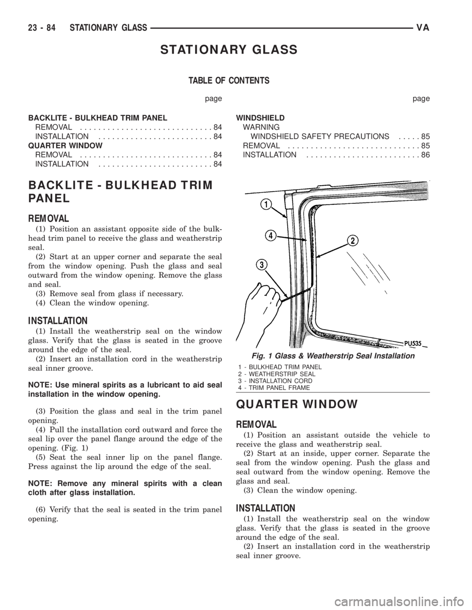
(4) Pull the installation cord outward and force the
seal lip over the panel flange around the edge of the
opening. (Fig. 1)
(5) Seat the seal inner lip on the panel flange.
Press against the lip around the edge of the seal.
NOTE: Remove any mineral spirits with a clean
cloth after glass installation.
(6) Verify that the seal is seated in the trim panel
opening.
QUARTER WINDOW
REMOVAL
(1) Position an assistant outside the vehicle to
receive the glass and weatherstrip seal.
(2) Start at an inside, upper corner. Separate the
seal from the window opening. Push the glass and
seal outward from the window opening. Remove the
glass and seal.
(3) Clean the window opening.
INSTALLATION
(1) Install the weatherstrip seal on the window
glass. Verify that the glass is seated in the groove
around the edge of the seal.
(2) Insert an installation cord in the weatherstrip
seal inner groove.
Fig. 1 Glass & Weatherstrip Seal Installation
1 - BULKHEAD TRIM PANEL
2 - WEATHERSTRIP SEAL
3 - INSTALLATION CORD
4 - TRIM PANEL FRAME
23 - 84 STATIONARY GLASSVA
Page 2028 of 2305
NOTE: Use mineral spirits as a lubricant to aid seal
installation in the window opening.
(3) Position the glass and seal in the window open-
ing.
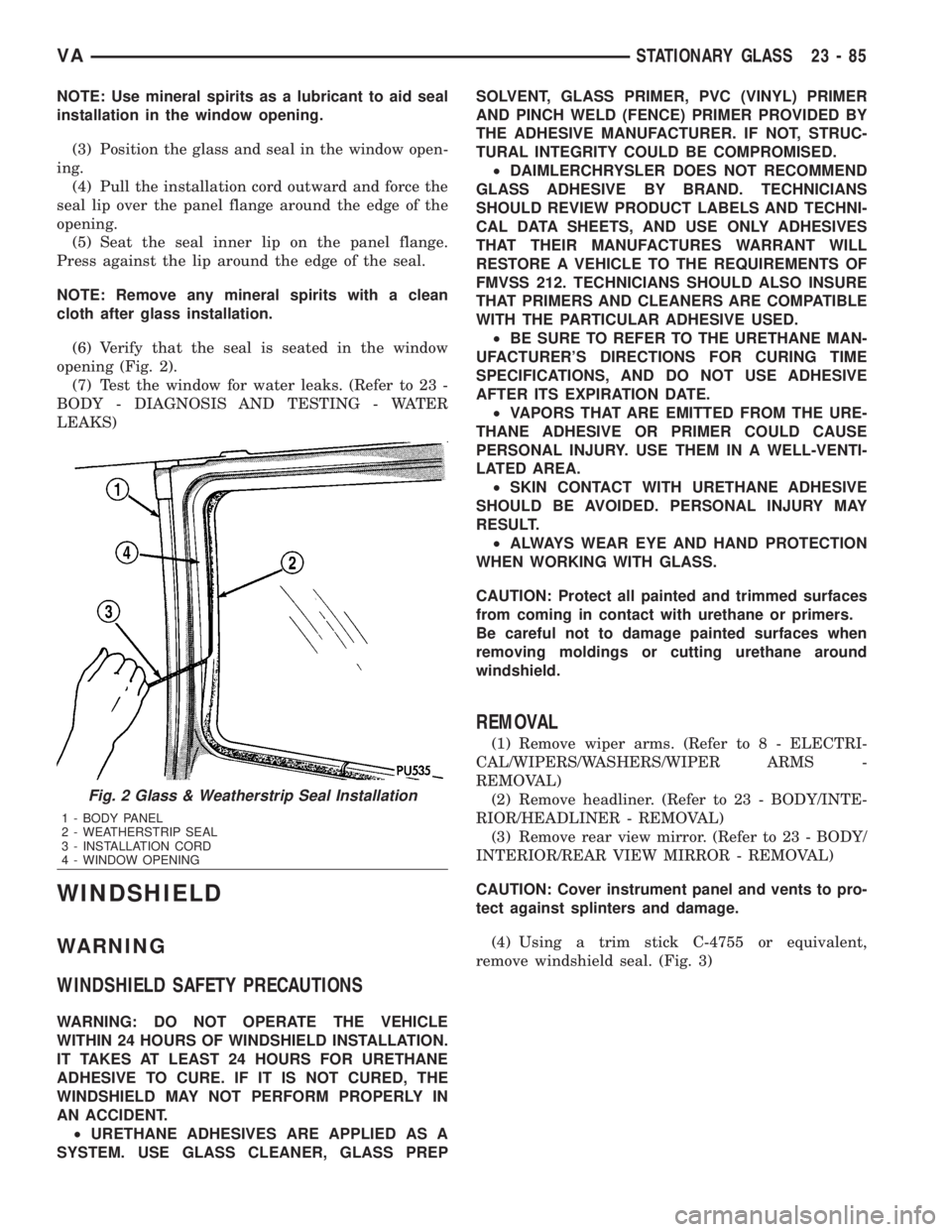
(4) Pull the installation cord outward and force the
seal lip over the panel flange around the edge of the
opening.
(5) Seat the seal inner lip on the panel flange.
Press against the lip around the edge of the seal.
NOTE: Remove any mineral spirits with a clean
cloth after glass installation.
(6) Verify that the seal is seated in the window
opening (Fig. 2).
(7) Test the window for water leaks. (Refer to 23 -
BODY - DIAGNOSIS AND TESTING - WATER
LEAKS)
WINDSHIELD
WARNING
WINDSHIELD SAFETY PRECAUTIONS
WARNING: DO NOT OPERATE THE VEHICLE
WITHIN 24 HOURS OF WINDSHIELD INSTALLATION.
IT TAKES AT LEAST 24 HOURS FOR URETHANE
ADHESIVE TO CURE. IF IT IS NOT CURED, THE
WINDSHIELD MAY NOT PERFORM PROPERLY IN
AN ACCIDENT.
²URETHANE ADHESIVES ARE APPLIED AS A
SYSTEM. USE GLASS CLEANER, GLASS PREPSOLVENT, GLASS PRIMER, PVC (VINYL) PRIMER
AND PINCH WELD (FENCE) PRIMER PROVIDED BY
THE ADHESIVE MANUFACTURER. IF NOT, STRUC-
TURAL INTEGRITY COULD BE COMPROMISED.
²DAIMLERCHRYSLER DOES NOT RECOMMEND
GLASS ADHESIVE BY BRAND. TECHNICIANS
SHOULD REVIEW PRODUCT LABELS AND TECHNI-
CAL DATA SHEETS, AND USE ONLY ADHESIVES
THAT THEIR MANUFACTURES WARRANT WILL
RESTORE A VEHICLE TO THE REQUIREMENTS OF
FMVSS 212. TECHNICIANS SHOULD ALSO INSURE
THAT PRIMERS AND CLEANERS ARE COMPATIBLE
WITH THE PARTICULAR ADHESIVE USED.
²BE SURE TO REFER TO THE URETHANE MAN-
UFACTURER'S DIRECTIONS FOR CURING TIME
SPECIFICATIONS, AND DO NOT USE ADHESIVE
AFTER ITS EXPIRATION DATE.
²VAPORS THAT ARE EMITTED FROM THE URE-
THANE ADHESIVE OR PRIMER COULD CAUSE
PERSONAL INJURY. USE THEM IN A WELL-VENTI-
LATED AREA.
²SKIN CONTACT WITH URETHANE ADHESIVE
SHOULD BE AVOIDED. PERSONAL INJURY MAY
RESULT.
²ALWAYS WEAR EYE AND HAND PROTECTION
WHEN WORKING WITH GLASS.
CAUTION: Protect all painted and trimmed surfaces
from coming in contact with urethane or primers.
Be careful not to damage painted surfaces when
removing moldings or cutting urethane around
windshield.
REMOVAL
(1) Remove wiper arms. (Refer to 8 - ELECTRI-
CAL/WIPERS/WASHERS/WIPER ARMS -
REMOVAL)
(2) Remove headliner. (Refer to 23 - BODY/INTE-
RIOR/HEADLINER - REMOVAL)
(3) Remove rear view mirror. (Refer to 23 - BODY/
INTERIOR/REAR VIEW MIRROR - REMOVAL)
CAUTION: Cover instrument panel and vents to pro-
tect against splinters and damage.
(4) Using a trim stick C-4755 or equivalent,
remove windshield seal. (Fig. 3)
Fig. 2 Glass & Weatherstrip Seal Installation
1 - BODY PANEL
2 - WEATHERSTRIP SEAL
3 - INSTALLATION CORD
4 - WINDOW OPENING
VASTATIONARY GLASS 23 - 85
Page 2029 of 2305
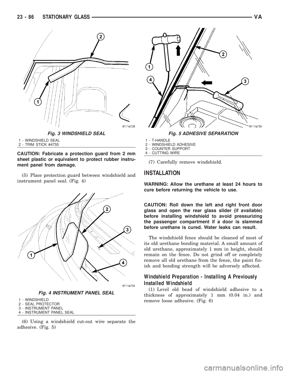
CAUTION: Fabricate a protection guard from 2 mm
sheet plastic or equivalent to protect rubber instru-
ment panel from damage.
(5) Place protection guard between windshield and
instrument panel seal. (Fig. 4)
(6) Using a windshield cut-out wire separate the
adhesive. (Fig. 5)(7) Carefully remove windshield.
INSTALLATION
WARNING: Allow the urethane at least 24 hours to
cure before returning the vehicle to use.
CAUTION: Roll down the left and right front door
glass and open the rear glass slider (if available)
before installing windshield to avoid pressurizing
the passenger compartment if a door is slammed
before urethane is cured. Water leaks can result.
The windshield fence should be cleaned of most of
its old urethane bonding material. A small amount of
old urethane, approximately 1 mm in height, should
remain on the fence. Do not grind off or completely
remove all old urethane from the fence, the paint fin-
ish and bonding strength will be adversely affected.
Windshield Preparation - Installing A Previously
Installed Windshield
(1) Level old bead of windshield adhesive to a
thickness of approximately 1 mm (0.04 in.) and
remove loose adhesive. (Fig. 6)
Fig. 3 WINDSHIELD SEAL
1 - WINDSHIELD SEAL
2 - TRIM STICK #4755
Fig. 4 INSTRUMENT PANEL SEAL
1 - WINDSHIELD
2 - SEAL PROTECTOR
3 - INSTRUMENT PANEL
4 - INSTRUMENT PANEL SEAL
Fig. 5 ADHESIVE SEPARATION
1 - T-HANDLE
2 - WINDSHIELD ADHESIVE
3 - COUNTER SUPPORT
4 - CUTTING WIRE
23 - 86 STATIONARY GLASSVA
Page 2030 of 2305
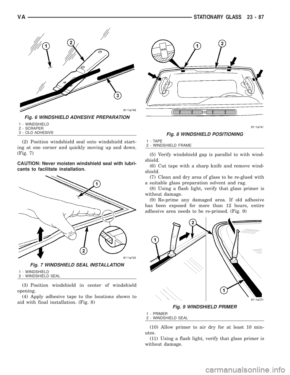
(2) Position windshield seal onto windshield start-
ing at one corner and quickly moving up and down.
(Fig. 7)
CAUTION: Never moisten windshield seal with lubri-
cants to facilitate installation.
(3) Position windshield in center of windshield
opening.
(4) Apply adhesive tape to the locations shown to
aid with final installation. (Fig. 8)(5) Verify windshield gap is parallel to with wind-
shield.
(6) Cut tape with a sharp knife and remove wind-
shield.
(7) Clean and dry area of glass to be re-glued with
a suitable glass preparation solvent and rag.
(8) Using a flash light, verify that glass primer is
without damage.
(9) Re-prime any damaged area. If old adhesive
has been exposed for more than 12 hours, entire
adhesive area needs to be re-primed. (Fig. 9)
(10) Allow primer to air dry for at least 10 min-
utes.
(11) Using a flash light, verify that glass primer is
without damage.
Fig. 6 WINDSHIELD ADHESIVE PREPARATION
1 - WINDSHIELD
2 - SCRAPER
3 - OLD ADHESIVE
Fig. 7 WINDSHIELD SEAL INSTALLATION
1 - WINDSHIELD
2 - WINDSHIELD SEAL
Fig. 8 WINDSHIELD POSITIONING
1 - TAPE
2 - WINDSHIELD FRAME
Fig. 9 WINDSHIELD PRIMER
1 - PRIMER
2 - WINDSHIELD SEAL
VASTATIONARY GLASS 23 - 87