MERCEDES-BENZ SPRINTER 2011 MY11 Operator’s Manual
Manufacturer: MERCEDES-BENZ, Model Year: 2011, Model line: SPRINTER, Model: MERCEDES-BENZ SPRINTER 2011Pages: 292, PDF Size: 6.75 MB
Page 241 of 292
X
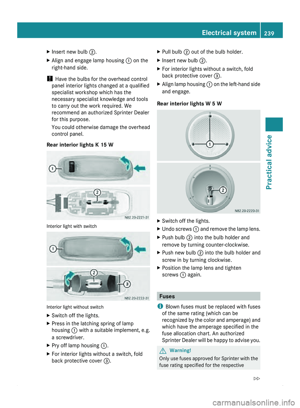
Insert new bulb 0047.
X Align and engage lamp housing 0046 on the
right-hand side.
! Have the bulbs for the overhead control
panel interior lights changed at a qualified
specialist workshop which has the
necessary specialist knowledge and tools
to carry out the work required. We
recommend an authorized Sprinter Dealer
for this purpose.
You could
otherwise
damage the overhead
control panel.
Rear interior lights K 15 W Interior light with switch
Interior light without switch
X
Switch off the lights.
X Press in the latching spring of lamp
housing 0046 with a
suitable implement, e.g.
a screwdriver.
X Pry off lamp housing 0046.
X For interior lights without a switch, fold
back protective cover 008A. X
Pull bulb 0047 out of the bulb holder.
X Insert new bulb 0047.
X For interior lights without a switch, fold
back protective cover 008A.
X Align lamp housing 0046 on the
left-hand side
and engage.
Rear interior lights W 5 W X
Switch off the lights.
X Undo screws 0046
and remove
the lamp lens.
X Push bulb 0047 into the bulb holder and
remove by turning counter-clockwise.
X Push new bulb 0047 into the bulb holder and
screw in by turning clockwise.
X Position the lamp lens and tighten
screws 0046 again. Fuses
i Blown fuses must be replaced with fuses
of the same rating (which can be
recognized by the
color and amperage) and
which have the amperage specified in the
fuse allocation chart. An authorized
Sprinter Dealer will be happy to advise you. G
Warning!
Only use fuses approved for Sprinter with the
fuse rating specified for the respective Electrical system
239
Practical advice
Z
Page 242 of 292
systems. Do not repair or bypass defective
fuses. A fire may otherwise result through
overload. Have the problem assessed and
resolved only at a qualified specialist
workshop, e.g.
an
authorized Sprinter Dealer.
The fuses and relays for the standard
equipment are located in the main fuse box
in the footwell on the left-hand side of the
vehicle.
Additional fuses and relays for the items of
optional equipment are located in the fuse
box under the driver's seat.
i The fuse allocation chart for the fuse
boxes is in the vehicle document wallet in
the glove box and shows all numbered
fuses.
X Switch off the ignition and the electrical
consumers before changing a fuse.
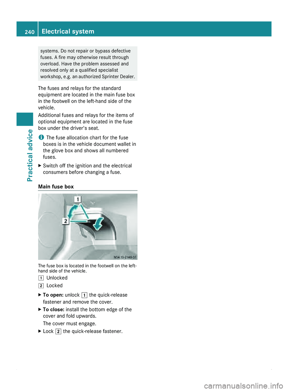
Main fuse box The fuse box is located in the footwell on the left-
hand side of the vehicle.
004A
Unlocked
004B Locked
X To open: unlock
004A the quick-release
fastener and remove the cover.
X To close: install the bottom edge of the
cover and fold upwards.
The cover must engage.
X Lock 004B the quick-release fastener.240
Electrical system
Practical advice
Page 243 of 292
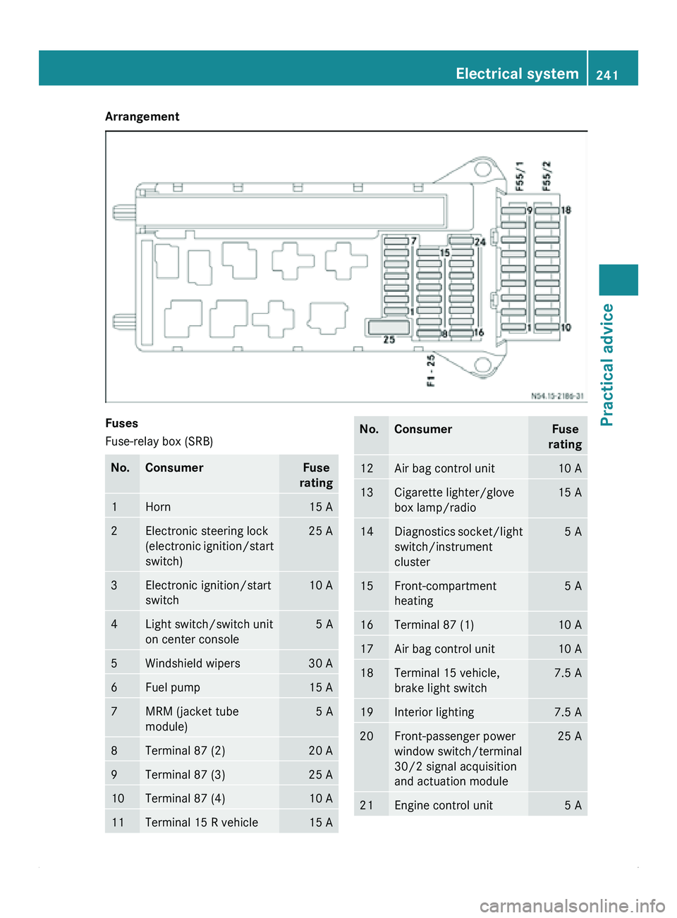
Arrangement
Fuses
Fuse-relay box (SRB)
No. Consumer Fuse
rating 1 Horn 15 A
2 Electronic steering lock
(electronic ignition/start
switch) 25 A
3 Electronic ignition/start
switch 10 A
4 Light switch/switch unit
on center console 5 A
5 Windshield wipers 30 A
6 Fuel pump 15 A
7 MRM (jacket tube
module) 5 A
8 Terminal 87 (2) 20 A
9 Terminal 87 (3) 25 A
10 Terminal 87 (4) 10 A
11 Terminal 15 R vehicle 15 A No. Consumer Fuse
rating 12 Air bag control unit 10 A
13 Cigarette lighter/glove
box lamp/radio 15 A
14 Diagnostics socket/light
switch/instrument
cluster 5 A
15 Front-compartment
heating 5 A
16 Terminal 87 (1) 10 A
17 Air bag control unit 10 A
18 Terminal 15 vehicle,
brake light switch 7.5 A
19 Interior lighting 7.5 A
20 Front-passenger power
window switch/terminal
30/2 signal acquisition
and actuation module 25 A
21 Engine control unit 5 AElectrical system
241Practical advice Z
Page 244 of 292
No. Consumer Fuse
rating 22 Brake system (ABS) 5 A
23 Starter motor 20 A
24 Engine components 10 A
25 12 V socket in the center
console 25 A
Fuse block F55/1
No. Consumer Fuse
rating 1 Left door control unit 25 A
2 Diagnostics socket 10 A
3 Brake system (valves) 25 A
4 Brake system (delivery
pump) 40 A
5 Terminal 87 (5) engine 7.5/10 A
6 Terminal 87 (6) engine 7.5/10 A
7 Headlamp cleaning
system 30 A
8 Anti-theft alarm system
(ATA) 15 A
9 Additional turn signal
module 10 A
Fuse block F55/2
No. Consumer Fuse
rating 10 Radio 15 A
11 Mobile phone 7.5 A
12 Blower, front/auxiliary
heating blower setting 1 30 A
13 Auxiliary heating digital
timer, radio receiver/
basic wiring DIN-
slot 7.5 A No. Consumer Fuse
rating 14 Seat heating 30 A
15 Unassigned —
16 Heating, rear-
compartment heating/
front-compartment air
conditioning/CD player 10 A
17 Motion detector/
convenience lighting 10 A
18 Rear-compartment air-
conditioning system 7.5 A
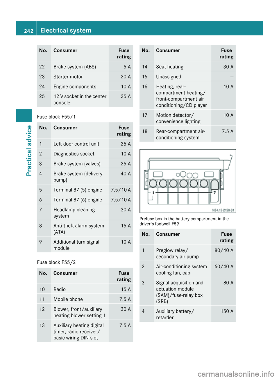
Prefuse box in the battery compartment in the
driver's footwell F59
No. Consumer Fuse
rating 1 Preglow relay/
secondary air pump 80/40 A
2 Air-conditioning system
cooling fan, cab 60/40 A
3 Signal acquisition and
actuation module
(SAM)/fuse-relay box
(SRB) 80 A
4 Auxiliary battery/
retarder 150 A242
Electrical systemPractical advice
Page 245 of 292
No. Consumer Fuse
rating 5 Terminal 30 fuse box,
signal acquisition and
actuation module
(SAM)/fuse-relay box
(SRB) 150 A
6 Connection point on the
base of the seat Bridge
7 PTC heater booster 150 A
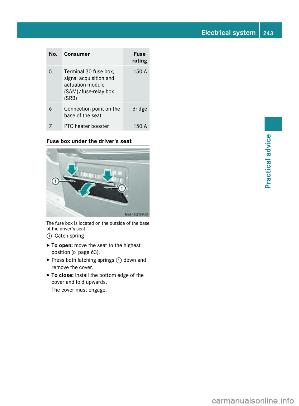
Fuse box under the driver's seat
The fuse box is located on the outside of the base
of the driver's seat.
0046
Catch spring
X To open: move the seat to the highest
position (Y page 63).
X Press both latching springs 0046 down and
remove the cover.
X To close: install the bottom edge of the
cover and fold upwards.
The cover must engage. Electrical system
243Practical advice Z
Page 246 of 292
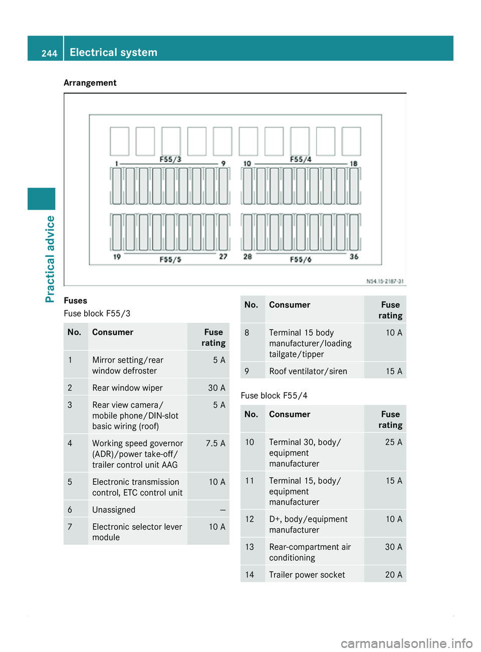
Arrangement
Fuses
Fuse block F55/3
No. Consumer Fuse
rating 1 Mirror setting/rear
window defroster 5 A
2 Rear window wiper 30 A
3 Rear view camera/
mobile phone/DIN-slot
basic wiring (roof) 5 A
4 Working speed governor
(ADR)/power take-off/
trailer control unit AAG 7.5 A
5 Electronic transmission
control, ETC control unit 10 A
6 Unassigned —
7 Electronic selector lever
module 10 A No. Consumer Fuse
rating 8 Terminal 15 body
manufacturer/loading
tailgate/tipper 10 A
9 Roof ventilator/siren 15 A
Fuse block F55/4
No. Consumer Fuse
rating 10 Terminal 30, body/
equipment
manufacturer 25 A
11 Terminal 15, body/
equipment
manufacturer 15 A
12 D+, body/equipment
manufacturer 10 A
13 Rear-compartment air
conditioning 30 A
14 Trailer power socket 20 A244
Electrical systemPractical advice
Page 247 of 292
No. Consumer Fuse
rating 15 Trailer recognition unit 25 A
16 Tire pressure monitor/
PARKTRONIC 7.5 A
17 PSM control unit 25 A
18 PSM control unit 25 A
Fuse block F55/5
No. Consumer Fuse
rating 19 Overhead control panel 5 A
20 Perimeter lamp 7.5 A
21 Rear window defroster 1 30 A
22 Rear window defroster 2 15 A
23 12 V socket rear left,
cargo compartment/
passenger
compartment/non-MB
body electrics 15 A
24 12 V socket under the
base of driver's seat 15 A
25 12 V socket rear right,
cargo compartment/
passenger compartment 15 A
26 Auxiliary heating 25 A
27 Heater booster system 25 A
Fuse block F55/6
No. Consumer Fuse
rating 28 Exhaust gas
aftertreatment – SCR
10
control unit 10 A
29 Unassigned — No. Consumer Fuse
rating 30 Brake booster 30 A
31 Rear-compartment
heating blower/sliding
door closing assistance,
left 30/15 A
32 Exhaust gas
aftertreatment – SCR
10
relay power supply 10 A
33 Sliding door closing
assistance, right 15 A
34 Exhaust gas
aftertreatment – SCR
10
heater 1 tank 15 A
35 Exhaust gas
aftertreatment – SCR
10
heater 2 hose 15 A
36 Exhaust gas
aftertreatment – SCR
10
heater 3 delivery pump 10 A
Batteries for the remote control
Notes on changing the batteries
G
Warning!
Batteries are toxic and contain caustic
substances. For this reason, keep batteries
out of the reach of children.
If a battery
has been swallowed, visit a doctor
immediately.
0040Environmental note Batteries contain toxic substances.
It is illegal to dispose of them with
household
waste. Batteries
must be
collected separately and be
10 Selective Catalytic Reduction. Batteries for the remote control
245
Practical advice Z
Page 248 of 292
recycled in an environmentally
responsible manner.
Dispose of old batteries in an
environmentally responsible
manner. Take discharged batteries
to a qualified specialist workshop,
e.g. an authorized Sprinter Dealer,
or to a special collection point for
old batteries.
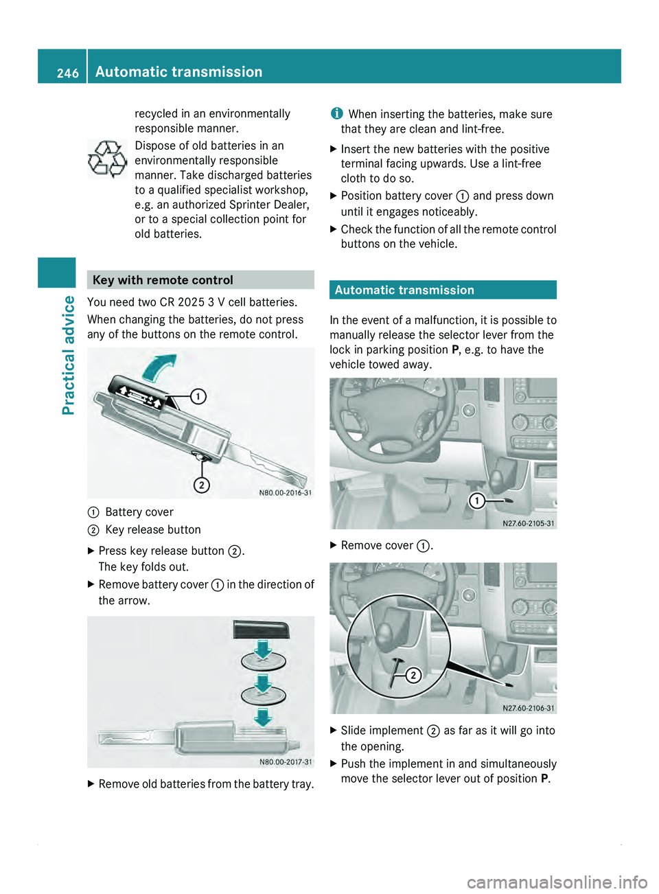
Key with remote control
You need two CR 2025 3 V cell batteries.
When changing the batteries, do not press
any of the buttons on the remote control. 0046
Battery cover
0047 Key release button
X Press key release button 0047.
The key folds out.
X Remove battery cover 0046 in
the direction of
the arrow. X
Remove old batteries from the battery tray. i
When inserting the batteries, make sure
that they are clean and lint-free.
X Insert the new batteries with the positive
terminal facing upwards. Use a lint-free
cloth to do so.
X Position battery cover 0046 and press down
until it engages noticeably.
X Check the function of all the remote control
buttons on the vehicle. Automatic transmission
In the event
of a malfunction, it is possible to
manually release the selector lever from the
lock in parking position P, e.g. to have the
vehicle towed away. X
Remove cover 0046. X
Slide implement 0047 as far as it will go into
the opening.
X Push the implement in and simultaneously
move the selector lever out of position P.246
Automatic transmission
Practical advice
Page 249 of 292
X
Remove implement 0047.
X Refit cover 0046. Jump starting, tow-starting and
towing away
Jump-starting
General notes If the vehicle battery is flat, the engine can be
started from another vehicle using jumper
cables. For this purpose, the vehicle has a
jump-starting connection point in the engine
compartment.
The additional battery in the engine
compartment is
not
suitable for jump-starting
operations. If your vehicle requires jump-
starting, or if you use it to jump-start another
vehicle, use the jump-starting connection
point in the engine compartment. G
Warning
Explosive oxyhydrogen is produced when
batteries are being
charged. When working on
batteries, always make sure that the work
area is well ventilated.
Keep flames and naked lights away from the
battery, and do not smoke.
Prevent the creation of sparks (e.g. when
disconnecting the batteries). Sparks can
ignite the oxyhydrogen gas and cause the
batteries to explode. You and others could be
seriously injured. G
Warning
Due to the gases which escape from batteries,
there is a risk of acid burns when jump-
starting a vehicle.
Do not lean over the battery
while the engine is being jump-started.
! Avoid repeated and lengthy starting
attempts.
Do not use a rapid-charging device to start
the engine. When jump-starting, observe the following
points:
R
jump-starting must only be performed
when the engine and catalytic converter
are cold.
R do not start the engine if the battery is
frozen. Let the battery thaw first.
R when jump-starting, use
only batteries with
the same nominal voltage and a similar
capacity.
R only use jump leads protected against
polarity reversal, with adequate cross-
section and with insulated battery terminal
clamps.
X Make sure that the two vehicles do not
touch.
X Apply the parking brake.
X Move the selector lever of the automatic
transmission to position P.
X Switch off all electrical consumers.
X Switch on the battery isolating switch
(Y page 87).
X Remove the key from the ignition lock.
X Open the hood (Y page 168).
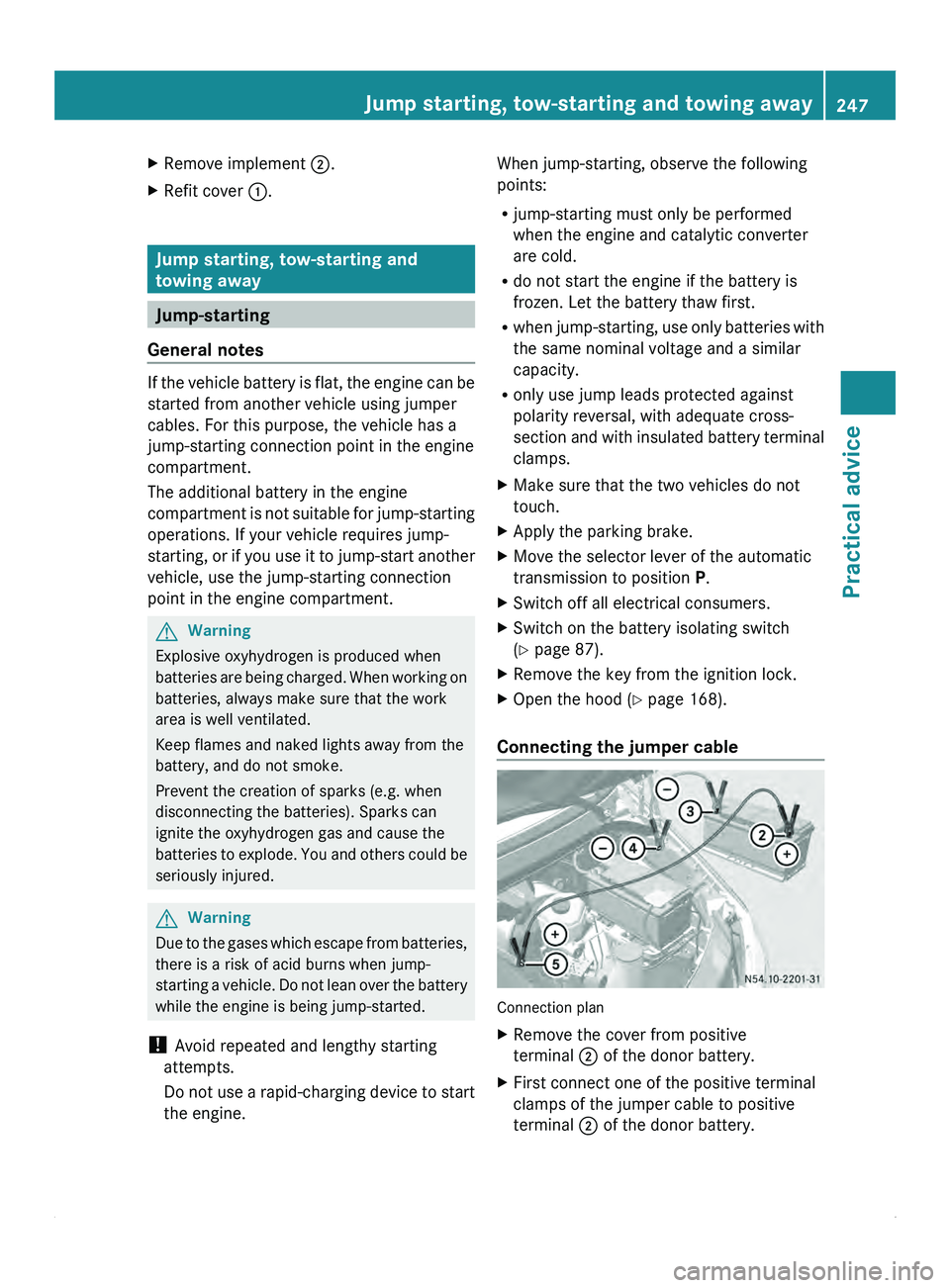
Connecting the jumper cable Connection plan
X
Remove the cover from positive
terminal 0047 of the donor battery.
X First connect one of the positive terminal
clamps of the jumper cable to positive
terminal 0047 of the donor battery. Jump starting, tow-starting and towing away
247
Practical advice Z
Page 250 of 292
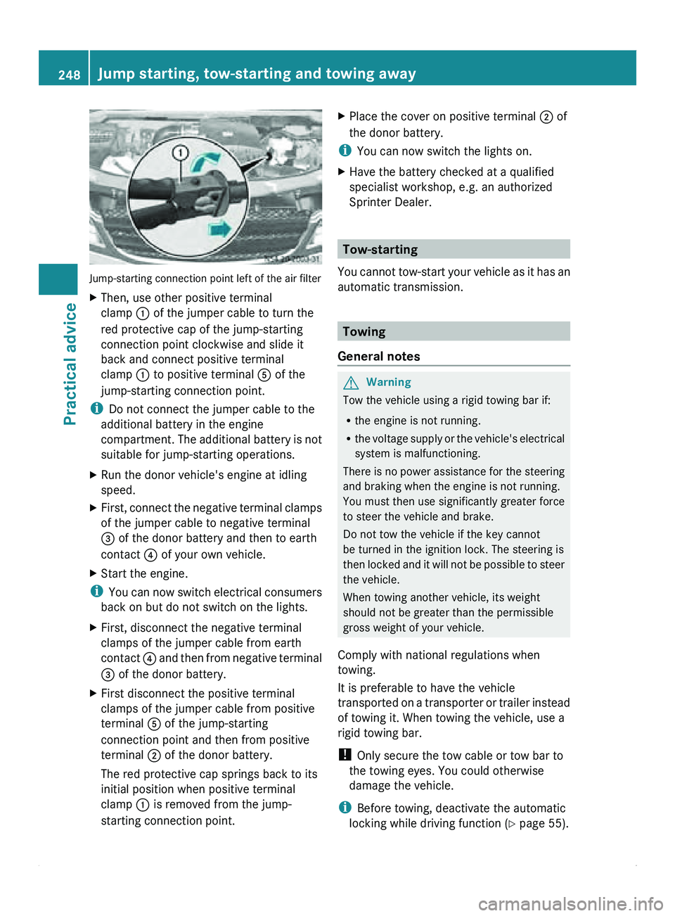
Jump-starting connection point left of the air filter
X
Then, use other positive terminal
clamp 0046 of the jumper cable to turn the
red protective cap of the jump-starting
connection point clockwise and slide it
back and connect positive terminal
clamp 0046 to positive terminal 0086 of the
jump-starting connection point.
i Do not connect the jumper cable to the
additional battery in the engine
compartment. The
additional
battery is not
suitable for jump-starting operations.
X Run the donor vehicle's engine at idling
speed.
X First, connect the negative terminal clamps
of the jumper cable to negative terminal
008A of the donor battery and then to earth
contact 0088 of your own vehicle.
X Start the engine.
i You can
now
switch electrical consumers
back on but do not switch on the lights.
X First, disconnect the negative terminal
clamps of the jumper cable from earth
contact 0088 and then
from negative terminal
008A of the donor battery.
X First disconnect the positive terminal
clamps of the jumper cable from positive
terminal 0086 of the jump-starting
connection point and then from positive
terminal 0047 of the donor battery.
The red protective cap springs back to its
initial position when positive terminal
clamp 0046 is removed from the jump-
starting connection point. X
Place the cover on positive terminal 0047 of
the donor battery.
i You can now switch the lights on.
X Have the battery checked at a qualified
specialist workshop, e.g. an authorized
Sprinter Dealer. Tow-starting
You cannot tow-start
your vehicle as it has an
automatic transmission. Towing
General notes G
Warning
Tow the vehicle using a rigid towing bar if:
R the engine is not running.
R the voltage supply
or the vehicle's electrical
system is malfunctioning.
There is no power assistance for the steering
and braking when the engine is not running.
You must then use significantly greater force
to steer the vehicle and brake.
Do not tow the vehicle if the key cannot
be turned in the ignition lock. The steering is
then locked and it will not be possible to steer
the vehicle.
When towing another vehicle, its weight
should not be greater than the permissible
gross weight of your vehicle.
Comply with national regulations when
towing.
It is preferable to have the vehicle
transported on a transporter or trailer instead
of towing it. When towing the vehicle, use a
rigid towing bar.
! Only secure the tow cable or tow bar to
the towing eyes. You could otherwise
damage the vehicle.
i Before towing, deactivate the automatic
locking while driving function (Y page 55). 248
Jump starting, tow-starting and towing away
Practical advice