lights MERCEDES-BENZ SPRINTER 2012 MY12 Operator’s Manual
[x] Cancel search | Manufacturer: MERCEDES-BENZ, Model Year: 2012, Model line: SPRINTER, Model: MERCEDES-BENZ SPRINTER 2012Pages: 292, PDF Size: 6.75 MB
Page 237 of 292
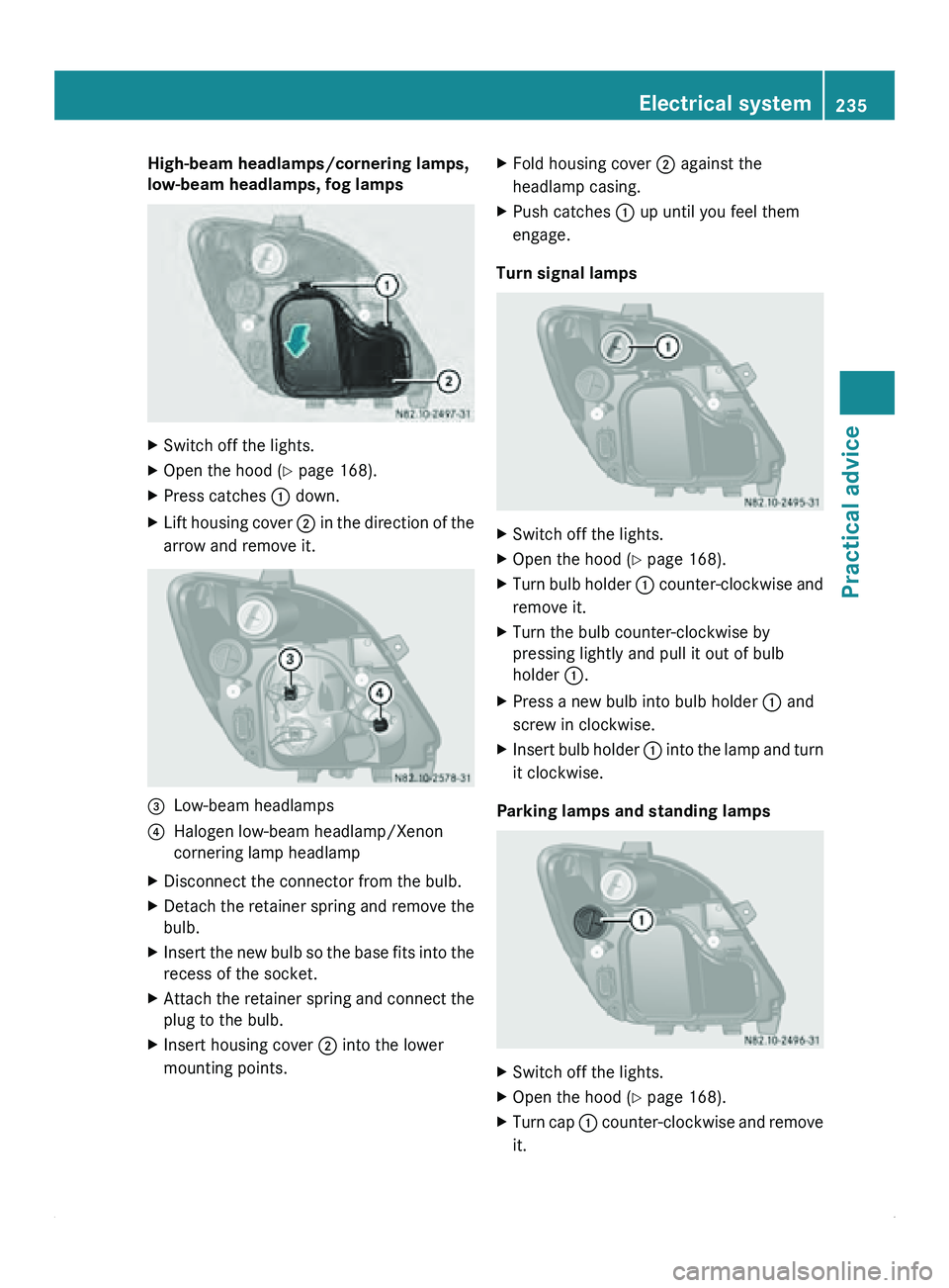
High-beam headlamps/cornering lamps,
low-beam headlamps, fog lamps
X
Switch off the lights.
X Open the hood (Y page 168).
X Press catches 0046 down.
X Lift housing cover 0047 in the direction of the
arrow and remove it. 008A
Low-beam headlamps
0088 Halogen low-beam headlamp/Xenon
cornering lamp headlamp
X Disconnect the connector from the bulb.
X Detach the retainer spring and remove the
bulb.
X Insert the new bulb so the base fits into the
recess of the socket.
X Attach the retainer spring and connect the
plug to the bulb.
X Insert housing cover 0047 into the lower
mounting points. X
Fold housing cover 0047 against the
headlamp casing.
X Push catches 0046 up until you feel them
engage.
Turn signal lamps X
Switch off the lights.
X Open the hood (Y page 168).
X Turn bulb holder 0046 counter-clockwise and
remove it.
X Turn the bulb counter-clockwise by
pressing lightly and pull it out of bulb
holder 0046
.
X Press a new bulb into bulb holder 0046 and
screw in clockwise.
X Insert bulb holder 0046 into the
lamp and turn
it clockwise.
Parking lamps and standing lamps X
Switch off the lights.
X Open the hood (Y page 168).
X Turn cap 0046 counter-clockwise and remove
it. Electrical system
235
Practical advice Z
Page 238 of 292
X
Pull out the bulb holder with the bulb.
X Pull the bulb out of the bulb holder.
X Press a new bulb into the bulb holder.
X Insert the bulb holder into the reflector.
X Replace cap 0046 and turn it clockwise to the
stop.
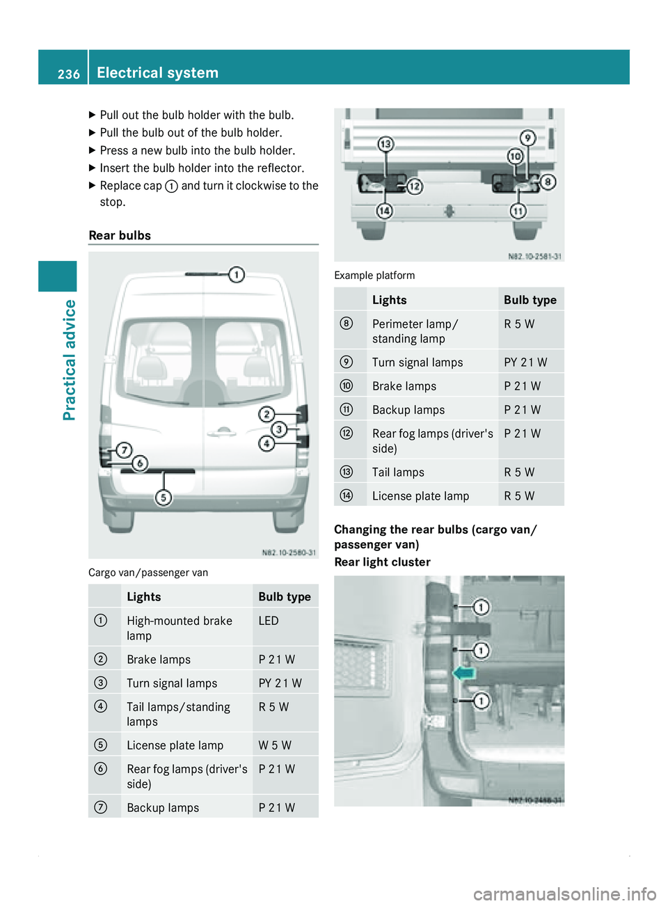
Rear bulbs Cargo van/passenger van
Lights Bulb type
0046
High-mounted brake
lamp LED
0047
Brake lamps P 21 W
008A
Turn signal lamps PY 21 W
0088
Tail lamps/standing
lamps R 5 W
0086
License plate lamp W 5 W
0087
Rear fog lamps (driver's
side) P 21 W
006E
Backup lamps P 21 W Example platform
Lights Bulb type
006F
Perimeter lamp/
standing lamp R 5 W
0070
Turn signal lamps PY 21 W
0071
Brake lamps P 21 W
0072
Backup lamps P 21 W
0073
Rear fog lamps (driver's
side) P 21 W
0074
Tail lamps R 5 W
0075
License plate lamp R 5 W
Changing the rear bulbs (cargo van/
passenger van)
Rear light cluster236
Electrical system
Practical advice
Page 239 of 292
X
Switch off the lights.
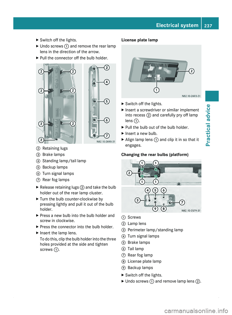
X Undo screws 0046 and remove the rear lamp
lens in the direction of the arrow.
X Pull the connector off the bulb holder. 0047
Retaining lugs
008A Brake lamps
0088 Standing lamp/tail lamp
0086 Backup lamps
0087 Turn signal lamps
006E Rear fog lamps
X Release retaining lugs 0047 and
take
the bulb
holder out of the rear lamp cluster.
X Turn the bulb counter-clockwise by
pressing lightly and pull it out of the bulb
holder.
X Press a new bulb into the bulb holder and
screw in clockwise.
X Press the connector into the bulb holder.
X Insert the lamp lens.
To do this,
clip the bulb holder into the three
holes provided at the side and tighten
screws 0046. License plate lamp
X
Switch off the lights.
X Insert a screwdriver or similar implement
into recess 0047 and carefully pry off lamp
lens 0046.
X Pull the bulb out of the bulb holder.
X Insert a new bulb.
X Align lamp lens 0046 and clip it in so that it
engages.
Changing the rear bulbs (platform) 0046
Screws
0047 Lamp lens
008A Perimeter lamp/standing lamp
0088 Turn signal lamps
0086 Brake lamps
0087 Tail lamp
006E Rear fog lamp
006F License plate lamp
0070 Backup lamps
X Switch off the lights.
X Undo screws 0046 and
remove
lamp lens 0047. Electrical system
237
Practical advice Z
Page 240 of 292
X
Turn the bulb counter-clockwise by
pressing lightly and pull it out of the bulb
holder.
X Push a new bulb into the bulb holder and
screw in clockwise.
X Position lamp lens 0047 and tighten
screws 0046 again.
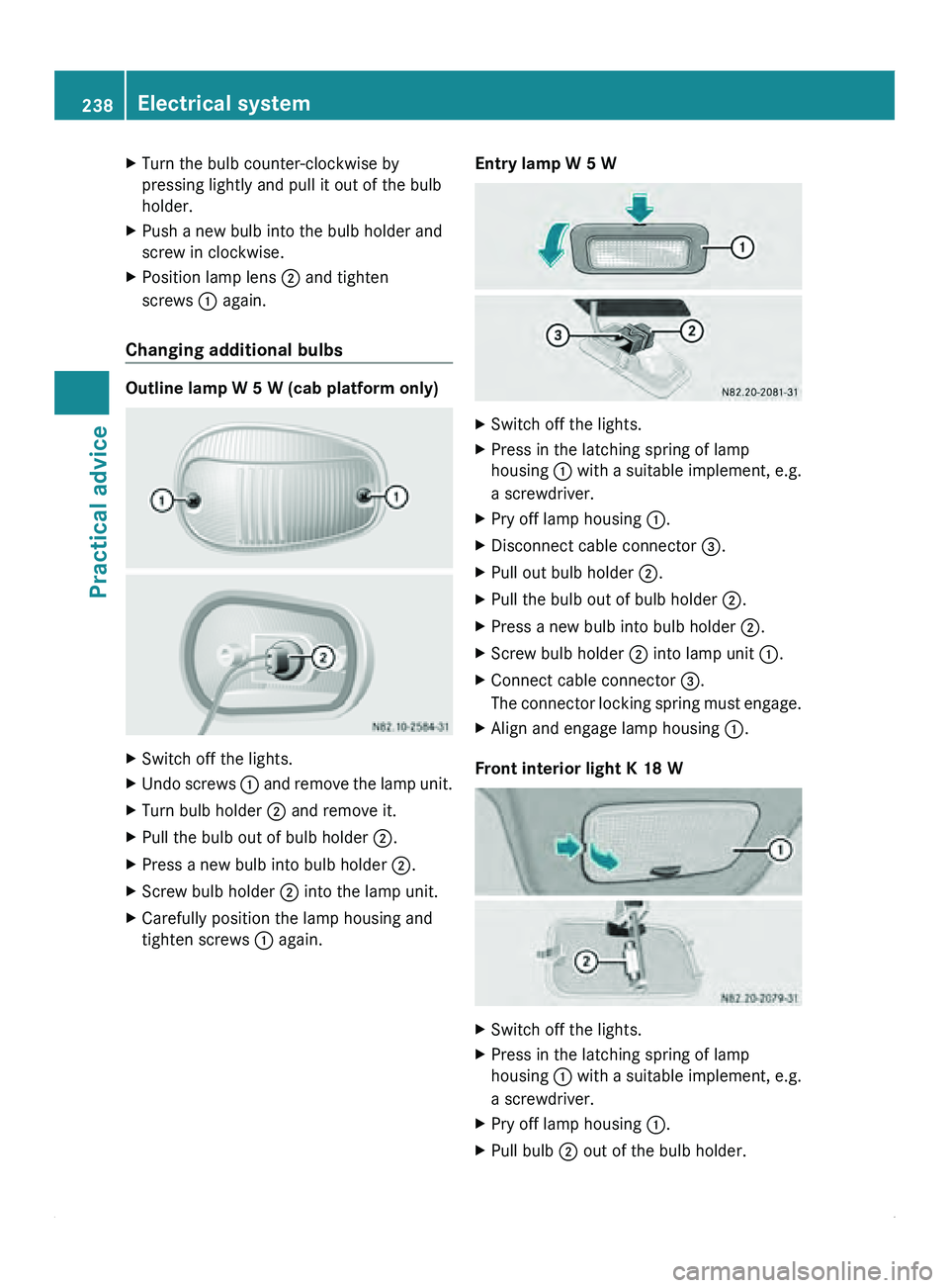
Changing additional bulbs Outline lamp W 5 W (cab platform only)
X
Switch off the lights.
X Undo screws 0046 and remove the lamp unit.
X Turn bulb holder 0047 and remove it.
X Pull the bulb out of bulb holder 0047.
X Press a new bulb into bulb holder 0047.
X Screw bulb holder 0047 into the lamp unit.
X Carefully position the lamp housing and
tighten screws 0046 again. Entry lamp W 5 W X
Switch off the lights.
X Press in the latching spring of lamp
housing 0046 with a
suitable implement, e.g.
a screwdriver.
X Pry off lamp housing 0046.
X Disconnect cable connector 008A.
X Pull out bulb holder 0047.
X Pull the bulb out of bulb holder 0047.
X Press a new bulb into bulb holder 0047.
X Screw bulb holder 0047 into lamp unit 0046.
X Connect cable connector 008A.
The connector
locking
spring must engage.
X Align and engage lamp housing 0046.
Front interior light K 18 W X
Switch off the lights.
X Press in the latching spring of lamp
housing 0046 with a
suitable implement, e.g.
a screwdriver.
X Pry off lamp housing 0046.
X Pull bulb 0047 out of the bulb holder.238
Electrical system
Practical advice
Page 241 of 292
X
Insert new bulb 0047.
X Align and engage lamp housing 0046 on the
right-hand side.
! Have the bulbs for the overhead control
panel interior lights changed at a qualified
specialist workshop which has the
necessary specialist knowledge and tools
to carry out the work required. We
recommend an authorized Sprinter Dealer
for this purpose.
You could
otherwise
damage the overhead
control panel.
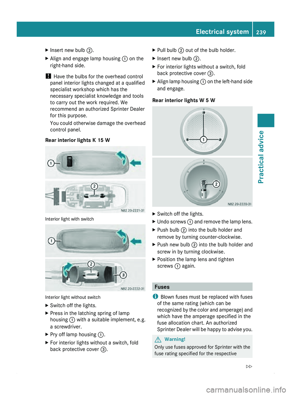
Rear interior lights K 15 W Interior light with switch
Interior light without switch
X
Switch off the lights.
X Press in the latching spring of lamp
housing 0046 with a
suitable implement, e.g.
a screwdriver.
X Pry off lamp housing 0046.
X For interior lights without a switch, fold
back protective cover 008A. X
Pull bulb 0047 out of the bulb holder.
X Insert new bulb 0047.
X For interior lights without a switch, fold
back protective cover 008A.
X Align lamp housing 0046 on the
left-hand side
and engage.
Rear interior lights W 5 W X
Switch off the lights.
X Undo screws 0046
and remove
the lamp lens.
X Push bulb 0047 into the bulb holder and
remove by turning counter-clockwise.
X Push new bulb 0047 into the bulb holder and
screw in by turning clockwise.
X Position the lamp lens and tighten
screws 0046 again. Fuses
i Blown fuses must be replaced with fuses
of the same rating (which can be
recognized by the
color and amperage) and
which have the amperage specified in the
fuse allocation chart. An authorized
Sprinter Dealer will be happy to advise you. G
Warning!
Only use fuses approved for Sprinter with the
fuse rating specified for the respective Electrical system
239
Practical advice
Z
Page 249 of 292
X
Remove implement 0047.
X Refit cover 0046. Jump starting, tow-starting and
towing away
Jump-starting
General notes If the vehicle battery is flat, the engine can be
started from another vehicle using jumper
cables. For this purpose, the vehicle has a
jump-starting connection point in the engine
compartment.
The additional battery in the engine
compartment is
not
suitable for jump-starting
operations. If your vehicle requires jump-
starting, or if you use it to jump-start another
vehicle, use the jump-starting connection
point in the engine compartment. G
Warning
Explosive oxyhydrogen is produced when
batteries are being
charged. When working on
batteries, always make sure that the work
area is well ventilated.
Keep flames and naked lights away from the
battery, and do not smoke.
Prevent the creation of sparks (e.g. when
disconnecting the batteries). Sparks can
ignite the oxyhydrogen gas and cause the
batteries to explode. You and others could be
seriously injured. G
Warning
Due to the gases which escape from batteries,
there is a risk of acid burns when jump-
starting a vehicle.
Do not lean over the battery
while the engine is being jump-started.
! Avoid repeated and lengthy starting
attempts.
Do not use a rapid-charging device to start
the engine. When jump-starting, observe the following
points:
R
jump-starting must only be performed
when the engine and catalytic converter
are cold.
R do not start the engine if the battery is
frozen. Let the battery thaw first.
R when jump-starting, use
only batteries with
the same nominal voltage and a similar
capacity.
R only use jump leads protected against
polarity reversal, with adequate cross-
section and with insulated battery terminal
clamps.
X Make sure that the two vehicles do not
touch.
X Apply the parking brake.
X Move the selector lever of the automatic
transmission to position P.
X Switch off all electrical consumers.
X Switch on the battery isolating switch
(Y page 87).
X Remove the key from the ignition lock.
X Open the hood (Y page 168).
Connecting the jumper cable Connection plan
X
Remove the cover from positive
terminal 0047 of the donor battery.
X First connect one of the positive terminal
clamps of the jumper cable to positive
terminal 0047 of the donor battery. Jump starting, tow-starting and towing away
247
Practical advice Z
Page 250 of 292
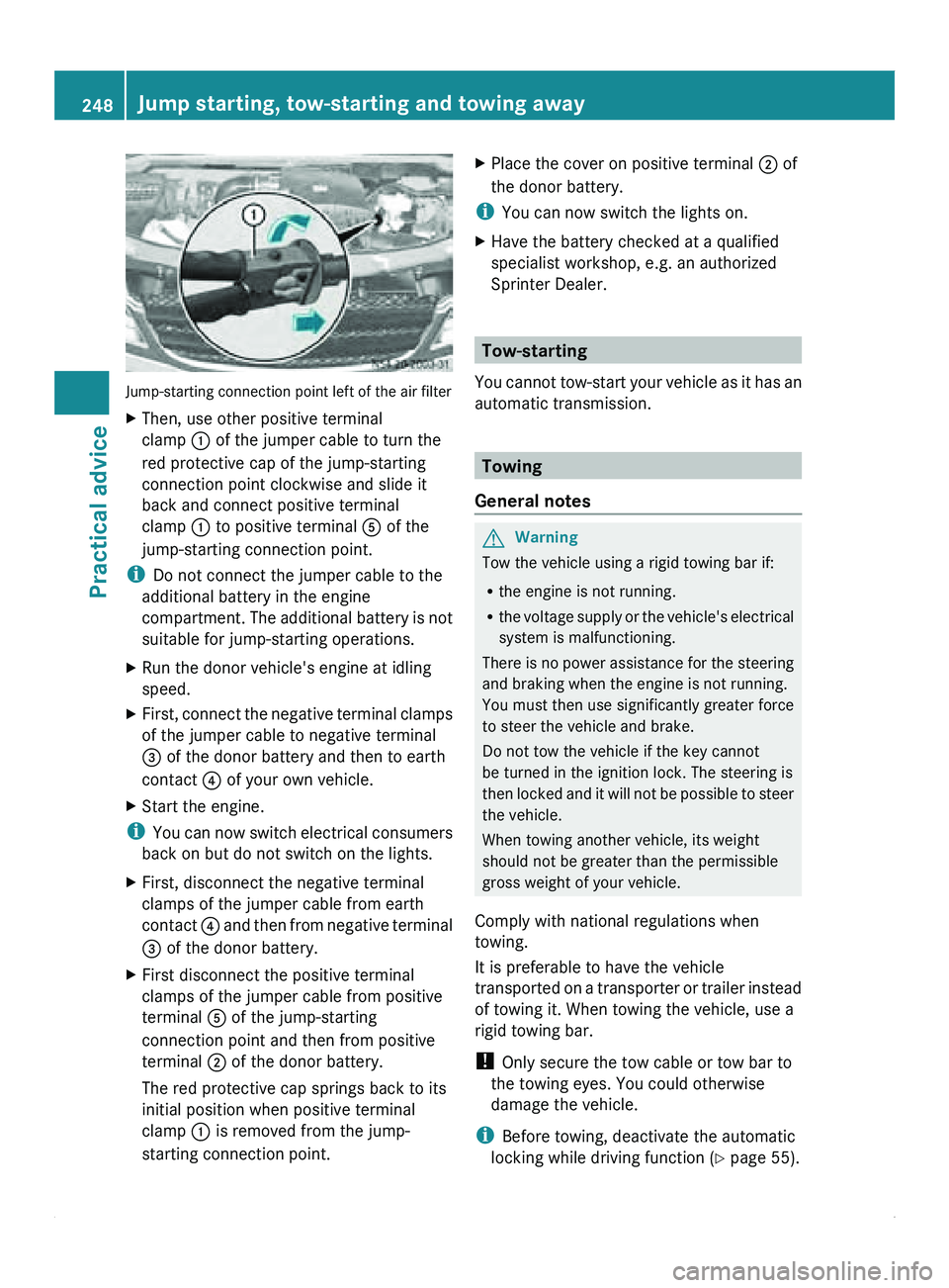
Jump-starting connection point left of the air filter
X
Then, use other positive terminal
clamp 0046 of the jumper cable to turn the
red protective cap of the jump-starting
connection point clockwise and slide it
back and connect positive terminal
clamp 0046 to positive terminal 0086 of the
jump-starting connection point.
i Do not connect the jumper cable to the
additional battery in the engine
compartment. The
additional
battery is not
suitable for jump-starting operations.
X Run the donor vehicle's engine at idling
speed.
X First, connect the negative terminal clamps
of the jumper cable to negative terminal
008A of the donor battery and then to earth
contact 0088 of your own vehicle.
X Start the engine.
i You can
now
switch electrical consumers
back on but do not switch on the lights.
X First, disconnect the negative terminal
clamps of the jumper cable from earth
contact 0088 and then
from negative terminal
008A of the donor battery.
X First disconnect the positive terminal
clamps of the jumper cable from positive
terminal 0086 of the jump-starting
connection point and then from positive
terminal 0047 of the donor battery.
The red protective cap springs back to its
initial position when positive terminal
clamp 0046 is removed from the jump-
starting connection point. X
Place the cover on positive terminal 0047 of
the donor battery.
i You can now switch the lights on.
X Have the battery checked at a qualified
specialist workshop, e.g. an authorized
Sprinter Dealer. Tow-starting
You cannot tow-start
your vehicle as it has an
automatic transmission. Towing
General notes G
Warning
Tow the vehicle using a rigid towing bar if:
R the engine is not running.
R the voltage supply
or the vehicle's electrical
system is malfunctioning.
There is no power assistance for the steering
and braking when the engine is not running.
You must then use significantly greater force
to steer the vehicle and brake.
Do not tow the vehicle if the key cannot
be turned in the ignition lock. The steering is
then locked and it will not be possible to steer
the vehicle.
When towing another vehicle, its weight
should not be greater than the permissible
gross weight of your vehicle.
Comply with national regulations when
towing.
It is preferable to have the vehicle
transported on a transporter or trailer instead
of towing it. When towing the vehicle, use a
rigid towing bar.
! Only secure the tow cable or tow bar to
the towing eyes. You could otherwise
damage the vehicle.
i Before towing, deactivate the automatic
locking while driving function (Y page 55). 248
Jump starting, tow-starting and towing away
Practical advice
Page 260 of 292
Do not overload the tires by exceeding the
specified load limit as indicated on the Tire
and Loading Information placard on the
driver's door B-pillar. Overloading the tires
can overheat them, possibly causing a
blowout. Overloading
the tires can also result
in handling or steering problems, or brake
failure.
Check the tire pressure at least once a month.
Only check and correct tire pressures when
the tires are cold. Checking the tire pressure manually
In order to determine and adjust the tire
pressures, proceed as follows:
X Remove the valve cap of the tire you wish
to check.
X Press the
tire pressure gauge securely onto
the valve.
X Read the tire pressure and compare it with
the recommended value on the Tire and
Loading Information placard12
or on the tire
pressure plate on the B-pillar on the driver's
side of the vehicle.
X If necessary, increase the tire pressure to
the recommended value.
X If the tire pressure is too high, release air
by pressing down
the metal pin in the valve
using the tip of a pen, for example. Then,
check the tire pressure again using the tire
pressure gauge.
X Screw the valve cap onto the valve.
X Repeat the steps for the other tires. Tire pressure monitor
Important safety notes If a tire pressure monitor is installed, the
vehicle's wheels have sensors installed that
monitor the
tire
pressures in all four tires. The
tire pressure monitor warns you when the pressure drops in one or more of the tires. The
tire pressure monitor only functions if the
correct wheel electronics units are installed
in all wheels.
The tire pressure monitor has a yellow
0077
warning lamp in the instrument cluster for
indicating pressure loss/malfunctions (USA)
or pressure loss
(Canada). Depending on how
the warning lamp flashes or lights up, an
underinflated tire or a malfunction in the tire
pressure monitor is displayed:
R if the 0077 warning lamp is lit continuously,
the tire pressure on one or more tires is
significantly too low. The tire pressure
monitor is not malfunctioning.
R USA only: if the 0077 warning lamp flashes
for 60 seconds and then remains lit
constantly, the tire pressure monitor is
malfunctioning. G
Warning
Each tire, including the spare (if provided),
should be checked at least once a month
when cold and inflated to the inflation
pressure recommended by the vehicle
manufacturer on the Tire and Loading
Information placard on the driver’s door B-
pillar or the
tire inflation pressure label on the
inside of the fuel filler flap. If your vehicle has
tires of a different size than the size indicated
on the Tire and Loading Information placard
or the tire inflation pressure label, you should
determine the proper tire inflation pressure
for those tires.
As an added safety feature, your vehicle has
been equipped with a tire pressure monitoring
system (TPMS) that illuminates a low tire
pressure telltale when one or more of your
tires are significantly underinflated.
Accordingly, when the low tire pressure
telltale illuminates, you should stop and check
your tires as soon as possible, and inflate
them to the proper pressure. Driving on a
significantly underinflated tire causes the tire
to overheat and can lead to tire failure.
12 Only for vehicles with a gross vehicle weight rating of less than 10,000 lbs(4536 kg).258
Tire pressure
Wheels and tires