change wheel MERCEDES-BENZ SPRINTER 2015 MY15 Operator’s Manual
[x] Cancel search | Manufacturer: MERCEDES-BENZ, Model Year: 2015, Model line: SPRINTER, Model: MERCEDES-BENZ SPRINTER 2015Pages: 334, PDF Size: 5.94 MB
Page 8 of 334
Warning lamp ................................. 218
Brakes
ABS .................................................. 57
Adaptive Brake Assist .................... 162
Applying the parking brake ............ 150
BAS .................................................. 59
Brake fluid (notes) .........................3 24
Checking brake fluid leve l.............. 254
Display messages .......................... 205
EBD .................................................. 59
Important safety notes .................. 154
Maintenance .................................. 218
Parking brake (notes) ..................... 155
Riding tips ...................................... 154
Breakdown
Fire extinguisher ............................ 276
First-aid kit .................................... 275
Jump-starting ................................. 276
Reflective safety jacket .................. 275
Vehicle tool kit ............................... 274
Warning lamp ................................. 275
Warning triangle ............................ 275
see Flat tire
see Towing away
Bulb
see Changing bulbs
Bulb failure indicator .......................... 92C
Car see Vehicle
Care
Access step in the bumpe r............ 269
Car wash ........................................ 265
Display ........................................... 270
Exterior lights ................................ 268
Interior ........................................... 270
Note s............................................. 265
Paint .............................................. 267
Plastic trim .................................... 270
Power washer ................................ 266
Rear view camera .......................... 269
Roof lining ...................................... 271
Seat belt ........................................ 271
Seat cove r..................................... 271
Selector lever ................................ 270
Sensors ......................................... 268 Sliding door ................................... 269
Steering wheel ............................... 270
Step (electrical) ............................. 269
Trim pieces .................................... 270
Washing by hand ........................... 266
Washing the engine ....................... 266
Wheels ........................................... 267
Windows ........................................ 267
Wiper blades .................................. 268
Cargo compartment
Activating/deactivating ventila-
tion ................................................ 133
Cargo compartment floor ................... 27
Cargo tie-down points and tie
downs
Important safety notes .................. 242
Cargo tie-down rings
Installing ........................................ 244
Permissible tensile load ................. 327
Carrier system
Ladder rack ................................... 245
CD player/CD changer ...................... 188
Cell phone
see Mobile phone
Center console overview .................... 37
Central locking
Automatic locking ............................ 71
Important safety notes .................... 71
Locking/unlocking (buttons) ........... 71
Locking/unlocking (SmartKey )........ 66
Locking/unlocking manually ............ 71
Central locking system
see Central locking
Changing bulbs
Additional indicators (roof) ............ 104
Backup lamp (Chassis Cab) ........... 104
Backup lamps ................................ 103
Bi-Xenon bulbs ................................. 99
Brake lamps ................................... 103
Brake lamps (Chassis Cab) ............ 104
Cornering lamps ............................ 101
Courtesy lights ............................... 105
Daytime running lamps (halogen
headlamps) .................................... 101
Display message ............................ 208
Front interior light .......................... 105
High-beam headlamp s................... 100
Interior light ................................... 105 6
Index
Page 12 of 334
E
EBD (electronic brake force distri-
bution)
Display message ............................ 206
Function/notes ................................ 59
Indicator lamps .............................. 218
Electrical closing assist ...................... 73
Electrical fuses
see Fuses
Electrical step
Cleaning ........................................ .269
Display message ............................ 216
Emergency release .......................... 74
Function .......................................... .74
Important safety notes .................... 73
Indicator lamp ................................ 227
Manual retraction ............................ 74
Obstacle detection ........................... 74
Electrical system
Battery main switch ....................... 137
Electronic brake force distribution
see EBD (electronic brake force
distribution)
Electronic Stability Program
see ESP ®
(Electronic Stability Program)
Emergency exit .................................... 60
Emergency exit window .....................60
Emergency Tensioning Devices
Activation ........................................ .49
Emissions control
Service and warranty information .... 28
Engine
ADR (working speed governor) ...... 172
Changing the power output ............ .25
Check Engine warning lamp .......... .224
Cleaning instructions ..................... 266
Engine number ............................... 317
Engine speed setting (working
mode) ............................................ 173
Irregular running ............................ 141
Jump-starting ................................. 276
Starting .......................................... 139
Starting problems .......................... 141
Switching off .................................. 150
Tow-starting (vehicle) ..................... 280
Engine electronics
Notes ............................................. 316 Problem (malfunction) ................... 141
Engine oil
Adding .......................................... .252
Additives ........................................ 323
Checking the oil level (on-board
computer) ...................................... 250
Checking the oil level using the
dipstick .......................................... 251
Display message ............................ 213
Filling capacity ............................... 323
Information about oil consump-
tion ................................................ 324
Mixing ............................................ 323
Notes about oil grades ................... 322
Oil change ...................................... 323
Oil level (note) ............................... 250
Viscosity ........................................ 322
Warning lamp ................................. 222
Engine speed setting (working
mode) ................................................. 172
Engine, jump-starting ....................... 276
Equipment/conversions ..................... 26
ESP ®
(Electronic Stability Pro-
gram)
Display message ............................ 207
Important safety information ........... 59
Indicator lamp ................................ 221
Warning lamp ................................. 218
Exhaust check ................................... 152
Exhaust gas aftertreatment
DEF level indicator ......................... 182
DEF reducing agent ....................... 320
Diesel Exhaust Fluid (DEF) ............. 320
Display messages (vehicles with
steering wheel buttons) ................. 211
Display messages (vehicles with-
out steering wheel buttons) ........... 200
Indicator lamp ....................... 221, 225
Malfunction ................................... .211
Refilling DEF .................................. 147
Exterior lighting
see Lights
Exterior mirrors
Adjusting ......................................... 89
Important safety notes .................... 89
Eyeglasses compartment ................. 23110
Index
Page 26 of 334
tions when disposing of materials. This helps
to protect the environment. Operating safety and vehicle approval
Important safety notes
G
WARNING
If you do not have the prescribed service/
maintenance work or any required repairs
carried out, this can result in malfunctions or system failures. There is a risk of an accident.
Always have the prescribed service/mainte-
nance work as well as any required repairs
carried out at a qualified specialist workshop.
Air bags and pyrotechnic Emergency Tension-
ing Devices (ETDs) contain perchlorate mate-
rial, which may require special handling and
regard for the environment. The guidelines
must be observed during disposal.
In California, you can find more information
on the Internet at www.dtsc.ca.gov. Notes on operating the vehicle
There is a risk of damage to the vehicle if:
R the vehicle makes contact with the ground,
e.g. on a high curb or a loose road surface
R you drive too quickly over an obstacle, e.g.
a curb or a pothole
R a heavy object hits the underbody or chas-
sis component
In these or similar situations, the vehicle
body/frame, the underbody, chassis compo-
nents, wheels or tires could be damaged even
if this is not visible from the outside. Compo-
nents that have been damaged in this way can
unexpectedly fail or no longer be able to
assimilate the loads occurring in the event of an accident. If the underbody paneling is
damaged, flammable material, such as
leaves, grass or twigs, could collect between the underbody and underbody paneling.
These materials could ignite if they remain in contact with hot components of the exhaust
system for an extended period. G
WARNING
Flammable material such as leaves, grass or
twigs may ignite if they come into contact with hot parts of the exhaust system. There is a risk of fire.
When driving off road or on unpaved roads,
check the vehicle's underside regularly. In
particular, remove parts of plants or other
flammable materials which have become
trapped. In the case of damage, contact a
qualified specialist workshop.
Have the vehicle checked and repaired imme- diately at a qualified specialist workshop. If
you become aware when continuing the jour-
ney that driving safety has been effected,
stop as soon as possible in accordance with
the traffic conditions. In such cases, consult a
qualified specialist workshop. Declaration of conformity
Radio-based vehicle components USA:
"The wireless devices of this vehicle
comply with Part 15 of the FCC Rules. Oper-
ation is subject to the following two condi-
tions: 1) These devices may not cause harm-
ful interference. 2. This device must accept
any interference received, including interfer-
ence that may cause undesired operation.
Changes or modifications not expressly
approved by the party responsible for com-
pliance could void the user’s authority to
operate the equipment."
Canada: "The wireless devices of this vehicle
comply with Industry Canada license-exempt RSS standard(s). Operation is subject to the
following two conditions: 1) These devices
may not cause interference, and 2) these
devices must accept any interference
received, including interference that may
cause undesired operation of the device". 24
Introduction
Page 29 of 334
You alone accept the responsibility if body
manufacturers or dealers make modifications that affect the final certification of the engine,
the vehicle or the equipment. This also
applies to the identification and documenta-
tion of modifications to the affected vehicle
components.
You are responsible for certification and con- firmation that:
R all the applicable standards and regulations
that are affected by the vehicle modifica-
tion are met
R the modified vehicle fulfills the vehicle
safety standards and emissions laws and
regulations
R the modifications or installation of acces-
sories does not affect the safety of the
vehicle
We are not responsible for the final certifica-
tion, product liability or warranty claims
which result from the modifications. This
applies to:
R the modified components, assemblies or
systems
R any resulting noncompliance with any of
the emissions laws and regulations or the
motor vehicle safety standards
R any consequences arising from the
changes that make the vehicle less safe or even render it defective
We do not assume responsibility as the final- stage manufacturer or for the consequential
product liability.
Notes on the radiator Even seemingly small changes to the vehicle,
such as attaching a radiator trim for winter
driving, is not permitted. Do not cover up the radiator. Do not use thermal mats, insect pro-
tection covers or anything similar.
Otherwise, the values of the diagnostic sys-
tem may be affected. Some of these values
are legally prescribed and must always be
correct. Information on the cargo compartment
floor !
The wooden or plastic cargo area floor fit-
ted at the factory is an integral component
of the vehicle structure. The vehicle body
could be damaged if you have the load area floor removed. This then affects the secur-ing of loads and the maximum loading
capacity of the lashing points is no longer
guaranteed.
Therefore, do not have the load area floor
removed. Genuine Mercedes-Benz parts
! Air bags and Emergency Tensioning Devi-
ces, as well as control units and sensors for
these restraint systems, may be installed in the following areas of your vehicle:
R doors
R door pillars
R door sills
R seats
R cockpit
R instrument cluster
R center console
Do not install accessories such as audio
systems in these areas. Do not carry out
repairs or welding. You could impair the
operating efficiency of the restraint sys-
tems.
Have aftermarket accessories installed at a
qualified specialist workshop. H
Environmental note
We supply reconditioned assemblies and
parts which are of the same quality as new
parts. The same New Vehicle Limited War-
ranty applies as for new parts.
The operating safety of the vehicle could be
jeopardized if you use parts, tires and wheels
as well as accessories relevant to safety
which have not been approved by Mercedes-
Benz. This could lead to malfunctions in Introduction
27 Z
Page 30 of 334
safety-relevant systems, e.g. the brake sys-
tem. Only use genuine Mercedes-Benz parts
or parts of equal quality. Only use tires,
wheels and accessories that have been spe-
cifically approved for your vehicle.
We test genuine Sprinter parts, as well as
conversion parts and accessories that have
been specifically approved for the type of
vehicle, for:
R reliability
R safety
R suitability
Despite ongoing market research, Mercedes- Benz is unable to assess other parts. There-
fore, we accept no responsibility for the use of
such parts in Sprinter vehicles, even if they
have been officially approved or independ-
ently approved by a testing center.
In some countries, certain parts are only offi- cially approved for installation or modification
if they comply with legal requirements. All
genuine Sprinter parts satisfy these require-
ments. Make sure that all parts are suitable
for your vehicle.
Always specify the vehicle identification num- ber (VIN) and engine number when ordering
genuine Sprinter parts (Y page 316).Service and vehicle operation
Maintenance and literature
The Service and Warranty Information Book-
let contains detailed information on the types
of warranty that your Sprinter is covered by,
including:
R New Vehicle Limited Warranty
R Diesel Engine Limited Warranty
R Anti-Perforation Warranty
R Limited Warranty for Restraint Systems
(only vehicles that have been sold and reg- istered in the state of Kansas)
R Legally required Emission Performance
Warranty Replacement parts and accessories are sub-
ject to the Replacement Part and Accessory
Warranty of the dealer mentioned on the
inside cover. You can obtain these from any
authorized Sprinter dealer. Maintenance
The Maintenance Booklet and the Service and
Warranty Information Booklet describe all
necessary maintenance work that should be
carried out at regular intervals.
When you take the vehicle to an authorized
Sprinter dealer, always be sure to bring the
Maintenance/Service/Warranty Information
Booklet. Your customer service advisor
enters each maintenance service into the
Maintenance Booklet for you. Registering your vehicle
We may ask our authorized Sprinter Dealers
to carry out technical inspections on certain
vehicles to improve their quality or safety.
We can only inform you about vehicle checks if we have your registration data.
Your registration data is not stored if:
R you did not purchase your vehicle at an
authorized Sprinter Dealer.
R your vehicle has never been inspected at an
authorized Sprinter Dealer.
It is advisable to register your vehicle with an
authorized Sprinter Dealer. Please inform us
as soon as possible about any change of
address or vehicle ownership. Problems with your vehicle
If you should experience a problem with your
vehicle, particularly one that you believe may
affect its safe operation, we urge you to con-
tact an authorized Sprinter Dealer immedi-
ately to have the problem diagnosed and rec-
tified. 28
Introduction
Page 36 of 334
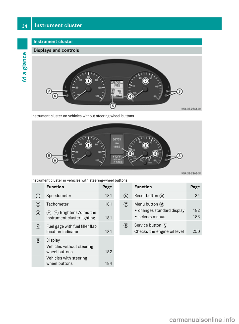
Instrument cluster
Displays and controls
Instrument cluster on vehicles without steering wheel buttons
Instrument cluster in vehicles with steering-wheel buttons
Function Page
0043
Speedometer 181
0044
Tachometer 181
0087
0074,
0075Brightens/dims the
instrument cluster lighting 181
0085
Fuel gage with fuel filler flap
location indicator 181
0083
Display
Vehicles without steering
wheel buttons
182
Vehicles with steering
wheel buttons 184 Function Page
0084
Reset button
0045 34
006B
Menu button
0079 • changes standard display 182
• selects menus 183
006C
Service button
0098 Checks the engine oil level 25034
Instrument clusterAt a glance
Page 88 of 334
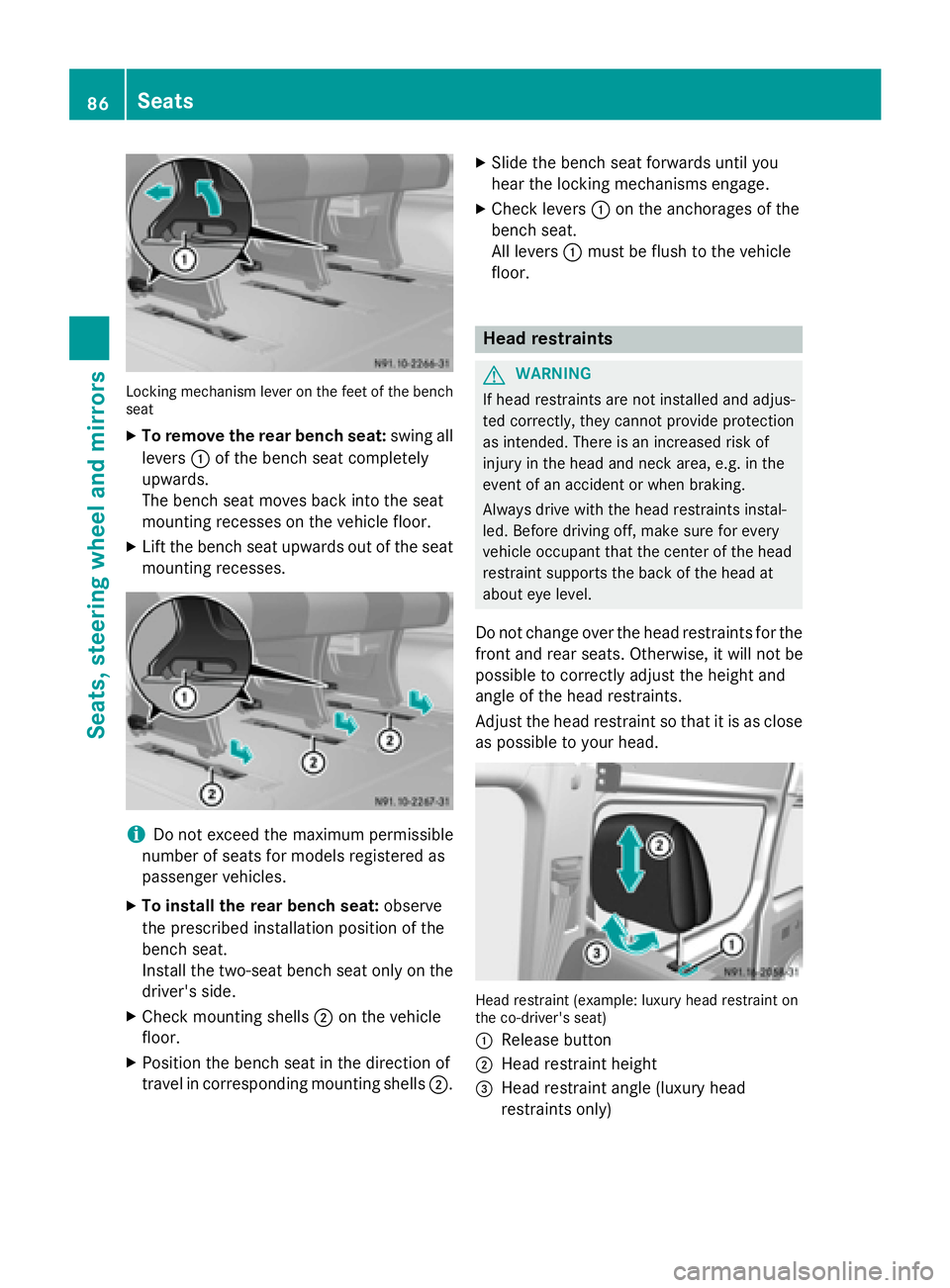
Locking mechanism lever on the feet of the bench
seat
X To remove the rear bench seat: swing all
levers 0043of the bench seat completely
upwards.
The bench seat moves back into the seat
mounting recesses on the vehicle floor.
X Lift the bench seat upwards out of the seat
mounting recesses. i
Do not exceed the maximum permissible
number of seats for models registered as
passenger vehicles.
X To install the rear bench seat: observe
the prescribed installation position of the
bench seat.
Install the two-seat bench seat only on the
driver's side.
X Check mounting shells 0044on the vehicle
floor.
X Position the bench seat in the direction of
travel in corresponding mounting shells 0044.X
Slide the bench seat forwards until you
hear the locking mechanisms engage.
X Check levers 0043on the anchorages of the
bench seat.
All levers 0043must be flush to the vehicle
floor. Head restraints
G
WARNING
If head restraints are not installed and adjus-
ted correctly, they cannot provide protection
as intended. There is an increased risk of
injury in the head and neck area, e.g. in the
event of an accident or when braking.
Always drive with the head restraints instal-
led. Before driving off, make sure for every
vehicle occupant that the center of the head
restraint supports the back of the head at
about eye level.
Do not change over the head restraints for the
front and rear seats. Otherwise, it will not be
possible to correctly adjust the height and
angle of the head restraints.
Adjust the head restraint so that it is as close as possible to your head. Head restraint (example: luxury head restraint on
the co-driver's seat)
0043 Release button
0044 Head restraint height
0087 Head restraint angle (luxury head
restraints only) 86
SeatsSeats, steering wheel and mirrors
Page 90 of 334
X
Make sure that the key is in position 1or 2
in the ignition lock.
X To switch on: press the0072button
repeatedly until the desired heating level
has been set.
X To switch off: press the0072button
repeatedly until all indicator lamps go out.
If the indicator lamps of the current heating
level in the 0072button flash, the seat heat-
ing has switched off automatically. In this
case, too many electrical consumers are
switched on or the battery charge is not suf-
ficient. The seat heating will automatically
switch back to the current heating level when
enough on-board voltage is available again. Steering wheel
G
WARNING
You could lose control of your vehicle if you do the following while driving:
R adjust the driver's seat, head restraint,
steering wheel or mirrors
R fasten the seat belt
There is a risk of an accident.
Adjust the driver's seat, head restraint, steer-
ing wheel and mirror and fasten your seat belt before starting the engine. G
WARNING
If the steering wheel is unlocked while the
vehicle is in motion, it could change position
unexpectedly. This could cause you to lose
control of the vehicle. There is a risk of an
accident.
Before starting off, make sure the steering
wheel is locked. Never unlock the steering
wheel while the vehicle is in motion. G
WARNING
Children could injure themselves if they
adjust the steering wheel. There is a risk of
injury. When leaving the vehicle, always take the
SmartKey with you and lock the vehicle. Never
leave children unsupervised in the vehicle.
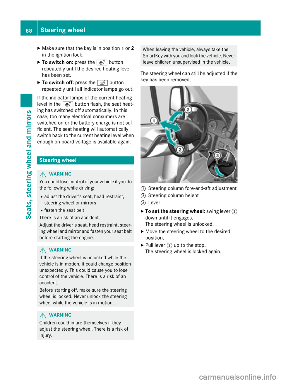
The steering wheel can still be adjusted if the
key has been removed. 0043
Steering column fore-and-aft adjustment
0044 Steering column height
0087 Lever
X To set the steering wheel: swing lever0087
down until it engages.
The steering wheel is unlocked.
X Move the steering wheel to the desired
position.
X Pull lever 0087up to the stop.
The steering wheel is locked again. 88
Steering wheelSeats, steering wheel and mirrors
Page 102 of 334
R
Do not use a bulb that has been dropped or
that has scratches on its glass tube.
The bulb could explode.
R Only use bulbs in closed lamps which have
been designed for this purpose.
R Only use spare bulbs of the same type and
with the prescribed voltage
R Protect the bulbs from moisture when in
use.
If the new bulb still does not light up, consult a qualified specialist workshop.
R Have the LEDs and bulbs of the following
lamps changed at a qualified specialist
workshop:
- the additional turn signals in the exterior
mirrors
- the high-mounted brake lamp
- LED daytime running lamps (Bi-Xenon
headlamps)
- Bi-Xenon lamps (Bi-Xenon headlamps)
- front fog lamps
If you require assistance changing bulbs, con-
sult a qualified specialist workshop. Front bulbs
Overview of bulb replacement – bulb
types The following bulbs can be replaced. Bulb
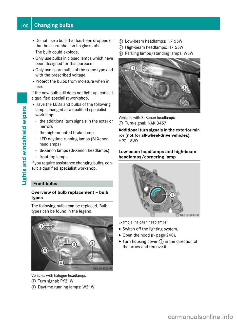
types can be found in the legend. Vehicles with halogen headlamps
0043
Turn signal: PY21W
0044 Daytime running lamps: W21W 0087
Low-beam headlamps: H7 55W
0085 High-beam headlamps: H7 55W
0083 Parking lamps/standing lamps: W5W Vehicles with Bi-Xenon headlamps
0043
Turn-signal: NAK 3457
Additional turn signals in the exterior mir-
ror (not for all-wheel-drive vehicles):
HPC 16WY
Low-beam headlamps and high-beam
headlamps/cornering lamp Example (halogen headlamps)
X Switch off the lighting system.
X Open the hood (Y page 248).
X Turn housing cover 0043in the direction of
the arrow and remove it. 100
Changing bulbsLights and
windshield wipers
Page 145 of 334
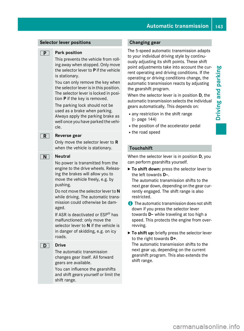
Selector lever positions
0045 Park position
This prevents the vehicle from roll-
ing away when stopped. Only move
the selector lever to Pif the vehicle
is stationary.
You can only remove the key when the selector lever is in this position.
The selector lever is locked in posi- tion Pif the key is removed.
The parking lock should not be
used as a brake when parking.
Always apply the parking brake as
well once you have parked the vehi-
cle. 0046 Reverse gear
Only move the selector lever to
R
when the vehicle is stationary. 0044 Neutral
No power is transmitted from the
engine to the drive wheels. Releas-
ing the brakes will allow you to
move the vehicle freely, e.g. by
pushing.
Do not move the selector lever to N
while driving. The automatic trans-
mission could otherwise be dam-
aged.
If ASR is deactivated or ESP ®
has
malfunctioned: only move the
selector lever to Nif the vehicle is
in danger of skidding, e.g. on icy
roads. 003A Drive
The automatic transmission
changes gear itself. All forward
gears are available.
You can influence the gearshifts
and shift gears yourself or limit the
shift range. Changing gear
The 5-speed automatic transmission adapts
to your individual driving style by continu-
ously adjusting its shift points. These shift
point adjustments take into account the cur-
rent operating and driving conditions. If the
operating or driving conditions change, the
automatic transmission reacts by adjusting
the gearshift program.
When the selector lever is in position D, the
automatic transmission selects the individual gears automatically. This depends on:
R any restriction in the shift range
(Y page 144)
R the position of the accelerator pedal
R the road speed Touchshift
When the selector lever is in position D, you
can perform gearshifts yourself.
X To shift down: press the selector lever to
the left towards D–.
The automatic transmission shifts to the
next gear down, depending on the gear cur-
rently engaged. The shift range is also
restricted.
i The automatic transmission does not shift
down if you press the selector lever
towards D–while traveling at too high a
speed. This protects the engine from over-
revving.
X To shift up: briefly press the selector lever
to the right towards D+.
The automatic transmission shifts to the
next gear up, depending on the current
gearshift program. This also extends the
shift range. Automatic transmission
143Driving and parking Z