jump start MERCEDES-BENZ SPRINTER 2019 MY19 with 7” screen
[x] Cancel search | Manufacturer: MERCEDES-BENZ, Model Year: 2019, Model line: SPRINTER, Model: MERCEDES-BENZ SPRINTER 2019Pages: 354, PDF Size: 6.15 MB
Page 244 of 354

&
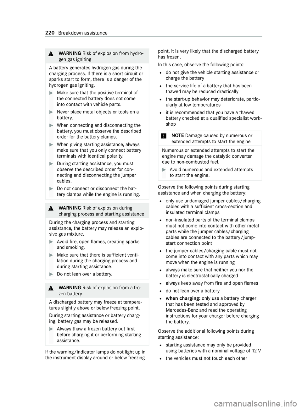
WARNING Risk ofexplosion from hydro‐
ge nga s igniting
A battery generates hydrogen gas during the
ch arging process. If there is a short circuit or
spar ksstart toform ,th ere is a danger of the
hy drogen gas igniting. #
Make sure that the positive term inal of
th e connected battery does not come
into contact with vehicle parts. #
Never place me tal objects or tools on a
batter y. #
When connecting and disconnecting the
batter y,yo u must obse rveth e described
order forth e battery clamps. #
When giving starting assistance, alw ays
make sure that you on lyconnect battery
te rm inals with identical polarity. #
During starting assis tance, you must
obse rveth e described order for con‐
necting and disconnecting the jumper
cables. #
Do not connect or disconnect the bat‐
te ry cla mp s while the engine is running. &
WARNING Risk ofexplosion during
ch arging process and starting assis tance
During thech arging process and starting
assis tance, the battery may release an explo‐
sive gas mixture. #
Avoid fire , open flames, creating spar ks
and smoking. #
Make sure that there is suf ficient venti‐
lation du ring thech arging process and
during starting assis tance. #
Do not lean over a batter y. &
WARNING Risk ofexplosion from a fro‐
zen battery
A dischar ged battery may freeze at temp era‐
tures slightly abo veor below freezing point.
During starting assis tance or battery charg‐
ing, battery gas may be released. #
Alwaysth aw a frozen battery out first
before charging it or per form ing starting
assis tance. If
th ewa rning/indicator lamps do not light up in
th e instrument display around or below freezing point, it is
very likely that the discharged battery
has frozen.
In this case, obser vethefo llowing points:
R do not give theve hicle starting assis tance or
ch arge the battery
R the service life of a battery that has been
th awe d may be reduced drastically
R thest art-up behavior may de teriorate, partic‐
ularly at low temp eratures
R it is recommended that you ha veath awed
battery checked at a qualified specialist work‐
shop
* NO
TEDama gecaused bynume rous or
ex tended attempts tostart the engine Nume
rous or extended attempts tostart the
engine may damage the catalytic con verter
due tonon-combu sted fuel. #
Avoid numerous and extended attem pts
to start the engine. Obser
vethefo llowing points during starting
assis tance and when charging the battery:
R only use undamaged jumper cables/charging
cables with a suf ficient cross-section and
insula tedte rm inal clamps
R non-insulated parts of thete rm inal clamps
must not come into con tact wi thother me tal
parts while the jumper cables/charging
cables are connected tothe battery/jump-
st art connection point
R the jumper cables/charging cable must not
come into contact with any parts which may
mo vewhen the engine is running
R alwa ys make sure that nei ther you nor the
battery is electros tatically charged
R alwayske ep away from fire and open flames
R do not lean over a battery
R when charging: only use a battery charger
th at has been tested and appr ovedby
Mercedes-Benz and read the operating
instructions foryo ur charge r before charging
th e batter y.
Obser vethe additional following points during
st arting assis tance:
R starting assis tance may only be pr ovided
using batteries with a nominal voltage of 12 V
R theve hicles must not touch each other 220
Breakdown assis tance
Page 245 of 354

R
vehicles with a gasoline engine: only per‐
fo rm starting assis tance when the engine and
ex haust sy stem are cold #
Vehicles with a battery main switch: check
whe ther the battery main switch is switched
on (/ page114). #
Secu retheve hicle using the parking brake. #
Vehicles with automatic transmission:
shift the transmission toposition 005D. #
Switch off the ignition and all electrical con‐
sumers. #
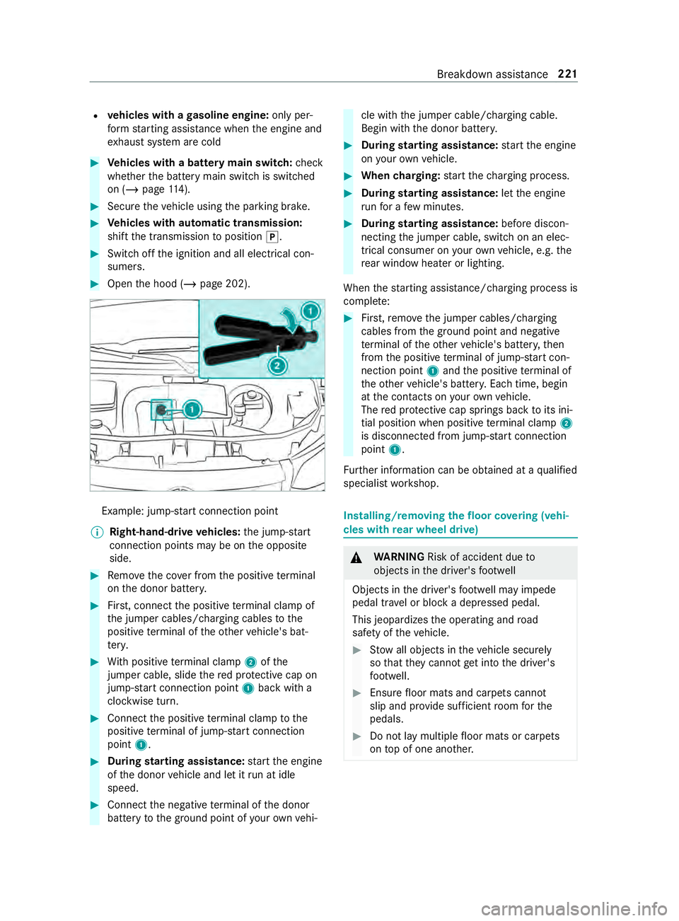
Open the hood (/ page 202). Example: jump-s
tart connection point
% Right-hand-drive
vehicles: the jump-s tart
connection points may be on the opposite
side. #
Remo vethe co ver from the positive term inal
on the donor batter y. #
First, connect the positive term inal clamp of
th e jumper cables/charging cables tothe
positive term inal of theot her vehicle's bat‐
te ry. #
With positive term inal clamp 2ofthe
jumper cable, slide there d pr otective cap on
jump-s tart connection point 1back with a
clockwise turn. #
Connect the positive term inal clamp tothe
positive term inal of jump-s tart connection
point 1. #
During starting assistance: start the engine
of the donor vehicle and let it run at idle
speed. #
Connect the negative term inal of the donor
battery tothe ground point of your ow nve hi‐ cle with
the jumper cable/charging cable.
Begin with the donor batter y. #
During starting assistance: start the engine
on your ow nve hicle. #
When charging: start thech arging process. #
During starting assistance: letthe engine
ru nfo r a few minutes. #
During starting assistance: before discon‐
necting the jumper cable, switch on an elec‐
trical consumer on your ow nve hicle, e.g. the
re ar wind owheater or lighting.
When thest arting assis tance/charging process is
comple te: #
First,re mo vethe jumper cables/charging
cables from the ground point and negative
te rm inal of theot her vehicle's batter y,then
from the positive term inal of jump-s tart con‐
nection point 1and the positive term inal of
th eot her vehicle's batter y.Each time, begin
at the contacts on your ow nve hicle.
The red pr otective cap springs back toits ini‐
tial position when positive term inal clamp 2
is disconnected from jump-s tart connection
point 1.
Fu rther information can be obtained at a qualified
specialist workshop. Installing/removing
thefloor co vering (vehi‐
cles with rear wheel drive) &
WARNING Risk of accident due to
objects in the driver's foot we ll
Objects in the driver's foot we ll may impede
pedal tr avel or block a depressed pedal.
This jeopardizes the operating and road
saf ety of theve hicle. #
Stow all objects in theve hicle securely
so that they cannot getinto the driver's
fo ot we ll. #
Ensure floor mats and carpets cannot
slip and pr ovide suf ficient room forthe
pedals. #
Do not lay multiple floor mats or carpets
on top of one ano ther. Breakdown assis
tance 221
Page 318 of 354

Display messages
Possible causes/consequences and 0050 0050Solutions
To Engage Transmiss.
Position R First Depress
the Brake #
Shift the transmission toposition 005E.
Air Conditioning Malfunc-
tion See Operator's Man-
ual *T
he climate contro l system is functional, subject totemp orary
re strictions. The air quantity and fresh air supply are controlled
automaticall y. #
Have the climate cont rol sy stem checked at a qualified specialist
wo rkshop.
Auxiliary Battery Mal-
function *T
he bac kup battery forth e transmission is not being charge d. #
Visit a qualified specialist workshop. #
Until then, alw ays shift the transmission toposition 005Dmanually
before you swit choff the engine. #
Before leaving theve hicle, apply the parking brake.
Reversing Not Possible
Service Required *T
he transmission is malfunctioning. It is no longer possible toshift
to reve rsege ar. #
Visit a qualified specialist workshop.
Transmission Malfunc-
tion Stop *T
he transmission is malfunctioning. The transmission automatically
shifts toposition 005C. #
Stop in a safe location immediately. #
Shift the transmission toposition 005D. #
Consult a qualified specialist workshop.
0072
Vehicle Operational
Switch the Ignition Off
Before Exiting *Y
ou are about toexitth eve hicle while it is ready tostart. #
When youex itth eve hicle, switch off the ignition and take the
ke y with you. #
Ifyo u do not exitth eve hicle, switch off the electrical consum‐
ers, e.g. the seat heating. Otherwise, the12 ‑Volt‑battery may
discha rge and theve hicle can only be star ted using a boos ter
battery (jump start).
Service Required Do Not
Shift Gears Visit Dealer *T
he transmission is malfunctioning. The transmission position can
no longer be changed. #
Ifth e transmission is in position 005B, visit aqualified specialist
wo rkshop, without changing the transmission position. #
For all other transmission positions, park theve hicle in a safe
location. #
Inform a qualified specialist workshop or the breakdown service.
Only Shift to 'P' when
Vehicle is Stationary *
The transmission can only be brought into position 005Difth eve hicle
is at a standstill.
N Permanently Active
Risk of Rolling Away *W
hile theve hicle is rolling or driving, the transmission was shif ted
to position 005C. #
Tostop, press the brake pedal and, when theve hicle is at a
st andstill, shift the transmission toposition 005D. #
Tocontinue driving, shi ftthe transmission toposition 005Bor005E. 294
Display messages and warning and indicator lamps
Page 338 of 354

Emer
gency
Assis tance overview .......................... .16
Fir st-aid kit (so ftsided) ..................... 216
Saf etyve st ........................................ 216
Wa rning lamp .................................... 216
Emer gency braking
Elect ric pa rking brake ...................... .136
Manual parking brake ....................... 13 4
Emer gency call sy stem
Au tomatic emergency call ............... .217
Information ....................................... 216
Manual emer gency call ..................... 217
Overview ...........................................2 16
Emer gency engine start ..................... .228
Emer gency operation mode
St arting theve hicle .......................... 104
Emer gency Tensioning Devices
Ac tivation ........................................... 29
En gaging drive position (automatic
transmission) ........................................ 11 7
Engaging neut ral (automatic trans‐
mission) ................................................ .116
Engaging reve rsege ar .......................... 11 6
Engaging/disengaging LOW RANGE ...11 9
Engine Engine number ................................ .261
Jump-s tarting .................................... 219
Pa rking (s tart/s top button) .............. 13 2
Problems .......................................... 127
St arting (in emer gency operation
mode) ............................................... 104
St arting (s tart/s top button) .............1 04
Engine data Showing ............................................ 181
Engine electronics (no tes) ...................2 60
Engine number ...................................... 261
Engine oil .............................................. 205
Ad ditive ............................................ 267
Checking the oil le vel (on-board
computer) ........................................ 205
Checking the oil le vel with a dip‐
st ick ................................................ .204
Filling capacity ................................. 268
To pping up .......................................2 05
Engine output Notes on changes .............................. .23
ENR (electronic le vel control) ..............121
Fu nction ............................................ 121
Lo we ring theve hicle .........................1 23
Manually inflating air bello ws............ 124 Problems ..........................................
12 5
Ra ising theve hicle ............................1 23
Entering characters
Fu nction/no tes ................................ 178
Setting theke yboard ........................ 17 9
Using the media display ...................1 79
Environmental pr otection
No tes .................................................. 18
ESC (Electronic Stability Control)
see ESP ®
(Electronic Stability Prog ram)
ESP ®
Crosswind Assist .............................. 13 8
Tr ailer stabilization .......................... .139
ESP ®
(Electronic Stability Prog ram) ...13 8
Ac tivating/deactivating .................... 13 8
Fu nction/no tes ................................ 13 8
Exhaust emission moni toring .............1 07
Exterior lighting Care .................................................. 212
Exterior lighting see Lights F
Fa tigue de tection
see ATTENTION ASSIST
Favo rites
Ad ding .............................................. 17 7
Calling up ........................................ .177
Del eting ............................................ 178
Moving ..............................................1 78
Overview .......................................... 17 7
Re naming ......................................... 178
Firs t-aid kit (soft sided) ........................216
Flat tire .................................................. 218
Changing a wheel ............................ .251
No tes ................................................ 218
Floor co vering
Ins talling/ removing (s tarter bat‐
te ry ) .................................................. 221
Floor mat .................................................78
Fore ign trip
Instructions ...................................... 107
symmetrical low beam ....................... 79
Fr ee software ........................................ .27
Fr equencies
Mobile phone .................................. .260
Tw o-w ayradio .................................. 260
Fr ont airbag (driver, front passenger) .. 32314
Index
Page 340 of 354

Instrument Display
see Warning/indicator lamp
Instrument lighting ..............................16 6
Intelligent light sy stem
Ad aptive Highbeam Assist .................. 81
Corne ring light ................................... 80
In te rior lamps (rear compa rtment)
(replacing the light bulbs) ..................... 88
In te rior lighting
Cargo compartment .......................... .83
Re ar compartment ............................ .83
Setting ................................................ 82
Switch-off del aytime .......................... 83
In te rior motion sensor
Fu nction ............................................. 57
Switching on/off ................................ 57
Interior roof car rier sy stem ................ .199
iPhone ®
see Apple CarPlay™ J
Jack ....................................................... 250
Hydraulic .......................................... 230
Re moving thehy draulic jack from
th estow age compartment .............. .230
St orage location of hydraulic jack .... 230
Jump-start connection .........................219
Jump-starting see Jump-s tart connection K
Ke y........................................................... 41
Battery ............................................... 42
Electrical consu mption ...................... .42
Fu nctions ............................................ 41
Ke yring attachment ........................... 42
Mechanical key .................................. .42
Overview ............................................. 41
Problem ..............................................43
Ra dio connection ................................ 41
Un locking setting .............................. .42L
Labeling (tires) see Tire labeling
Lane de tection (au tomatic)
see Active Lane Keeping Assist
Lane Keeping Assist ............................ .155
Fu nction ........................................... 15 5
Sy stem limitations ............................1 55Tr
ailer operation .............................. .155
Lane Keeping Assist
see Active Lane Keeping Assist
see Lane Keeping Assist
Language ............................................... 181
No tes ................................................ 181
Setting .............................................. 181
LA TC H-type (ISOFIX) child seat
securing sy stem
In stalling ............................................ .36
No tes .................................................36
Le vel control
see ENR (elect ronic le vel control)
License pla telamp (changing bulbs) .... 86
Light switch (o verview) ........................ .79
Lighting see Lights
Lights ...................................................... 79
Ad aptive Highbeam Assist .................. 81
Au tomatic driving lights ...................... 79
Combination switch ............................ 80
Cornering light ................................... 80
Driving abroad (symmetrical low
beam) ................................................. 79
Hazard warning lamps ........................ 80
High beam .......................................... 80
High-beam flasher .............................. 80
Indicator ............................................ .80
Light switch ........................................ 79
Low beam ........................................... 79
Pa rking light ...................................... .79
Re ar fog light ...................................... 79
Re sponsibility with lighting sy stems ... 79
Setting theex terior lighting switch-
off delay time ...................................... 81
Setting the instrument lighting ......... 16 6
Switching the sur round lighting
on/off ................................................ .81
Limiting speed ...................................... 107
Load Determ ining the maximum ................2 41
Sample calculation ........................... 24 2
Load distribution .................................. 19 6
Load index (tire) .................................. .245
Load securing Carg o tie-down point ........................ 197
Ins talling and removing tie-down
ey es .................................................. 19 8
No tes ................................................ 19 6
Load-bea ring capacity (tire) ................245 316
Index