reset MERCEDES-BENZ SPRINTER 2019 MY19 with 7” screen
[x] Cancel search | Manufacturer: MERCEDES-BENZ, Model Year: 2019, Model line: SPRINTER, Model: MERCEDES-BENZ SPRINTER 2019Pages: 354, PDF Size: 6.15 MB
Page 47 of 354
&
WARNING Risk of accident due to
objects in the driver's foot we ll
Objects in the driver's foot we ll may impede
pedal tr avel or block a depressed pedal.
This jeopardizes the operating and road
saf ety of theve hicle. #
Stow all objects in theve hicle securely
so that they cannot getinto the driver's
fo ot we ll. #
Always ins tallth efloor mats securely
and as prescribed in order toensure
th at there is alw ays suf ficient room for
th e pedals. #
Do not use loose floor mats and do not
place floor mats on top of one ano ther. *
NO
TEBattery discharging from using
devices connec tedto the diagnostics
connection Using devices at
the diagnostics connection
drains the batter y. #
Check thech arge leve l of the batter y. #
Ifth ech arge leve l is lo w,charge the bat‐
te ry, e.g. bydriving a considerable dis‐
ta nce. Connecting equipment
tothe diagnostics connec‐
tion can lead toemissions monitoring information
being reset, forex ample. This may lead tothe
ve hicle failing tomeet therequ irements of the
next emissions inspection du ring the main
inspection. Note
s onchanges tothe engine output
Output inc reases can:
R change the emission values.
R lead tomalfunctions.
R result in consequential damage.
The operating saf ety of the engine is not guaran‐
te ed in all situations.
Any tamp ering with the engine management in
order toinc rease the engine output will lead to
th e loss of the New Vehicle Limited Warranty and
ot her warranty entitlements.
If yo u sell theve hicle, inform the buyer of any
alterations totheve hicle's engine output. If you
do not inform the buyer, this may con stitute a
punishable of fense under national legislation. Qualified speciali
stwo rkshop
A qu alified specialist workshop has the necessary
special skills, tools and qualifications tocor rectly
car ryout any necessary workon your vehicle.
This particular lyapplies tosaf ety-re leva nt wo rks.
Alw ays ha vethefo llowing workon theve hicle
car ried out at a qualified specialist workshop:
R safety-re leva nt wo rks
R service and maintenance work
R repair work
R modifications as well as ins tallations and con‐
ve rsions
R workon electronic component parts
Mercedes-Benz recommends that you use an
authorized Mercedes-Benz Center forth is pur‐
pose. Ve
hicle registration
Mercedes-Benz may ask its service cen terto
car ryout tech nical inspections on cer tain vehi‐
cles. The quality or saf ety of theve hicle is
impr oved as a result of the inspection.
Mercedes-Benz can only inform you about vehicle
ch ecks if it Mercedes-Benz has your registration
data.
In thefo llowing cases your vehicle may not be
re gis tere dto yo uye t:
R You did not pur chase your vehicle at an
authorized specialist dealer.
R Your vehicle has not yet been inspected at an
au thorized Mercedes-Benz Center.
It is advisable toregis teryo ur vehicle with an
authorized Mercedes-Benz Center.
Inform Mercedes-Benz as soon as possible about
any change in address or vehicle ownership.
Yo u can do this, forex ample, at an authorized
Mercedes-Benz Center. Cor
rect use of theve hicle
If yo ure mo ve wa rning sticke rs,ot hers may failto
re cognize the dangers. Lea ve warning sticke rs in
position.
Obser vethefo llowing information in particular
when operating theve hicle:
R Safety no tes in these Operating Instructions
R Tech nical da taforth eve hicle General no
tes23
Page 49 of 354
card contains, in compact
form ,th e most impor‐
ta nt information about your vehicle e.g. thero ut‐
ing of electric cables.
Fu rther information can be found at http://
www.mercedes-benz.de/qr-code. Data
storage Electronic control units
Electronic control units are ins
talled in your vehi‐
cle. Some of these are necessary forth e safe
operation of your vehicle, while some assist you
when driving (driver assis tance sy stems). In addi‐
tion, your vehicle pr ovides com fort and enter tain‐
ment functions, which are also made possible by
electronic cont rol units.
The elect ronic control units contain da tamemo‐
ri es which can temp orarily or permanently store
te ch nical information about theve hicle's operat‐
ing state, component loads, main tenance requ ire‐
ments and tech nical events or malfunctions.
In general, this information documents thest ate
of a component part, a module, a sy stem or the
sur roundings such as:
R operating states of sy stem components (e.g.
fl uid le vels, battery status, tire pressure)
R status messages concerning theve hicle and
its individual components (e.g. number of
wheel revo lutions/speed, deceleration, lateral
acceleration, display of thefast ened seat
belts)
R malfunctions or defects in impor tant sy stem
components (e.g. lights, brakes)
R information on events leading tovehicle dam‐
age
R system reactions in special driving situations
(e.g. airbag deployment, inter vention of sta‐
bility control sy stems)
R ambient conditions (e.g. temp erature, rain
sensor)
In addition toprov iding the actual cont rol unit
function, this data assists the manufacturer in
de tecting and rectifying malfunctions and opti‐
mizing vehicle functions. The majority of this data
is temp orary and is only processed in theve hicle
itself. Only a small portion of the data is stored in
th eeve nt or malfunction memo ry.
When your vehicle is serviced, tech nical da ta
from theve hicle can be read out byservice net‐
wo rkemplo yees (e.g. workshops, manufacturers)
or third parties (e.g. breakdown services). Serv‐ ices include
repair services, maintenance pro‐
cesses, warranty claims and quality assurance
measures, forex ample. The read out is per‐
fo rm ed via the legally prescribed port forthe
diagnostics connection in theve hicle. The
re spective service network locations or third par‐
ties collect, process and use this data. They
document tech nical statuses of theve hicle,
assist in finding malfunctions and impr oving qual‐
ity and are transmitted tothe manufacturer, if
necessar y.Fu rthermore, the manufacturer is sub‐
ject toproduct liability. Forth is, the manufacturer
re qu ires tech nical da tafrom vehicles.
Malfunction memories in theve hicle can be reset
by a service outlet as part of repair or mainte‐
nance work.
Depending on the selected equipment, you can
import data into vehicle con venience and info‐
ta inment functions yourself.
This includes, forex ample:
R multimedia data such as music, films or pho‐
to sfo r playback in an integrated multimedia
sy stem
R address book data for use in connection with
an integrated hands-free sy stem or an inte‐
grated navigation sy stem
R entered navigation destinations
R data about the use of Internet services
This data can be sa ved locally in theve hicle or it
is located on a device which you ha veconnected
to theve hicle (e.g. smartphone, USB flash drive
or MP3 pla yer). If this data is stored in theve hi‐
cle, you can dele teit at any time. This data is
sent tothird parties only at your requ est, particu‐
lar lywhen you use online services in accordance
with the settings that you ha veselected.
Yo u can store or change con venience settings/
individualization in theve hicle at any time.
Depending on the equipment, this includes, for
ex ample:
R seat and steering wheel position settings
R suspension and climate cont rol settings
R Individualization such as interior lighting
If yo ur vehicle is accordingly equipped, you can
connect your smartphone or ano ther mobile end
device totheve hicle. You can control this by
means of the cont rol elements integrated in the
ve hicle. Images and audio from the smartphone
can be output via the multimedia sy stem. Cer tain General no
tes25
Page 73 of 354

#
Tounlo ck:pull lo cking pin 2upwards man‐
ually or use the cent ral locking button to
unlo ckthe sliding door (/ page44). #
Press button 1or pull outside handle 3.
The sliding door opens or closes. #
Press button 1again or pull outside handle
3.
The sliding door stops moving. Un
locking the electric sliding door manually If
th ere has been a malfunction or if the battery
has been disconnected, you can use release
cat ch2 todisconnect the sliding door from the
electric mo tor.Then, you can open or close the
door manually. #
Vehicles with comple tesliding door trim:
re mo vethe co ver from release cat ch2.
Service ope ration is accessible. #
Todisconnect the sliding door from the
electric mo tor:turn release cat ch2 180°
clockwise.
The "MAN" position is set. #
Tounlo ck:pull lo cking pin 3upwards man‐
ually or use the cent ral locking button to
unlo ckthe sliding door (/ page44). #
Press button 1. #
Open or close the sliding door with the out‐
side/inside door handle. #
Toconnect the sliding door tothe electric
mo tor:turn release cat ch2 180° counter-
clockwise.
The "AUTO" position is set. #
Adjust the sliding door (/ page 49).
If it is not possible to rectify the malfunction: #
Visit a qualified specialist workshop. Re
setting the electric sliding door Sliding door buttons on
the center console Sliding door button on
the door sill (B-pillar)
Yo u must reset the sliding door if there has been
a malfunction or a voltage supply inter ruption. Opening and closing
49
Page 78 of 354
The windo
wsinthe front doors can also be oper‐
ated automaticall y. #
Toopen comple tely: briefly press button 1
or 2 beyond the point of resis tance.
Au tomatic operation will start. #
Toclose comple tely: briefly pull button 1
or 2 beyond the point of resis tance.
Au tomatic operation will start. #
Tointer rupt automatic operation: briefly
press or pull button 1or2 again.
% If an object bloc
ksa side wind owduring the
automatic closing process, the side window
will open again automaticall y.The automatic
re ve rsing function is only an aid and is not a
substitute foryo ur attentiveness.
% If automatic operation of
the side windo ws
does not work,th ere is no anti-entra pment
function.
Au tomatic reve rsing function of the side win‐
do ws
If an object bloc ksa side wind owduring the clos‐
ing process, the side window will open again
automaticall y.The automatic reve rsing function is
only an aid and is not a substitute foryo ur atten‐
tiveness. #
During the closing process, make sure that no
body parts are in the closing area. &
WARNING Risk of becoming trapped
despite there being reve rse pr otection on
th e side window
The reve rse function does not react:
R Tosoft, light and thin objects, e.g. fingers
R Over the last 00CFin (4 mm) of the closing
path
R During resetting
R When the side window is closed again
manually immediately af ter automatic
re ve rsing
This means that there ve rse function cann ot
pr eve nt someone from becoming trapped in
th ese situations. #
During the closing process, make sure
th at no body parts are in the closing
area. #
If someone becomes trapped, press the
0062 button toopen the side window
again. Ve
ntilating theve hicle before starting a jour‐
ney (co nvenience opening) &
WARNING Risk of entrapment when
opening a side window
When opening a side windo w,parts of the
body could be dr awn in or become trapped
between the side window and window frame. #
When opening, make sure that nobody
is touching the side windo w. #
Release the button immediately if some‐
body becomes trapped. Yo
u can ventilate theve hicle before youstart
driving.
To do this, theke y is used tocar ryout thefo llow‐
ing functions simultaneously:
R unlock theve hicle
R open the side windo ws
The "con venience opening" function can only be
ope rated using thekey. Thekey must be in close
pr ox imity tothe driver's or front-passen ger door. #
Press and hold the0036 button on thekey.
The following functions are per form ed:
R theve hicle is unloc ked
R the side windo wsare opened #
Tointer rupt convenience opening: release
th e0036 button. Closing side windo
wsfrom the outside (con‐
ve nience closing) &
WARNING Risk of entrapment caused by
inadver tent con venience closing
When the con venience closing feature is
operating, parts of the body could become
trapped in the closing area of the side win‐
do ws. #
Obser vethe comple teclosing proce‐
du re when using con venience closing. #
When closing, make su rethat no body
parts are in the closing area. #
Press and hold the0037 button on thekey.
The following functions are per form ed:
R The vehicle is loc ked
R The side windo wsare closed 54
Opening and closing
Page 79 of 354
#
Tointer rupt convenience closing: release
th e0037 button. Re
setting the side windo ws The side windo
wsmust be reset af ter a malfunc‐
tion or a voltage supply inter ruption. #
Swit chon the ignition (/ page103). #
Push bo thwindow lif ter buttons and hold for
appr oximately one second af terth e side win‐
dow has closed. Problems with
the side windo ws Problem
Possible causes/consequences and 0050 0050Solutions
A side window cann otbe
closed and the cause is
not obvious. #
Check tosee if there are any objects in the window guide.
& WARNING Risk of becoming trapped or fata lly injured if reve rs‐
ing pr otection is not activated
If yo u close a side wind owagain immediately af ter it has been
bloc ked, the side window will close with increased or maximum
fo rc e. The reve rsing feature will then not be active.
Pa rts of the body could become trapped in the closing area in the
process. #
Make sure that no parts of the body are in the closing area. #
Tostop the closing process, release the button or press the
button again tore-open the side windo w. If a side window is obstructed during closing, and
reopens again slightl y,
yo u can proceed as follo ws: #
Immedia tely afte rth e window is obstructed, pull the cor responding
button again until the side window has closed, and hold the button
fo r an additional second.
The side window is closed with increased forc e.
If th e side window is obstructed again and reopens slightl y,yo u can pro‐
ceed as follo ws: #
Repeat the pr evious step.
The side window is closed without the automatic reve rsing function.
The side windo wscannot
be opened or closed
using the con venience
opening feature. The SmartK
eybattery is weak or dischar ged. #
Check the battery with the battery check lamp and replace if neces‐
sary (/ page 42). Anti-theft pr
otection Fu
nction of the immobilizer The immobilizer pr
events your vehicle from being
st ar ted without the cor rect key.
The immobilizer is automatically activated when
th e ignition is switched off, and deactivated when
th e ignition is switched on. When leaving
theve hicle, alw aysta ke thekey
with you and lock theve hicle. If theke y is left
inside theve hicle, an yone can start the engine.
% In
theeve ntthe engine does not start despi te
th eve hicle's star ter battery having suf ficient
ch arge ,th e immobilizer is defective. Contact
a qu alified specialist workshop or call
1-800-367-63 72(inthe USA) or
1-800-387-0 100(in Canada). Opening and closing
55
Page 89 of 354
#
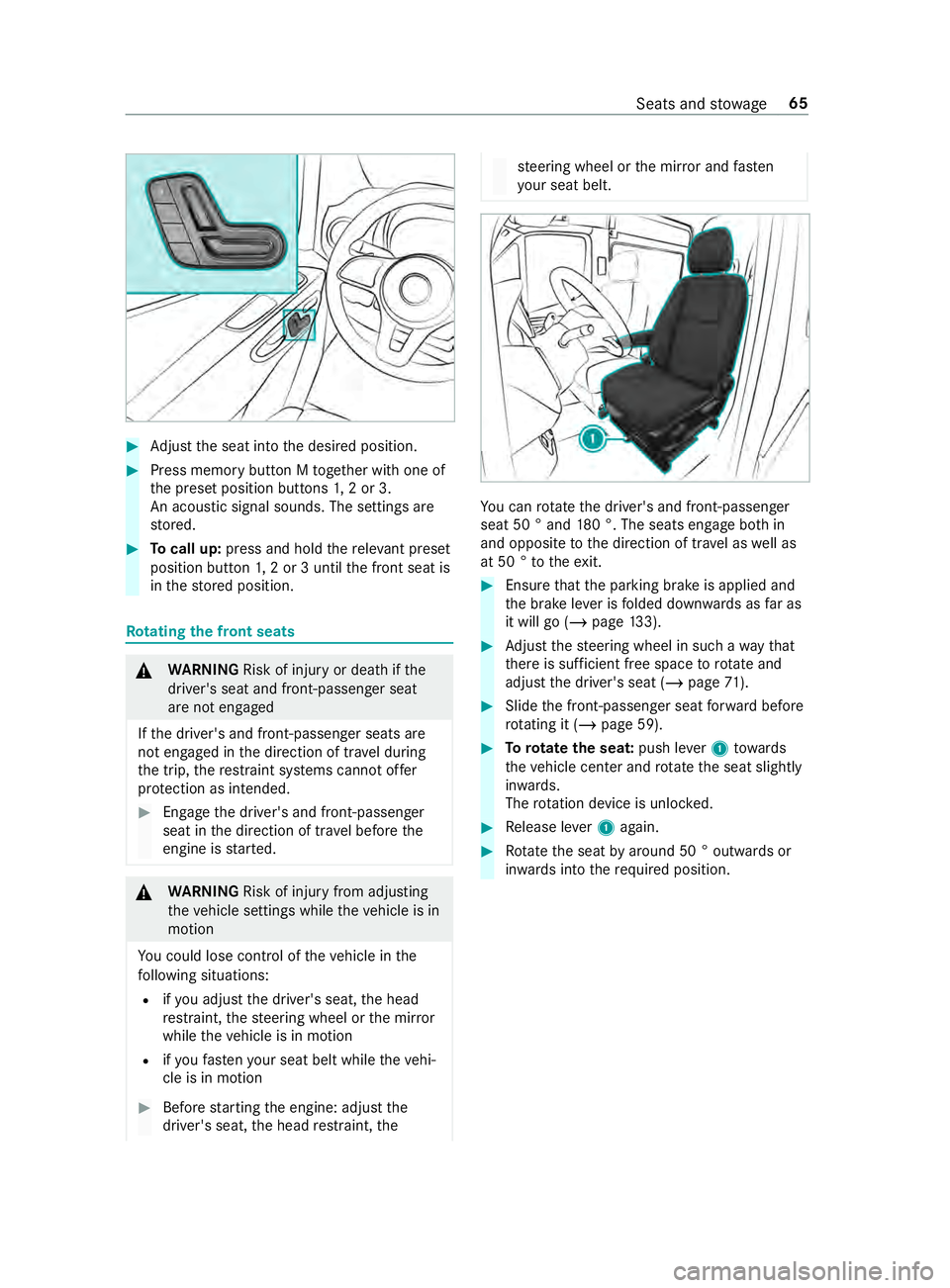
Adjust the seat into the desired position. #
Press memory button M toge ther with one of
th e preset position buttons 1,2 or 3.
An acou stic signal sounds. The settings are
st ored. #
Tocall up: press and hold there leva nt preset
position button 1,2 or 3 until the front seat is
in thestored position. Ro
tating the front seats &
WARNING Risk of inju ryor death if the
driver's seat and front-passen ger seat
are not engaged
If th e driver's and front-passenger seats are
not engaged in the direction of tr avel during
th e trip, there stra int sy stems cann otoffer
pr otection as intended. #
Enga gethe driver's and front-passenger
seat in the direction of tr avel before the
engine is star ted. &
WARNING Risk of inju ryfrom adju sting
th eve hicle settings while theve hicle is in
motion
Yo u could lose control of theve hicle in the
fo llowing situations:
R ifyo u adjust the driver's seat, the head
re stra int, thesteering wheel or the mir ror
while theve hicle is in motion
R ifyo ufast enyour seat belt while theve hi‐
cle is in motion #
Before starting the engine: adjust the
driver's seat, the head restra int, the st
eering wheel or the mir ror and fasten
yo ur seat belt. Yo
u can rotate the driver's and front-passenger
seat 50 ° and 180 °. The seats engage bo thin
and opposite tothe direction of tra vel as well as
at 50 ° totheex it. #
Ensure that the parking brake is applied and
th e brake le ver is folded down wards as far as
it will go (/ page133). #
Adjust thesteering wheel in such a wayth at
th ere is suf ficient free space torotate and
adjust the driver's seat (/ page71). #
Slide the front-passen ger seat forw ard before
ro tating it (/ page 59). #
Torotate the seat: push lever1 towa rds
th eve hicle center and rotat eth e seat slightly
in wa rds.
The rotation device is unloc ked. #
Release le ver1 again. #
Rotate the seat byaround 50 ° out wards or
in wa rds into therequ ired position. Seats and
stowage 65
Page 121 of 354
Switching off automatic climate control
#
Use the0097 rocker switch tochange the air‐
fl ow setting and air distribution
(/ page 97) .
The other setting remains unaf fected bythe
ch ange. Au
tomatically controlling the climate control
in the rear comp artment Re
quirements:
R Rear-compartment climate control has been
swit ched on (/ page 96).
In automatic mode, thete mp erature, air flow and
air distribution are regulated and kept cons tant. #
Press the /00A4
button. #
Press the 0058 button.
% Even if
the front-compartment sy stem is in
automatic mode, there ar-compartment sys‐
te m can exit automatic mode if you adjust
th e blo wer on there ar-compartment menu.
% If
th e air is cooled and the driver, front
passenger or sliding door is opened, there ar
air conditioning sy stem blo wer is turned
down af ter around 15minutes.
When all doors ha vebeen closed again, the
blo wer will be reset tothe pr evious setting
af te r around one minute. Information on
the air distribution settings The symbols on
the display indicate theve nts
th ro ugh which the air is being directed.
TEMPMATIC R 0087 Defros ter and center vents
R 008F Allvents
R 009C Center vents
R 009F Center and foot we llve nts
3-zone au tomatic clima tecontrol
R 0061 Defros terve nts
R 0087 Defros ter and center vents
R 008F Allvents
R 0086 Defros ter and foot we llve nts
R 009C Center vents
R 009F Center and foot we llve nts
R 009B Footwe llve nts Setting the air distribution
Re
quirements:
R The climate control sy stem is switched on. #
Press the 008F button repeatedly until the
desired air distribution appears in the air con‐
ditioning sy stem displa y. Switching
the synchronization function on
and off Re
quirements:
R The climate control sy stem has been
switched on (/ page 95).
The synchronization function cont rols the climate
cont rol function centrally. The settings forthe
te mp erature and air flow inthe front zone are
automatically adop tedfo rth ere ar zone. #
Press the 0015 button.
% If
th ere ar-compartment climate control has
been swit ched off, you can swit chit on auto‐
matically bypressing the0015 button. Re
moving condensation from the windo ws Misting on
the inside of windo ws #
Press the 0064 button.
When the windshield defros ter is switched on,
th ete mp erature and air flow cannot be adjus‐
te d. #
Invehicles with a heating sy stem and a man‐
ual air-conditioning sy stem, also close the
side and center air vent (/ page 98) as well
as the air vents forth ere ar compartment
(/ page 99). #
Vehicles with dual or 3-zone automatic cli‐
mate control: pressthe005A button and, if
necessar y,use the008F button todirect the
air onto the windshield 0061. #
Incre asethe air flow as necessary and close
all air vents (/ page 98). #
Ifth e windo wsremain fogged up: press
th e0064 button.
When the windshield defros ter is switched on,
th ete mp erature and air flow cannot be adjus‐
te d.
0064 or no symbol will appear on the climate
cont rol sy stem displa y. Climate cont
rol97
Page 138 of 354
Diesel pa
rticulate filter Note
s onrege neration &
DANG ER Risk of fata l injuries due to
ex haust gases
Combustion engines emit poisonous exhaust
ga ses such as carbon monoxide. Inhaling
th ese exhaust gases is hazardous tohealth
and can lead topoisoning. #
Never lea vethe engine running in an
enclosed space wi thout suf ficient venti‐
lation. &
WARNING Risk offire caused byhot
ex haust sy stem parts
Flammable material such as lea ves, grass or
twigs may ignite if they come into contact
wi th hot parts of theex haust sy stem or
ex haust gasflow. #
Park theve hicle so that no flammable
material can come into con tact wi thhot
ve hicle components. #
In particular, do not park on dry grass‐
land or har vested grain fields. If
th eve hicle is predominantly used for short dis‐
ta nce driving or extended non-operational times,
th is could lead toa malfunction in the automatic
cleaning function forth e diesel particulate filter.
As a result, permanent blocking of the diesel par‐
ticulate filter may occur and fuel may also accu‐
mulate in the engine oil and cause engine failure.
If yo u main lydrive short dis tances, you should
drive on a free way or go for a country drive for 20
minutes every500 km (300 miles). This facili‐
ta testh e diesel particulate filter's burn-off proc‐
ess.
* NO
TEDama gedue tohot exhaust gases During
rege neration, extremely hot exhaust
ga ses escape from theta ilpipe. #
During rege neration, maintain a mini‐
mum di stance of 7 ft(2 m) from other
objects, e.g. par kedve hicles. Battery main switch
Note
s onthe bat tery main switch *
NO
TEDama getothe electrical sy stem If
yo ure mo veor disconnect the battery main
switch, it could lead tothe electrical sy stem
becoming damaged. #
Make sure that the ignition is switched
off and that at least 15minutes ha ve
passed before removing or reconnecting
th e battery main switch. Otherwise,
electrical sy stem components could be
damaged. Yo
u can use the battery main switch todiscon‐
nect the cur rent toall your vehicle's consumers.
This will pr event uncontrolled battery discha rge
caused byquiescent cur rent consumers.
If yo ur vehicle is equipped with an auxiliary bat‐
te ry inthe engine compartment or in the base of
th e front-passen ger seat, you must disconnect
bo th batteries. Only then is the electrical sy stem
fully disconnected from the po wer supply.
% Only disconnect theve hicle from the po wer
supply using the battery main switch in the
fo llowing situations:
R The vehicle is stationary for a long time
R It is absolutely necessary todisconnect
th eve hicle from the po wer supply
Af ter switching on the po wer supp ly,yo u will
need toreset the side windo ws (/page 53)
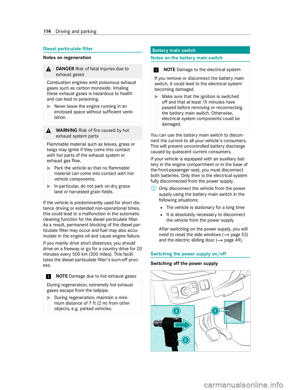
and the electric sliding door (/ page 49). Switching
the po wer supply on/o ff Switching off
the po wer supply 11 4
Driving and pa rking
Page 180 of 354
A
releva nt messa geappears in the instrument
displa y.
The brake application is available in the speed
ra nge between appr oximately 40 mph (60 km/h)
and 100mp h (160 km/h).
Yo u can either deactivate theAc tive Lane Keep‐
ing Assist warning or switch off the sy stem com‐
ple tely.
If yo ufa ilto adapt your driving style, Ac tive Lane
Ke eping Assist can neither reduce therisk of an
accident nor override the la wsof ph ysics. It can‐
not take into account road, weather or traf fic
conditions. The driving sy stem is an aid for when
yo u unin tentionally le aveor cross the lane and
not a sy stem for automatically keeping tothe
lane. You are responsible forth e dis tance tothe
ve hicle in front, forve hicle speed, braking in good
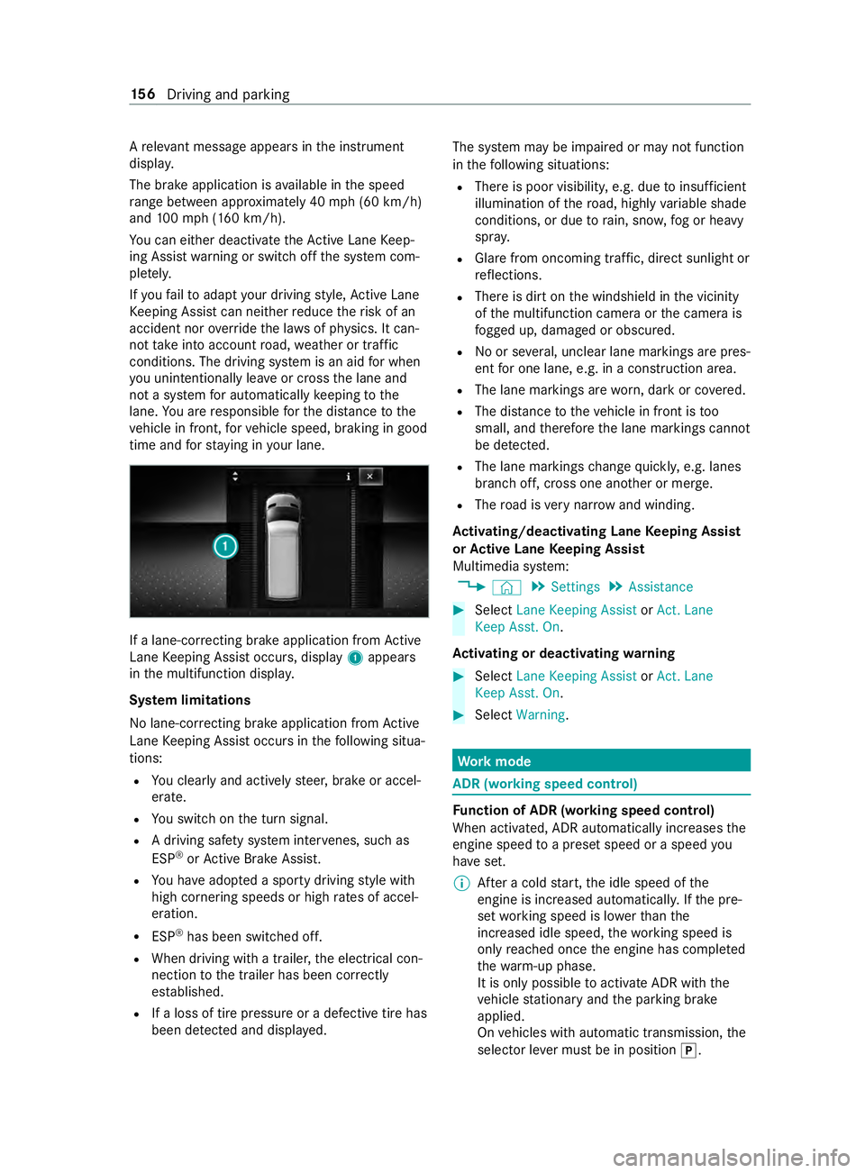
time and forst ay ing in your lane. If a lane-cor
recting brake application from Active
Lane Keeping Assist occurs, display 1appears
in the multifunction displa y.
Sy stem limitations
No lane-cor recting brake application from Active
Lane Keeping Assist occurs in thefo llowing situa‐
tions:
R You clearly and actively steer, brake or accel‐
erate.
R You swit chon the turn signal.
R A driving saf ety sy stem inter venes, su chas
ESP ®
or Active Brake Assi st.
R You ha veadop ted a sporty driving style with
high cornering speeds or high rates of accel‐
eration.
R ESP ®
has been switched off.
R When driving with a trailer, the electrical con‐
nection tothe trailer has been cor rectly
es tab lished.
R If a loss of tire pressure or a defective tire has
been de tected and displa yed. The sy
stem may be impaired or may not function
in thefo llowing situations:
R There is poor visibilit y,e.g. due toinsuf ficient
illumination of thero ad, highly variable shade
conditions, or due torain, sno w,fog or heavy
spr ay.
R Glare from oncoming traf fic, direct sunlight or
re flections.
R There is dirt on the windshield in the vicinity
of the multifunction camera or the camera is
fo gged up, damaged or obscured.
R No or se veral, unclear lane markings are pres‐
ent for one lane, e.g. in a construction area.
R The lane markings are worn, dark or co vered.
R The dis tance totheve hicle in front is too
small, and therefore the lane markings cann ot
be de tected.
R The lane markings change quickl y,e.g. lanes
branch off, cross one ano ther or mer ge.
R The road is very nar row and winding.
Ac tivating/deactivating Lane Keeping Assist
or Active Lane Keeping Assist
Multimedia sy stem:
4 © 5
Settings 5
Assistance #
Select Lane Keeping Assist orAct. Lane
Keep Asst. On.
Ac tivating or deactivating warning #
Select Lane Keeping Assist orAct. Lane
Keep Asst. On. #
Select Warning. Wo
rkmode ADR (working speed control)
Fu
nction of ADR (working speed control)
When activated, ADR automatically increases the
engine speed toa preset speed or a speed you
ha ve set.
% Af
ter a cold start, the idle speed of the
engine is increased automaticall y.Ifth e pre‐
set working speed is lo werth an the
inc reased idle speed, thewo rking speed is
only reached once the engine has comple ted
th ewa rm-up phase.
It is only possible toactivate ADR with the
ve hicle stationary and the parking brake
applied.
On vehicles with automatic transmission, the
selector le ver must be in position 005D. 15 6
Driving and pa rking
Page 191 of 354
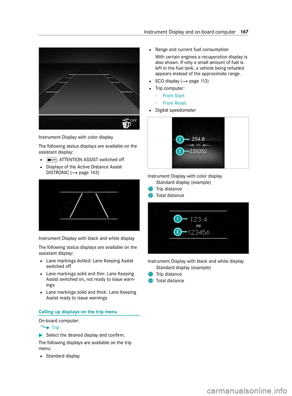
Instrument Display with color display
The
following status displa ysare available on the
assis tant displ ay:
R 00D7 :AT TENTION ASSIST switched off
R Displa ysoftheAc tive Dis tance Assi st
DISTRONIC (/ page 143) In
stru ment Display with black and white display
The following status displa ysare available on the
assis tant displ ay:
R Lane markings dotted: Lane Keeping Assist
switched off
R Lane markings solid and thin: Lane Keeping
Assist switched on, not ready toissue warn‐
ings
R Lane markings solid and thick: Lane Keeping
Assist ready toissue warnings Calling up displa
yson the trip menu On-board computer:
4 Trip #
Select the desired display and confirm.
The following displa ysare available on the trip
menu:
R Standard display R
Range and cur rent fuel consu mption
Wi th cer tain engines a recuperation display is
also shown. If only a small amount of fuel is
left in the fuel tank, a vehicle being refueled
appears ins tead of the appr oximate range.
R ECO displ ay (/page 113)
R Trip computer:
- From Start
- From Reset
R Digital speedom eter Instrument Display with color display
Standard display (e xamp le)
1 Trip dis tance
2 Total dis tance Instrument Display wi
thblack and white display
St andard display (e xamp le)
1 Trip dis tance
2 Total dis tance Instrument Display and on-board compu
ter167