engine MERCEDES-BENZ V-CLASS MPV 2021 Owner's Manual
[x] Cancel search | Manufacturer: MERCEDES-BENZ, Model Year: 2021, Model line: V-CLASS MPV, Model: MERCEDES-BENZ V-CLASS MPV 2021Pages: 337, PDF Size: 9.88 MB
Page 114 of 337
deactivated and
the automatic driving lights acti‐
va ted. Ad
justing the in terior lighting Ad
justing the in terior lighting Fr
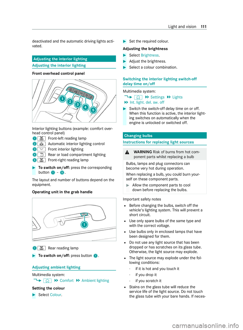
ont overhead control panel In
te rior lighting buttons (e xample: com fort ove r‐
head control panel)
1003D Front-left reading lamp
20033 Automatic interior lighting control
3004A Front interior lighting
40044 Rear or load compartment lighting
5003D Front-ri ghtreading lamp #
Toswitch on/off: pressthe cor responding
button 1–5.
The la yout and number of buttons depend on the
equipment.
Operating unit in thegr ab handle 1003D
Rear reading lamp #
Toswitch on/off: press button1. Ad
justing ambient lighting Multimedia sy
stem:
4 © 5
Comfort 5
Ambient lighting
Setting the colour #
Select Colour. #
Set therequ ired colour.
Ad justing the brightness #
Select Brightness . #
Adjust the brightness. #
Select a colour combination. Switching
the interior lighting switch-off
delay time on/off Multimedia sy
stem:
4 © 5
Settings 5
Lights
5 Int. light. del. sw. off #
Switch the switch-off delay time on or off.
When this function is active, the interior light‐
ing switches on automatically when the
engine is unloc ked or switched off. Changing bulbs
Instructions
forre placing light sou rces &
WARNING Risk of burn s from hot com‐
ponent parts whilst replacing a bulb
Bulbs, lamps and plug connectors can
become very hot during operation.
When replacing a bulb, you could burn your‐
self on these component parts. #
Allow the component parts tocool
down before replacing the bulbs. Impor
tant sa fety no tes
R Before changing the bulbs, switch off the
ve hicle's lighting sy stem. This will pr event a
sho rtcircuit.
R Use only spa rebulbs of the same type and
with the cor rect voltage.
R Use bulbs only in enclosed lamps that ha ve
been designed forth em.
R Do not use any light source that has been
dropped or has scratches on its glass tube.
Otherwise, the light source may explode.
R The light source may explode under thefo l‐
lowing conditions:
- if it is hot and youto uch it
- ifyo u drop it
- ifyo u sc ratch it
R Stains on theglass tube will reduce the
service life of the light source. Do not touch
th eglass tube with your bare hands. If neces‐ Light and vision
111
Page 121 of 337

Re
placing the rear window wiper blade Ta
ilgate #
Fold wiper arm 1away from there ar win‐
dow until it engages in there placement posi‐
tion. #
Hold wiper arm 1firm lyand pull wiper blade
2 offthe wiper arm in the direction of the
ar row. #
Place new wiper blade 2on wiper arm 1. #
Hold wiper arm 1firm lyand push wiper
blade 2inthe opposite direction tothe
ar row until it engages. #
Make sure that wiper blade 2is seated cor‐
re ctly. #
Fold wiper arm 1back onto there ar win‐
do w. Mir
rors Operating
the outside mir rors &
WARNING Risk of injury ifve hicle set‐
tings are adjus ted while theve hicle is in
motion
Yo u could lose control of theve hicle in partic‐
ular in thefo llowing situations:
R Ifyo u adjust the driver's seat, the head
re stra ints, thesteering wheel or the mir‐
ro r while theve hicle is in motion.
R Ifyo ufast enyour seat belt while theve hi‐
cle is in motion. #
Before starting the engine: adjust the
driver's seat, head restra ints, steering
wheel and mir ror in particular and fas‐
te nyo ur seat belt. &
WARNING Risk of accident due tomis‐
judgement of dis tance when using the
outside mir ror
The outside mir rors reflect objects on a
smaller scale. The objects in view are in fact
closer than they appear. #
Therefore, alw ays look overyo ur shoul‐
der in order toensure that you are
aw are of the actual dis tance between
yo u and thero ad users driving behind
yo u. Ad
justing the outside mir rors electrically #
Swit chon the po wer supp lyor the ignition. #
Press button 3or4 toselect the outside
mir rorto be adjus ted. #
Set the position of the mir rorgl ass using but‐
to n2.
Fo lding the electric outside mir rors in/out
* NO
TEDama getothe electric outside
mir rors If
yo ufo ld the electric outside mir rors in or
out manuall y,yo u may damage the outside
mir rors and they will not lock in place prop‐
er ly.
If th e outside mir rors are not folded in when
wa shing theve hicle in a car wash, thewa sher
brushes may fold them in forc ibly and dam‐
age them. #
The outside mir rors must only be folded
in and out elect rical ly. #
Foldthe outside mir rors in before wash‐
ing theve hicle in a car wash. 11 8
Light and vision
Page 122 of 337
#
Switch on the po wer supp lyor the ignition. #
Brief lypress button 1.
Yo u will no lon ger be able tofold in the outside
mir rors once youre ach a speed greaterth an
47 km/h.
En gaging the outside mir rors
If an outside mir ror has been forc ibly disen gaged
fo rw ards or backwards, proceed as follo ws. #
Press and hold button 1until you hear a
click follo we dby the mir ror audibly engaging
in position.
The mir ror housing will now be engaged and
yo u will be able toadjust the outside mir rors
as normal.
Re setting the outside mir rors
% If
th e battery has been disconnected or com‐
ple tely discharged, the outside mir rors must
be reset. Only then will the automatic mir ror
fo lding function workproperly. #
Switch on the po wer supp lyor the ignition. #
Brief lypress button 1.
Heating the outside mir rors
Ve hicles without a rear window heater: at
te mp eratures below 15°C, the mir ror heater will
automatically switch on permanently once the
engine has been star ted.
Ve hicles with a rear window heater: attemp er‐
atures below 15°C, the mir ror heater will auto‐
matically switch on forte n minu tes once the
engine has been star ted. The mir ror heater can
also be switched on toget her with there ar win‐
dow heater. #
Swit chon the ignition. #
Press theto p or bottom section of the006C
rock er switch on the cont rol panel forth e air
conditioning.
The indicator lamp abo vethe006C rock er
switch will light up and the mir ror heater will
be switched on toget her with there ar wind ow
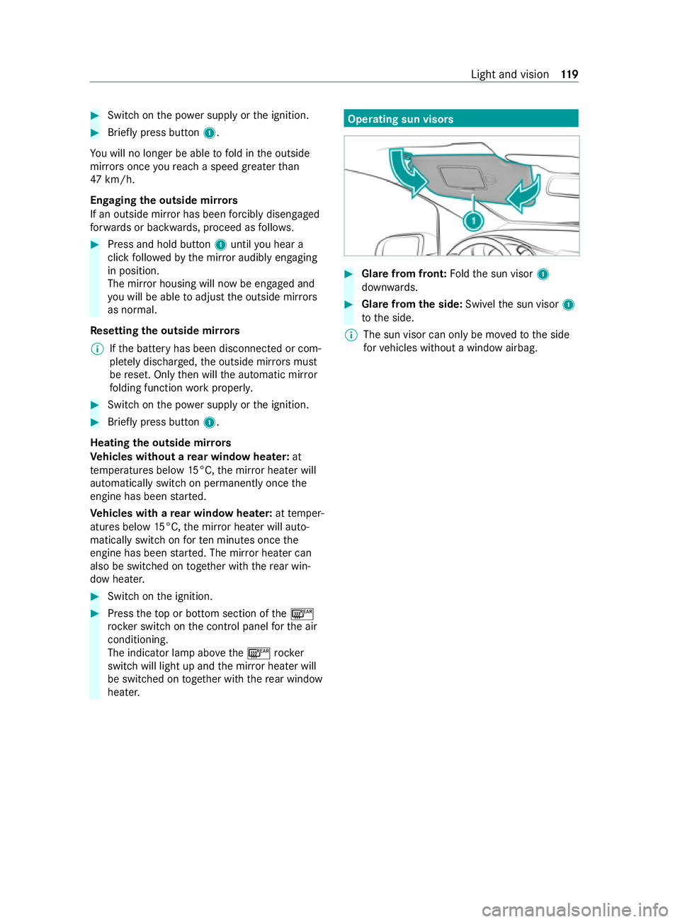
heater. Operating sun visors
#
Glare from front: Foldthe sun visor 1
down wards. #
Glar e from the side: Swivelthe sun visor 1
to the side.
% The sun visor can only be mo
vedto the side
fo rve hicles without a window airbag. Light and vision
11 9
Page 128 of 337

Con
venience opening/closing &
WARNING Risk of entrapment due tonot
paying attention duri ng convenience clos‐
ing
When the con venience closing feature is
operating, parts of the body could become
trapped in the closing area of the side win‐
do ws. #
When the con venience closing feature is
operating, monitor the entire closing
process and make sure that no body
parts are in the closing area. &
WARNING Risk of entrapment from the
con venience opening feature
During con venience opening pa rts of the
body could be dr awn in or become trapped
between the side window and window frame. #
When opening, make sure that nobody
is touching the side windo ws. #
If someone becomes trapped, immedi‐
ately press the0062 button in the door
to open the side windo ws.
The side windo ws stop. #
Tocontinue closing the side windo ws,
pull on the0062 button. #
Con venience closing with the air recircu‐
lation rocker switch: press and hold the
0072 rocker switch up or down until the side
windo wsclose au tomatically.
The indica tor lamp abo vethe0072 rock er
switch lights up. The initial position of the
side windo wsis sa ved. Air-recirculation mode
is activated.
If yo u open the side windo wsmanually af ter
closing them with the con venience closing
fe ature, they will open automatically as far as
th est art position before the con venience
closing. #
Conve nience opening with the air-recircu‐
lation rocker switch: press and hold the
0072 rocker switch up or down until the side
windo wsopen automatically.
The indicator lamp abo vethe0072 rock er
switch goes out. Air-recirculation mode will
be deactivated. #
Pre-entry climate control and con veni‐
ence opening with theke y:press and hold
th e0036 button on thekey.
The side windo wsopen automatically and the
blo wer of the climate cont rol sy stem is activa‐
te d. Switching
there ar window heater on/off The
rear wind owheater consumes a lot of elec‐
tricity. You should therefore switch off there ar
wind owheater as soon as there ar wind owis
clear. #
Swit chon the ignition. #
Press theto p or bottom of the006C rocker
switch.
If th e indicator lamp abo vethe006C rock er
switch lights up, there ar wind owheater is
switched on.
The rear wind owheater will switch off automati‐
cally af ter a few minutes. Switching
there sidual heat utilisation on/off When
the engine is switched off, it is possible to
make use of there sidual heat of the engine to
heat or ventilate theve hicle interior for appro x‐
ima tely 30 minutes. The heating or ventilation
time depends on the set vehicle interior temp era‐
ture. #
Switch off the engine or remo vethekey. #
Toswitch on: presstheto p or bottom sec‐
tion of the! rocker switch.
When residual heat utilisation is switched on,
th e indicator lamp abo vethe! rocker
switch will light up.
The blo wer will run at a low speed rega rdless
of the air flow setting.
If th e "Residual heat" function is switched on
at high outside temp eratures, only thest a‐
tionary ventilation will be switched on. The
bl owe r will then run at medium speed. #
Toswitch off: presstheto p or bottom sec‐
tion of the! rocker switch again.
The indicator lamp abo vethe! rock er
switch goes out. Climate control
12 5
Page 130 of 337

#
Always switch thest ationary heater off
in enclosed spaces without an air
ex traction sy stems, e.g. in garage s. #
Keep theta ilpipe and the area around
th eve hicle free from snow when the
engine or thest ationary heater are run‐
ning. #
Open a window on the windward side of
th eve hicle toensure an adequate sup‐
ply of fresh air. &
WARNING Risk offire due tohot station‐
ary heater components and exhaust
ga ses
Flammable materials such as lea ves, grass or
twigs may ignite. #
When thest ationary heater is swit ched
on, make sure that:
R hot vehicle parts do not come into
contact with flammable materials.
R theex haust gas can flow out of the
st ationary heater exhaust pipe
unhindered.
R theex haust gas does not come into
contact with flammable materials. The heater
forth e auxiliary heating is fitted at the
front of theve hicle underbody. The emissions
outlet is on the left side of theve hicle below the
front door. &
WARNING Risk of poisoning duri ngwork
on the auxiliary warm-air hea ter
If wo rkon the heat exchanger of the auxiliary
wa rm-air hea ter is not per form ed cor rectl y,
ex haust fumes could leak into the passenger
compartment. #
Have all workon the auxiliary warm-air
hea ter car ried out at a qualified special‐
ist workshop. If
yo u are transpo rting hazardous materials, com‐
ply with there leva nt sa fety regulations. Place
objects a suf ficient dis tance from the auxiliary
heating outlet opening.
* NO
TEDama getothe auxiliary heating
due toove rheating If
th eflow of hot air is bloc ked, the auxiliary
heating may overheat and switch off. #
Do not block theflow of hot air. *
NO
TEBattery discharge caused bysta‐
tionary heater or stationary ventilation
ope ration Ope
rating thest ationary heater or stationary
ve ntilation drains the batter y. #
After heating or ventilating theve hicle
twice, drive for a longer period of time. Yo
ur vehicle may be equipped with either a hot-
wate r auxiliary heater or an auxiliary warm-air
hea ter.
The hot-water auxiliary heater is adjusted and
operated using the003B rock er switch on the cli‐
mate cont rol sy stem cont rol panel and via the
multimedia sy stem or byremo tecontrol.
The auxiliary warm-air heater is adjusted and
operated via the switch clock on the lo wer centre
console or byremo tecontrol Hot-water auxiliary heater
Fu
nction of the hot- water auxiliary hea ter
Obser vethe no tes on auxiliary heating
(/ page 126).
The hot-water auxiliary hea ter has a heater boos‐
te r,stationary heater and stationary ventilation
function. In addition, the auxiliary heating sy stem
heats the engine coolant toprotect the engine.
The stationary heater automatically adapts its
operating mode tochanges in outside temp era‐
ture and weather conditions. It is therefore possi‐
ble that thest ationary heater may swit chfrom
ve ntilation toheating mode or from heating to
ve ntilation mode.
The stationary heater will automatically swit ch
itself off af ter a maximum of 50 minutes. The
heater boos ter function helps toheat up theve hi‐
cle while the engine is running and at low outside
te mp eratures.
Yo u can set up tothre e departure times for pre-
entry clima tecontrol byremo tecontrol or via the
multimedia sy stem. The switch-on time is then
calculated based on the outside temp erature and
th e activated departure time. This means that
yo ur vehicle is preheated or precooled bythe set
departure time.
If th e departure time is reached and the engine is
not star ted, the auxiliary heating will continue to Climate cont
rol127
Page 131 of 337
ru
nfo r appro ximately five more minutes. It will
th en switch off automaticall y.
When the auxiliary heating is heating and the
engine is star ted, the heater boos ter function of
th e auxiliary heating will be activated.
When the auxiliary heating is ventilating and the
engine is star ted, the auxiliary heating will be
automatically switched off.
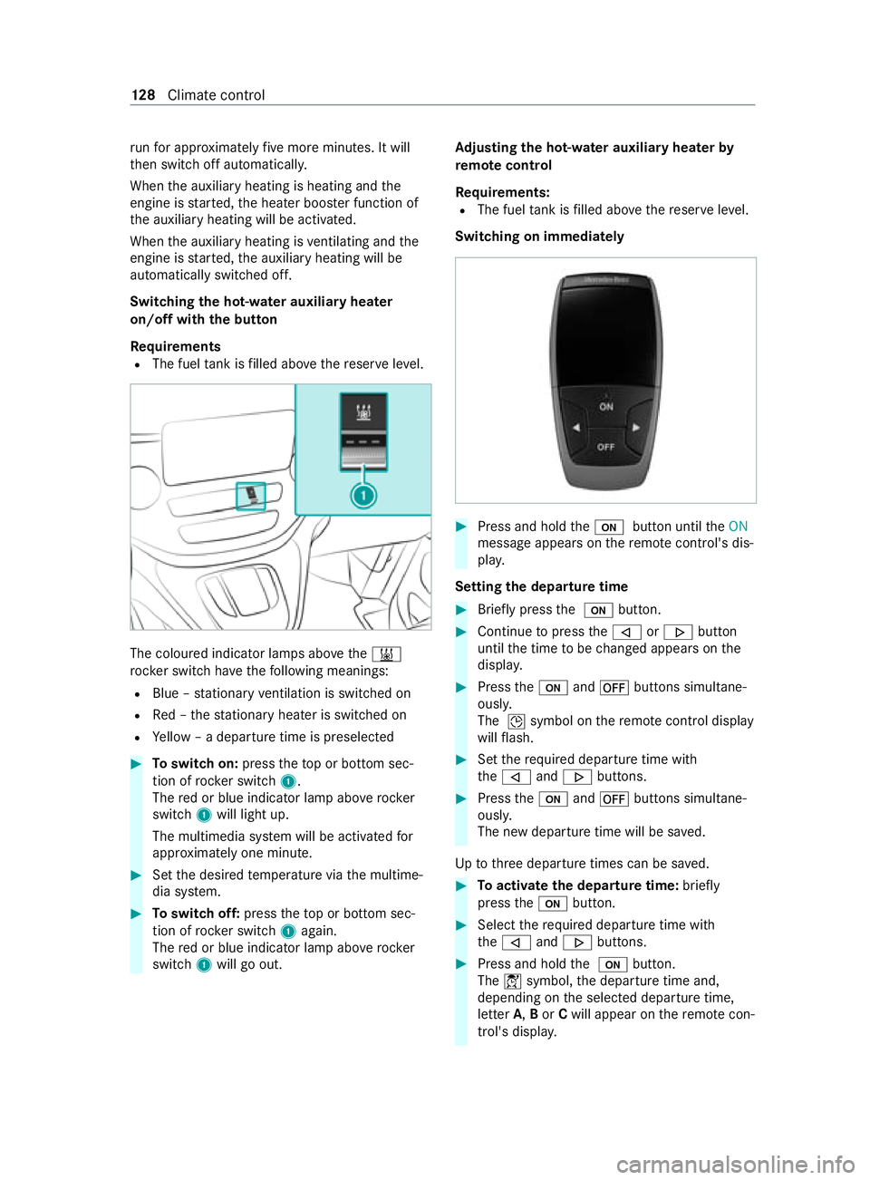
Switching the hot- water auxiliary hea ter
on/off with the but ton
Requ irements
R The fuel tank is filled abo vethere ser veleve l. The coloured indicator lamps abo
vethe003B
rock er switch ha vethefo llowing meanings:
R Blue – stationary ventilation is switched on
R Red – thest ationary heater is swit ched on
R Yellow – a departure time is preselec ted#
Toswitch on: presstheto p or bottom sec‐
tion of rocker switch 1.
The red or blue indicator lamp abo verock er
switch 1will light up.
The multimedia sy stem will be activated for
appr oximately one minute. #
Set the desired temp erature via the multime‐
dia sy stem. #
Toswitch off: presstheto p or bottom sec‐
tion of rocker switch 1again.
The red or blue indicator lamp abo verock er
switch 1will go out. Ad
justing the hot-water auxiliary hea terby
re mo tecontrol
Re quirements:
R The fuel tank is filled abo vethere ser veleve l.
Switching on immediately #
Press and hold the008B button until theON
message appears on there mo tecontrol's dis‐
pla y.
Setting the departu retime #
Brie fly press the 008B button. #
Continue topress the006A or0066 button
until the time tobe changed appears on the
displa y. #
Press the008B and0078 buttons simultane‐
ously.
The 004Dsymbol on there mo tecontrol display
will flash. #
Set therequ ired departure time with
th e006A and0066 buttons. #
Press the008B and0078 buttons simultane‐
ously.
The new departure time will be sa ved.
Up tothre e departure times can be sa ved. #
Toactivate the departu retime: briefly
press the008B button. #
Select there qu ired departure time with
th e006A and0066 buttons. #
Press and hold the 008B button.
The 004Csymbol, the departure time and,
depending on the selected departure time,
letter A,Bor Cwill appear on there mo tecon‐
trol's displa y. 12 8
Climate cont rol
Page 132 of 337
#
Todeactivate the departure time: select
th ere qu ired departure time and press and
hold the0078 button.
OFF will appear on the displa y. #
Tocheck thest atus of the active station‐
ary heater: briefly press the008B button.
Switching off immediately #
Press and hold the 0078 button.
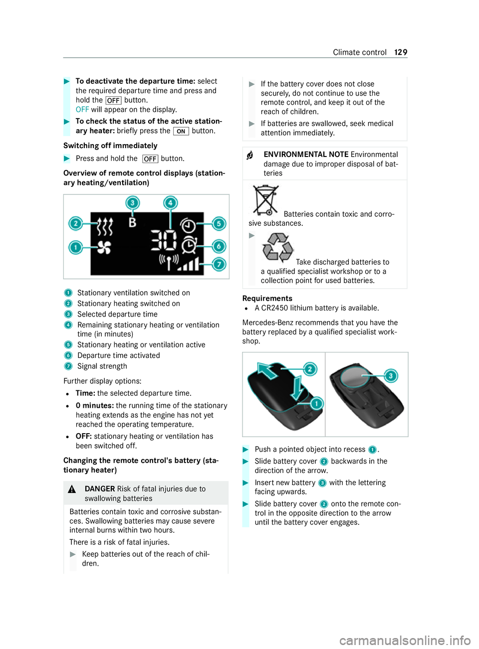
Overview of remo tecontrol displa ys(station‐
ary heating/ventilation) 1
Stationary ventilation switched on
2 Stationary heating swit ched on
3 Selected departure time
4 Remaining stationary heating or ventilation
time (in minu tes)
5 Stationary heating or ventilation acti ve
6 Departure time acti vated
7 Signal stre ngth
Fu rther display options:
R Time: the selected departure time.
R 0 minutes: theru nning time of thest ationary
heating extends as the engine has not yet
re ached the operating temp erature.
R OFF: stationary heating or ventilation has
been switched off.
Changing the remo tecontrol's bat tery (sta‐
tiona ryheater) &
DANG ER Risk of fata l injuries due to
swallowing batteries
Batteries contain toxic and cor rosive subs tan‐
ces. Swallowing batteries may cause se vere
internal burns within two hours.
There is a risk of fata l injuries. #
Keep batteries out of there ach of chil‐
dren. #
Ifth e battery co ver does not close
securely, do not continue touse the
re mo tecontrol, and keep it out of the
re ach of children. #
If batteries are swallo wed, seek medical
attention immediately. +
ENVIRONMEN
TALNO TEEnvironmental
damage due toimproper disposal of bat‐
te ries Batteries contain
toxic and cor ro‐
sive subs tances. #
Ta
ke dischar ged batteries to
a qu alified specialist workshop or to a
collection point for used batteries. Re
quirements
R A CR2450 lithium battery is available.
Mercedes-Benz recommends that you ha vethe
battery replaced byaqu alified specialist work‐
shop. #
Push a pointed object into recess 1. #
Slide battery co ver2 backwards in the
direction of the ar row. #
Insert new battery 3with the lettering
fa cing up wards. #
Slide battery co ver2 onto there mo tecon‐
trol in the opposite direction tothe ar row
until the battery co ver engages. Climate control
12 9
Page 133 of 337

Re
ctifying problems with the hot- water auxili‐
ary hea ter
FA IL00A3 00A3 appea rson there mo tecontrol dis‐
play
Po ssible cause:
R Signal transmission between transmitter and
receiver is malfunctioning. #
Change your position in relation totheve hi‐
cle, moving closer if necessar y.
FA IL appea rson there mo tecontrol display
Po ssible cause:
R The star ter battery is not suf ficiently charge d. #
Charge thest ar ter batter y.
Po ssible cause:
R The fuel tank is not filled up tothere ser ve
le ve l. #
Refuel at the nearest filling station.
FA IL appea rson there mo tecontrol dis‐
play 0099 0099
Po ssible cause:
R The auxiliary heating has malfunctioned. #
Have the auxiliary heating checked at a quali‐
fi ed specialist workshop. Au
xiliary warm-air heater Fu
nction of the auxiliary warm-air heater
Obse rveth e no tes on auxiliary heating
(/ page 126).
The air-intake opening forth e auxiliary warm-air
hea ter is located on the inner side of the left
front seat base. The warm-air outlet is on there ar
side of the left front seat.
The auxiliary warm-air hea ter supplements the
climate control sy stem of your vehicle and has an
auxiliary heating function.
The stationary heater will swit choff automatically
when the engine is switched off or when the set
heating duration has elapsed.
The immediate heating mode of the auxiliary
heating supports the climate cont rol sy stem
when the engine is running and the outside tem‐
perature is lo w. Yo
u ha vethefo llowing options for operating the
auxiliary heating:
R The swit chclock in thestow age compartment
below the cent reconsole
R The switch clock on the lo wer centre console
R Remo tecontrol
Yo u can use the switch clock toset up tothree
departure times for pre-entry clima tecontrol.
Au xiliary warm-air heater switch clo ckove r‐
vi ew
Use the switch clock toconfigu rethefo llowing
settings:
R Swit ching immediate heating mode on/off
R Setting up tothre e preselection times
R Setting the operating duration within a range
of 10 to120 minutes or tocontinuous ope ra‐
tion
R Adjusting the heating le vel (preselec tedte m‐
perature). 1
Program column on the display
0059 Selects preselection memory number
1–3
Mon–Sun, sets da ys
2 Menu bar on the display
0084 Switches immediate heating mode
on/o ff
0045 Setsthe preselection periods
0045 Setsthe da y,time and operating du ra‐
tion
00D1 Setsthe heating le vel
3 Displ aysection for time, heating le vel and
operating duration on the display
00D5 Continuous operation on 13 0
Climate cont rol
Page 139 of 337
Driving
Ke
y positions &
WARNING Risk of accident and inju ry
due toleaving children unat tended in the
ve hicle
If ch ildren are left unat tended in theve hicle,
th ey could, in part icular:
R open doors, thereby endangering other
persons or road users.
R get out and be stru ck byoncoming traf fic.
R operate vehicle equipment and become
trapped, forex ample.
In addition, thech ildren could also set the
ve hicle in motion by,fo rex ample:
R releasing the parking brake.
R changing the transmission position.
R starting theve hicle. #
Never lea vechildren unat tended in the
ve hicle. #
When leaving theve hicle, alw aysta ke
th eke y with you and lock theve hicle. #
Keep theve hicle key out of there ach of
ch ildren. &
DANG ER Risk of death caused by
ex haust gases
Combustion engines emit poisonous exhaust
ga ses such as carbon monoxide. Inhaling
th ese exhaust gases is hazardous tohealth
and leads topoisoning. #
Never lea vethe engine or, if present,
th e auxiliary heating running in an
enclosed space wi thout suf ficient venti‐
lation. &
WARNING Risk offire due toflammable
material in the engine compartment or
th eex haust sy stem
Flammable materials may ignite. #
Therefore, check regularly that there are
no flammable materials in the engine
compartment or on theex haust sy stem. 005A
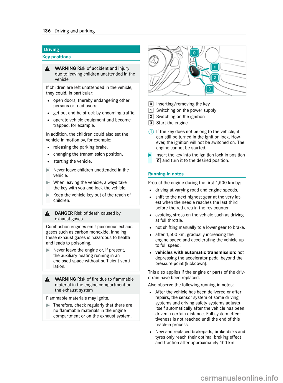
Inserting/ removing thekey
0047 Switching on the po wer supp ly
0048 Switching on the ignition
0049 Start the engine
% If
th eke y does not belong totheve hicle, it
can still be turned in the ignition loc k.How‐
eve r,th e ignition will not be switched on. The
engine cann otbe star ted. #
Insert theke y into the ignition lock in position
005A and turn it tothe desired position. Ru
nning-in no tes Pr
otect the engine during thefirs t1, 500 km by:
R driving at varying road and engine speeds.
R shift tothe next highest gear at theve ry lat‐
est when the needle reaches the last third
before there d area in there v counter.
R avoiding stre ss on theve hicle such as driving
at full thro ttle.
R not shi fting manually toa lo werge ar to brake.
R afte r1, 500 km, gradually increasing the
engine speed and accelerating theve hicle up
to full speed.
R vehicles with automatic transmission: not
depressing the accelerator pedal be yond the
pressure point (kickdown).
This also applies if the engine or parts of the driv‐
et ra in ha vebeen replaced.
Also obser vethefo llowing running-in no tes:
R Afterth eve hicle has been delivered or af ter
re pairs, the sensor sy stem of some driving
sy stems and driving saf ety sy stems adjusts
itself automatically af terth eve hicle has been
driven a cer tain dis tance. Full sy stem ef fec‐
tiveness is not reached until the end of this
te ach-in process.
R New and replaced brakepads, brake disks and
tyres only reach their optimal braking ef fect
and traction af ter appro ximately 10 0 km. 13 6
Driving and pa rking
Page 140 of 337

Un
tilthen, compensate forth ere duced brak‐
ing ef fect by applying greater pressure tothe
brake pedal. Driving tips
Note
s on driving &
WARNING Risk of accident due to
objects in the driver's foot we ll
Objects in the driver's foot we ll may impede
pedal tr avel or block a depressed pedal.
This jeopardises the operating and road
saf ety of theve hicle. #
Stow all objects in theve hicle securely
so that they cannot getinto the driver's
fo ot we ll. #
Ensure floor mats and carpets cannot
slip and pr ovide suf ficient room forthe
pedals. #
Do not lay multiple floor mats or carpets
on top of one ano ther. &
WARNING Risk of accident due toincor‐
re ct foot we ar
Incor rect foot we ar includes, forex ample:
R shoes with plat form soles
R shoes with high heels
R slippers
There is a risk of an accident. #
Alwayswe ar suitable foot we ar so that
yo u can operate the pedals safely. &
WARNING Risk of accident when ignition
switched off due tosteering wheel lock‐
ing
If yo u swit choff the ignition when theve hicle
is stationar y,yo u can no lon gerst eer the
ve hicle. #
Before theve hicle begins toroll, switch
on the ignition todeactivate steering
wheel locking. &
WARNING Risk of accident if the ignition
is switched off while driving
If yo u swit choff the ignition while driving,
saf ety functions are restricted or no longer
av ailable. This may af
fect the po werst eering sy stem
and the brake forc e boosting, forex ample.
Yo u will need touse considerably more force
to steer and brake, forex ample. #
Do not swit choff the ignition while driv‐
ing. &
DANG ER Risk of death caused by
ex haust gases
Combustion engines emit poisonous exhaust
ga ses such as carbon monoxide. Inhaling
th ese exhaust gases is hazardous tohealth
and leads topoisoning. #
Never lea vethe engine or, if present,
th e auxiliary heating running in an
enclosed space wi thout suf ficient venti‐
lation. &
WARNING Risk of skidding and of an
accident due toshifting down on slippery
ro ad sur faces
If yo u shift down on slippery road sur faces to
inc rease the engine braking ef fect, the drive
wheels may lose traction. #
Do not shift down on slippery road sur‐
fa ces toinc rease the engine braking
ef fect. &
DANG ER Risk of fata l injury due topoi‐
sonous exhaust gases
If th eta ilpipe is bloc ked or suf ficient ventila‐
tion is not possible, poisonous exhaust gases
such as carbon monoxide may enter theve hi‐
cle. This is the case when theve hicle
becomes stuck in sn ow,fo rex ample. #
Keep theta ilpipe and the area around
th eve hicle free from snow when the
engine or thest ationary heater are run‐
ning. #
Open a window on the side of theve hi‐
cle facing away from the wind toensure
an adequate supply of fresh air. *
NO
TEDama getothe driv etra in and
engine when pulling away #
Do not warm upthe engine while the
ve hicle is stationar y.Pull away immedi‐
atel y. Driving and pa
rking 137