lock MINI Paceman 2013 Service Manual
[x] Cancel search | Manufacturer: MINI, Model Year: 2013, Model line: Paceman, Model: MINI Paceman 2013Pages: 275, PDF Size: 4.23 MB
Page 228 of 275
Replacing componentsMOBILITY
227
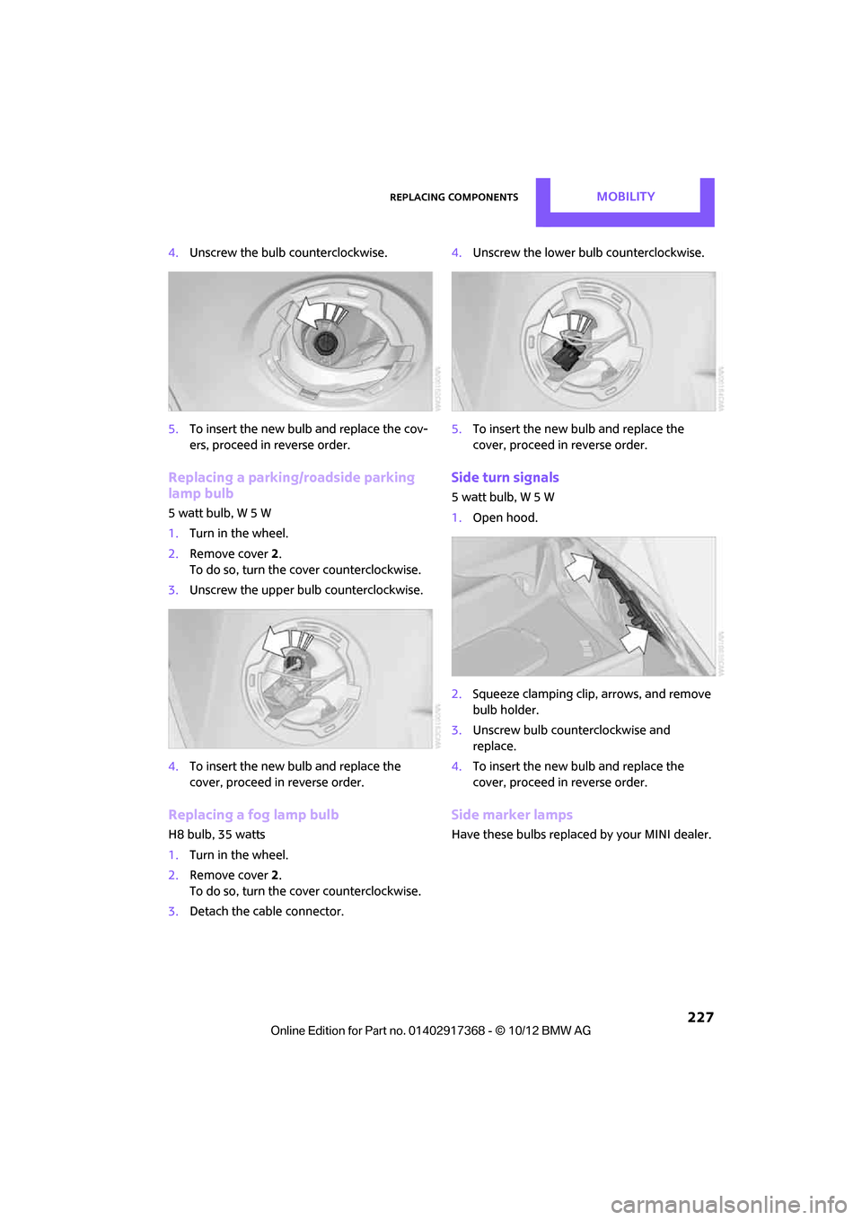
4.Unscrew the bulb counterclockwise.
5. To insert the new bulb and replace the cov-
ers, proceed in reverse order.
Replacing a parking/roadside parking
lamp bulb
5watt bulb, W5W
1.Turn in the wheel.
2. Remove cover 2.
To do so, turn the cover counterclockwise.
3. Unscrew the upper bulb counterclockwise.
4. To insert the new bulb and replace the
cover, proceed in reverse order.
Replacing a fog lamp bulb
H8 bulb, 35 watts
1.Turn in the wheel.
2. Remove cover 2.
To do so, turn the cover counterclockwise.
3. Detach the cable connector. 4.
Unscrew the lower bulb counterclockwise.
5. To insert the new bulb and replace the
cover, proceed in reverse order.
Side turn signals
5watt bulb, W5W
1.Open hood.
2. Squeeze clamping clip, arrows, and remove
bulb holder.
3. Unscrew bulb counterclockwise and
replace.
4. To insert the new bulb and replace the
cover, proceed in reverse order.
Side marker lamps
Have these bulbs replaced by your MINI dealer.
00320051004F004C00510048000300280047004C0057004C005200510003
Page 229 of 275

MOBILITYReplacing components
228
Tail lamps
Bulb P 21 W
MINI Countryman:
1Brake/tail lamp
2 Turn signal
3 Brake/tail lamp
4 Backup lamps
5 Backup lamps
MINI Paceman:
1 Brake light
2 Rear lamp
3 Turn signal
4 Backup lamps
Changing
All bulbs are integrated in a central bulb holder.
MINI Countryman:
1.Switch off the light and remove the infrared
remote control from the ignition lock.
2. Open the tailgate, 3.
Push the cover panel out from the rear of the
cargo area side trim panel and remove it.
4. Open emergency release for the fuel filler
flap, see page 200, and then push to the
side with the foam insert.
Ensure that the emergency release is not
damaged.
5. Disengage the bulb holder by pressing down
on the clamping clip, arrow 1.
6. Take out bulb holder and pull out cable,
arrow 2.
7. Exerting gentle pressure, turn bulb to the left
and remove.
8. To insert the new bulb and install the bulb
holder, proceed in reverse order. Ensure that
the lamp holder engages in all the fasteners.
9. Put foam insert in its original position and
install the emergency fuel flap release.
10. Install cover.
00320051004F004C00510048000300280047004C0057004C005200510003
Page 230 of 275

Replacing componentsMOBILITY
229
MINI Paceman:
1.Switch off the light and remove the infrared
remote control from the ignition lock.
2. Open the tailgate,
3. Remove the cover from the luggage com-
partment side panel.
4. Unlock the retaining element, arrow 1, by
turning it.
5. Remove the screws, arrow 2, using the hex
wrench from the vehicle document case.
6. Remove the tail lamp.
7. Disengage the bulb holder by pressing down
on the clamping clip, arrow 1.
8. Take out bulb holder and pull out cable,
arrow 2. 9.
Exerting gentle pressure, turn bulb to the left
and remove.
10. To insert the new bulb and install the bulb
holder, proceed in reverse order. Ensure that
the lamp holder engages in all the fasteners.
License plate lamps
5watt bulb, C5W
MINI Countryman:
MINI Paceman:
1.Using a screwdriver, push the lamp to the
left in the tab of the lamp housing, arrow 1.
2. Remove the lamp, arrow 2.
3. Replace the bulb.
4. Insert the lamp.
Center brake lamp
This lamp uses LED technology for operation. In
the event of a malfunction, contact your MINI
dealer or a workshop that has specially trained
personnel working in acco rdance with the spec-
ifications of your MINI manufacturer.
00320051004F004C00510048000300280047004C0057004C005200510003
Page 231 of 275
MOBILITYReplacing components
230
Repairing a flat tire
Safety measures in the event of a break-
down:
Park the vehicle as far as possible from moving
traffic and switch on the hazard warning flash-
ers.
Turn the steering wheel until the front wheels
are in the straight-ahead position and engage
the steering wheel lock. Engage the parking
brake and shift into 1st or reverse gear or place
the selector lever in position P.
All passengers should be outside the vehicle and
in a safe place, e.g. behind a guardrail.
Erect a warning triangle or warning flasher at the
appropriate distance if necessary. Comply with
all safety guidelines and regulations. <
In the event of a flat tire, different procedures
should be followed depending on the equip-
ment included in your vehicle:
> MINI Mobility Kit, refer to the following sec-
tion
> Run-flat tires, page 212
MINI Mobility Kit
The Mobility Kit is located under the left front
seat.
Preparations
Use of the MINI Mobility Kit may be ineffective if
the tire puncture measures approx. 1/8 in/4 mm
or more. Contact the nearest MINI dealer if the
tire cannot be made drivable with the Mobility
Kit.
Do not remove foreign bodies which have pen-
etrated the tire if possible.
Follow the instructions on using the Mobil-
ity Kit found on the compressor and the
sealant bottle. <
Remove the adhesive label for the speed limit
from the sealant bottle an d affix it to the steer-
ing wheel.
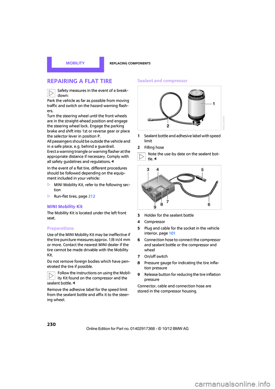
Sealant and compressor
1 Sealant bottle and adhesive label with speed
limit
2 Filling hose
Note the use-by date on the sealant bot-
tle. <
3 Holder for the sealant bottle
4 Compressor
5 Plug and cable for the socket in the vehicle
interior, page 101
6 Connection hose to connect the compressor
and sealant bottle or the compressor and
wheel
7 On/off switch
8 Pressure gauge for indi cating the tire infla-
tion pressure
9 Release button for reduci ng the tire inflation
pressure
Connector, cable and connection hose are
stored in the co mpressor housing.
00320051004F004C00510048000300280047004C0057004C005200510003
Page 233 of 275
MOBILITYReplacing components
232
Correct the tire inflation pressure
1.After driving approx. 3.1 miles/5 km or
ten minutes, stop at a suitable location.
2. Screw the connection hose 6 of the com-
pressor directly onto the tire valve.
3. Insert the plug 5 into the power socket in
the vehicle interior.
4. Adjust tire pressure to 1.8 bar/26 psi. With
the engine running:
> To increase the inflatio n pressure: switch on
the compressor. To ch eck the current infla-
tion pressure, switch off the compressor.
Do not run the comp ressor for longer
than 10 minutes; otherwise, the
device will overheat and possibly be dam-
aged.<
> To decrease the inflation pressure: press the
release button 9.
If the tire cannot m aintain the inflation
pressure, drive the vehicle again, refer to
Distributing the sealan t. Then repeat steps
1to4.
If an inflation pressure of 1.8 bar/26 psi still can-
not be reached, then the tire is too heavily dam-
aged. Contact your ne arest MINI dealer.<
Driving on
Do not exceed the permitted maximum
speed of 50 mph/80 km/h; doing so may
result in an accident. <
Replace the defective tire as soon as possible
and have the new wheel/tire assembly bal-
anced.
Have the Mobility Kit refilled.
Changing wheels
The tire change set is available from as an
optional accessory at your MINI dealer.
Preparing for a wheel change
Observe the safety precautions regarding
flat tires on page 230.<
Additional safety measures when chang-
ing tires:
Only change the tire wh en parked on a surface
that is level, firm and not slippery.
The vehicle or the jack could slip sideways on
soft or slippery support surfaces, such as snow,
ice, flagstones, etc.
Do not use a wooden block or similar object as a
support base for the jack, as this would prevent
it from extending to its full support height and
reduce its load-carrying capacity.
Do not lie under the vehicle or start the engine
when the vehicle is supported by the jack; other-
wise, there is a risk of fatal injury. <
1. Place the foldable chock
behind the front
wheel on the other side of the vehicle or in
front of the wheel if the vehicle is on an
incline. If the wheel is changed on a surface
with a more severe sl ope, take additional
precautions to secure the vehicle from roll-
ing.
2. Uncover the lug bolts if necessary.
3. Loosen the lug bolts by a half turn.
Jacking up the vehicle
The vehicle jack is designed for changing
wheels only. Do not attempt to raise
another vehicle model with it or to raise any load
of any kind. To do so could cause accidents and
personal injury. <
1. Place the jack at the jacking point closest to
the wheel.
The jack base must be perpendicular to the
surface beneath the jacking point.
00320051004F004C00510048000300280047004C0057004C005200510003
Page 240 of 275

Giving and receiving assistanceMOBILITY
239
With towbar
The towing vehicle must not be lighter
than the towed vehicle; otherwise, it may
be impossible to maintain control. <
The tow fittings used should be on the same side
on both vehicles. Should it prove impossible to
avoid mounting the tow bar at an angle, please
observe the following:
> Clearance and maneuv ering capability will
be sharply limited during cornering.
> The tow bar will generate lateral forces if it is
attached offset.
Only attach the tow bar to the tow fittings,
as attachment to other vehicle parts can
lead to damage. <
With tow rope
When starting off in the towing vehicle, make
sure that the tow rope is taut.
To avoid jerking and the associated
stresses on vehicle components when
towing, always use nylon ropes or nylon straps.
Attach the tow rope to the tow fittings only, as
attaching it to other parts of the vehicle could
result in damage. <
With tow truck: vehicles without ALL4
all-wheel drive
MINI Countryman: MINI Paceman:
Have the vehicle transported with a tow truck
with a so-called lift
bar, or on a flatbed.
With tow truck: vehicles with ALL4 all-
wheel drive
Do not have your ve hicle with ALL4 all-
wheel drive towed with the front or rear
axle raised individually; otherwise, the wheels
may lock and the transfer case may be dam-
aged. <
MINI Countryman:
MINI Paceman:
Have the vehicle transp orted on a flatbed sur-
face only.
00320051004F004C00510048000300280047004C0057004C005200510003
Page 260 of 275

Short commands for the voice activation systemREFERENCE
259
Accessing speed limit settings{Speed }
Activating lighting {Lighting }
Selecting the door lock {Door locks }
FunctionCommand
00320051004F004C00510048000300280047004C0057004C005200510003
Page 261 of 275
260
REFERENCEEverything from A to Z
Everything from A to Z
Index
A
ABS Antilock Brake System72
Accepting a call 167,179
Accessories, see Vehicle equipment 4
Acknowledgment signals for locking/unlocking vehicle 28
Activated-charcoa l filter for
automatic climate control 91
Adaptive Light Control 85
Adding engine oil 216
Additives
– coolant 217
– engine oil 216
Address, entering 126
Address for navigation
– entering 120,126
Adjusting temperature inside the car, refer to Air
conditioner 88
Adjusting temperature inside the car, refer to Automatic
climate control 90
Adjusting the tone during audio operation, refer to
Tone control 141
Airbags 81
– sitting safely 38
– warning lamp 83
Air conditioner 88
Air conditioning mode
– air conditioner 88
– automatic cl imate control90
– ventilation 92
Air distribution
– automatic 90
– individual 89
– manual 89 Air flow rate
88,90
– air conditioning system 88
– automatic climate control 90
– heating, ventilation 88
Airing, refer to Ventilation92
Air pressure, checking, refer to
Tire inflation pressure 203
Air recirculation, refer to Recirculated-air
mode 89,90
Air supply
– air conditioner 88
– automatic climate control 90
– ventilation 92
AKI, refer to Fuel grade 201
Alarm system 32
ALL4 all-wheel drive system 74
All-season tires, refer to Winter
tires 213
A ll-wh
ee
l drive, refer to
ALL4 74
AM, waveband 143
Ambient air, refer to
Recirculated-air
mode 89,90
Ambient lighting 87
Antenna, care 220
Antifreeze
– coolant 217
– washer fluid 57
Antilock Brake System ABS 72
Anti-theft alarm system, refer
to Alarm system 32
Approved axle loads, refer to Weights 249
Approved engine oils 216
Approved gross vehicle weight, refer to Weights 249
Armrest, refer to Center armrest 97 Arrival time
– computer
62
– route guidance 129
Ashtray 100
Assistant systems, refer to
– Dynamic Stability Control
DSC 72
Audio 140
– controls 140
– switching on/off 140
– tone control 141
– volume 141
Audio device, external 97
Automatic
– air distribution 90
– air flow rate 90
– cruise control 58
– headlamp control 84
Automatic climate control 88
– automatic air distribution 90
Automatic transmission with Steptronic 52
– Interlock 53
– overriding selector lever lock 54
– Shiftlock 53
– sport program 54
AUTO program for automatic climate control 90
Auxiliary phone 176
AUX-In, refer to External audio device 97
AUX-In connection 153
Average fuel consumption 61
– setting the units 64
Average speed 62
Avoiding highways for navigation 129
Axle loads, refer to
Weights 249
00320051004F004C00510048000300280047004C0057004C005200510003
Page 263 of 275
REFERENCEEverything from A to Z
262
CD, audio playback151
CD player 151
– controls 140
– fast forward/reverse 152
– random order 152
– selecting a track 151
– switching on/off 140
– tone control 141
– volume 141
Center armrest 97
Center brake lamp 229
Center console, refer to Around the center
console 14
Center Rail 99
Center Rail, refer to Storage
compartments 98
Central locking system 27
– Comfort Access 33
– from inside 30
– from outside 27
– setting unlocking
behavior 27
Changing bulbs 224
Changing the language on the
Control Display 69
Changing the measurement units on the Control
Display 64
Changing wheels 232
Charging the battery 234
Chassis number, refer to Engine compartment 214
Check Control 67
Child restraint fixing system LATCH 47
Child restraint systems 46
Child-safety locks 49
Child seats 46
Chrome parts, care 222
Chrome parts, refer to Care 220
Cigarette lighter 100
Cleaning headlamps 57
– washer fluid 57 Clock
– setting time
66
– 12 h/24 h mode 66
Closing
– from inside 30
– from outside 27
Clothes hooks 100
Cockpit 10
Cold start, refer to Starting the engine 51
Comfort Access 33
– replacing the battery 35
– what to observe before
enteri ng a car wash
34
C o
mfort area, refer to Around
the center console 14
Compartment for remote control, refer to Ignition
lock 50
Compass 95
Computer 61
– displays on Control
Display 62
Condensation, refer to When the vehicle is parked 106
Condition Based Service CBS 218
Configuring settings, refer to
Personal Profile 26
Connecting vacuum cleaner,
refer to Connecting electrical
appliances 101
Consumption, refer to Average
fuel consumption 61
Contacts 171,188
– new contact 189
Continuing route guidance 129
Control Display
– adjusting brightness 70
Control Display, refer to iDrive
– switching on/off 16
Control Display, refer to Onboard computer 16
– adjusting brightness 70
Controls and displays 10Control stick, refer to Onboard
computer 16
Control unit, refer to Onboard computer 16
Convenience operation
– windows 28
Convenient access, refer to
Comfort Access 33
Convenient star t, refer to
Starting the engine 51
Coolant 217
– checking level 217
– filling 217
– temperature 217
Cooling, maximum 91
Cooling fluid, refer to
Coolant 217
Copyright 2
Cornering light, refer to
Adaptive Light Control 85
Criteria for route 129
Cruise control
– indicator lamp 13
Cruising range 61
Cupholders 100
Curb weight, refer to Weights 249
Current fuel consumption 62
Curren t playback
– external d
evices156
D
Dashboard, refer to Cockpit 10
Dashboard instruments, refer to Displays 12
Dashboard lighting, refer to Instrument lighting 86
Data 244
– capacities 251
– dimensions 246
– engine 244
– weights 249
Date
– setting 67
– setting format 67
Daytime running lights 85
00320051004F004C00510048000300280047004C0057004C005200510003
Page 264 of 275

Everything from A to ZREFERENCE
263
DBC Dynamic Brake Control, refer to Brake Assist 72
Deactivating front passenger airbags 82
Deadlocking, refer to Locking 28
Defect
– door lock 29
Defective
– fuel filler flap 200
Defining a home address 189
Defogging windows 89,91
Defrosting windows 89,91
Defrosting windows and removing condensation
– air conditioner 89
– automatic climate control 91
Defrosting windshield, refer to Defrosting windows 89,91
Defrost position, refer to Defrosting windows 89,91
Deleting contacts 173,190
Destination address
– entering 120,126
Destination for navigation
– entering 120
– entering via map 125
Differential, breaking in 104
Digital compass 95
Digital radio, refer to HD
Radio 144
Dimensions 246
Dipstick, engine oil 215
Directional indicators, refer to Turn signals 55
Direction announcements,
refer to Voice
instructions 133
Direction instructions, refer to
Voice instructions 133
Directory for navigation, refer to Address book 122
Displacement, refer to Engine data 244
Display, refer to Onboard
computer controls 16Displaying contact
pictures 190
Displaying contacts 172
Displaying special
destinations 125
Display lighting, refer to Instrument lighting 86
Displays 12
– instrument combination 12
– on the Control Display 16
Displays, care 223
Disp lays and controls
10
Disp osal
– of
coolant 217
– remote control battery 35
– vehicle battery 234
Distance, refe r to Computer 62
Distance remaining to service, refer to Service
requirements 64
Distance to dest ination, refer
to Computer 62
Distance warning, refer to Park Distance Control PDC 71
Door key, refer to Integrated
key/remote control 26
Door lock 29
Door lock, confirmation
signals 28
Doors, manual operation 29
DOT Quality Grades 210
Drinks holders, refer to Cupholders 100
Drive-off assistant, refer to Hill
Assist 74
Driving dynamics control, refer
to Sport button 74
Driving lamps, refer to Parking lamps/low beams 84
Driving notes 104
Driving off on inclines, refer to Hill Assist 74
Driving stability control systems 72
Driving through water 105
Driving tips, refer to Driving notes 104 Dry air, refer to Cooling
function 91
DSC Dynamic Stability Control 72
DTC Dynamic Traction Control 73
Dynamic Brake Control DBC,
refer to Brake Assist 72
Dynamic route guidance 136
Dynamic Stability Control
DSC 72
Dynamic Traction Control DTC 73
E
Editing a contact 172
Eject button, refer to Buttons on the CD player 140
Electrical malfunction
– door lock 29
– fuel filler flap 200
Electronic brake-force distribution 72
Electronic Stability Program
ESP, refer to Dynamic
Stability Control DSC 72
E-mail 191
Emergency operation, refer to Manual operation
– door lock 29
– fuel filler flap 200
– transmission lock, automatic
transmission 54
Emergency services, refer to Roadside Assistance 236
Ending a call 168,180
Engine
– breaking in 104
– data 244
– overheated, refer to Coolant temperature 217
– speed 244
– starting, Comfort Access 33
Engine compartment 214
Engine coolant, refer to Coolant 217
00320051004F004C00510048000300280047004C0057004C005200510003