lock MINI Paceman 2013 Owner's Guide
[x] Cancel search | Manufacturer: MINI, Model Year: 2013, Model line: Paceman, Model: MINI Paceman 2013Pages: 275, PDF Size: 4.23 MB
Page 100 of 275
Practical interior accessoriesCONTROLS
99
Center Rail
Various accessory parts can be attached to the
Center Rail and installe d in different positions.
Do not use accessory parts near the hand
brake; otherwise these could be damaged
when the hand brake lever is operated. <
Smartphone holder
The upper part of the smartphone holder can be
rotated by 360°.
When installing in the front of the rail, make sure
that there is sufficient space, e.g., away from the
seat; otherwise, damage may be caused when
rotating.
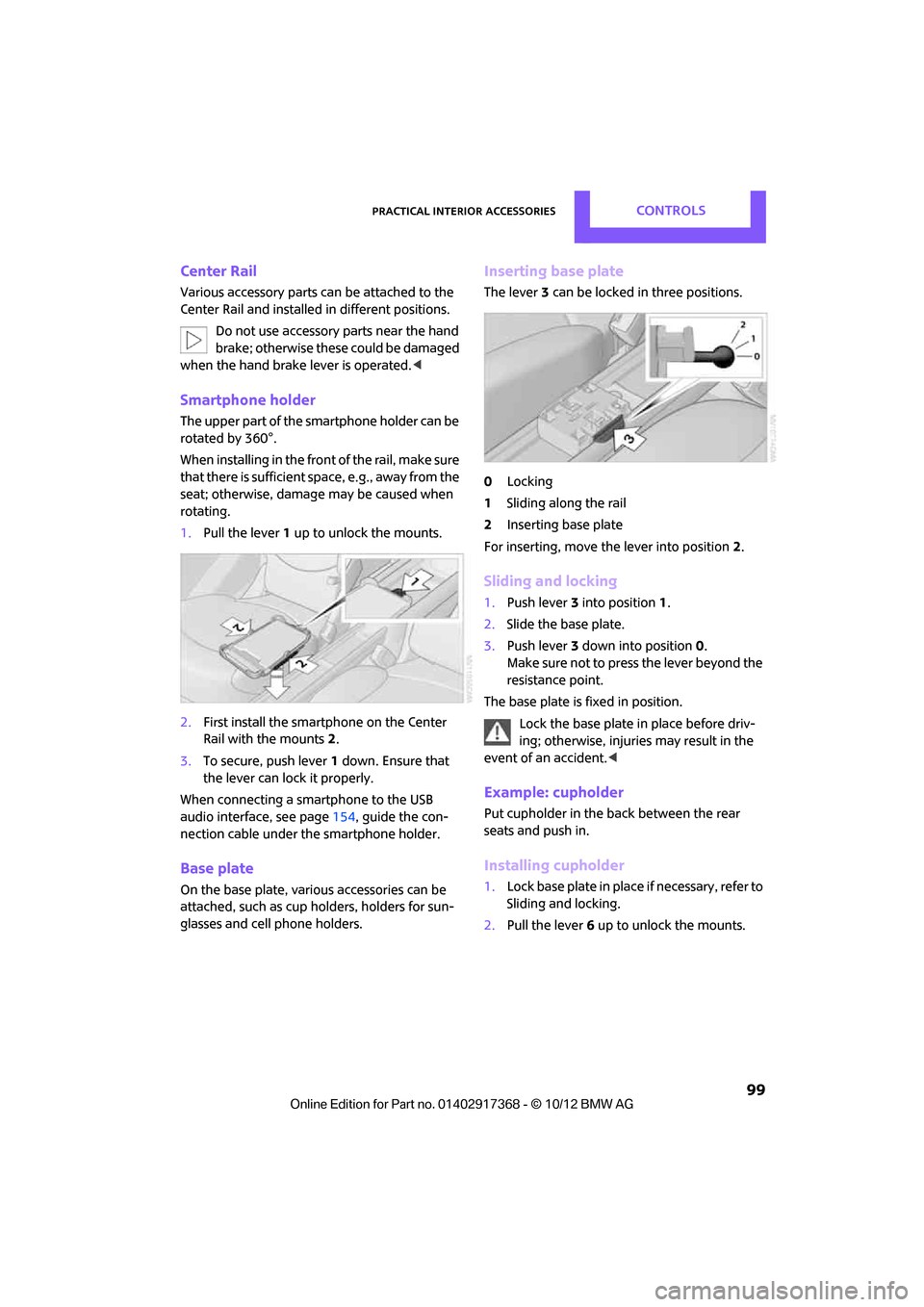
1. Pull the lever 1 up to unlock the mounts.
2. First install the smartp hone on the Center
Rail with the mounts 2.
3. To secure, push lever 1 down. Ensure that
the lever can lock it properly.
When connecting a smartphone to the USB
audio interface, see page 154, guide the con-
nection cable under the smartphone holder.
Base plate
On the base plate, vari ous accessories can be
attached, such as cup holders, holders for sun-
glasses and cell phone holders.
Inserting base plate
The lever 3 can be locked in three positions.
0 Locking
1 Sliding along the rail
2 Inserting base plate
For inserting, move th e lever into position2.
Sliding and locking
1. Push lever 3 into position 1.
2. Slide the base plate.
3. Push lever 3 down into position 0.
Make sure not to press the lever beyond the
resistance point.
The base plate is fixed in position.
Lock the base plate in place before driv-
ing; otherwise, injuries may result in the
event of an accident. <
Example: cupholder
Put cupholder in the back between the rear
seats and push in.
Installing cupholder
1.Lock base plate in plac e if necessary, refer to
Sliding and locking.
2. Pull the lever 6 up to unlock the mounts.
00320051004F004C00510048000300280047004C0057004C005200510003
Page 108 of 275

Things to remember when drivingDRIVING TIPS
107
MINI Paceman:
MINI Countryman: rear seat backrest
Before folding down the rear seat back-
rests, make sure that the range of motion
for the backrests is unobstructed. Particularly
with a folded down midd le section, make sure
that there is no one within the range of motion
of the backrest and that no one reaches into that
region. Otherwise, injury or damage can
result. <
To ensure that the safety systems con-
tinue to provide optimized protection,
observe the safety belt information on
page 42.<
5-seater: the rear seat ba ck is divided in the fol-
lowing proportions: 40-20-40.
When the outer rear seat backs are folded
down, no one may sit in the middle posi-
tion. <
If necessary, remove the third head restraint,
refer to Removing head restraints, page 41.
Open the center belt and insert in the take-up
on the headliner, see page 43.
Expand the cargo area by raising the rear seat
backrests to a steeper angle.
The backrests can be adjusted as needed in
10 stages between a comfort position and a
transport position or can be folded down.
In the comfort position, the backrests are as far
back as possible; in the transport position, they
are in an approximatel y vertical position.
Before installing a ch ild restraint system,
observe the instructio ns starting on page46. 1.
Hold on to the backrest near the top, for
example on the headrest, and pull on the
loop, arrow.
2. Lock backrest in the de sired position or fold
down.
Folding the backrests back into position
When folding the backre st, make sure that
the lock properly engages. Otherwise, for
example during braking and avoidance maneu-
vers, cargo can be thrown into the interior and
endanger the occupants. <
If the rear seat backrests are positioned at
a steeper angle, do not install child
restraint systems in the rear of the vehicle as
their protective featur es may be ineffective.<
When backrests are folded back from the
folded-down position, they lock in the transport
position.
To set the desired backrest angle or a comfort-
able position, pull the lo op forward and adjust
the backrest.
MINI Paceman: rear seat backrest
Before folding down the rear seat back-
rests, make sure that the range of motion
for the backrests is unobstructed; otherwise,
injury or dama ge can result.<
00320051004F004C00510048000300280047004C0057004C005200510003
Page 109 of 275

DRIVING TIPSThings to remember when driving
108
1.Pull on the loop, refer to arrow.
The backrest is unlocked.
2. Fold the backrest forward.
Folding the backrests back into position
Hold the backrest in th e upper region, e.g. by
the head restraint, and fold it back into position.
When folding the backre st, make sure that
the lock properly engages. Otherwise, for
example during braking and avoidance maneu-
vers, cargo can be thrown into the interior and
endanger the occupants. <
MINI Countryman: cargo area privacy
screen
Between the cargo area and the rear seat back-
rest, there is a cargo area privacy screen. It can
be folded down and used as a loading platform.
When the rear seat backrests are folded
down, do not fold the privacy screen
upright. In an accident, cargo could fold down
the privacy screen and damage it. <
Folding down the privacy screen
1.If necessary, remove the cargo area cover,
refer to page 106.
2. Fold the privacy screen up and to the rear,
arrow 1. 3.
Release the locking mech anisms on the left
and right sides, arrows 2.
4. Grasp the outer sides of the privacy screen
and guide it downward.
Do not exceed the maximum load of
330 lbs/150 kg of the privacy screen when
it is in folded down in to the loading platform
position; otherwise, damage may occur.<
Folding the privacy screen forward
1. Fold down rear seat backrests.
2. Unlock privacy screen, see above.
3. Grasp the outer sides of the privacy screen
and guide it forward onto the folded-down
rear seat backrests.
Removing
1.Removing cargo area cover, page 106.
2. Fold the privacy screen up and to the rear
and unlock it, refer to Folding the privacy
screen forward.
3. Remove it from the guides on the cargo area
floor, arrows, and remove the privacy
screen.
00320051004F004C00510048000300280047004C0057004C005200510003
Page 132 of 275
Route guidanceNAVIGATION
131
1."Navigation"
2. "Route information"
3. "New route for:"
4. Turn the MINI joystick: enter the desired
mileage.
5. Press the MINI joystick.
Resuming the original route
If the route section should no longer be
bypassed:
1."Navigation"
2. "Route information"
3. "New route for:"
4. "Remove blocking"
Recommended refueling
The remaining driving ra nge is calculated, and
gas stations along the route are shown.
Even with the latest navigation data, informa-
tion on various points of interest may have
changed, e.g., service st ations may not be in
operation.
1. "Navigation"
2. "Route information"
3. "Recommended refuel"
A list of gas stations is displayed.
4. Select a gas station.
5. Select the symbol.
6. "Start guidance": th e guidance to the
selected gas station is started.
"Add as another destination": the gas sta-
tion is included in the route.
Map display
Displaying map view
1. "Navigation"
2. "Map"
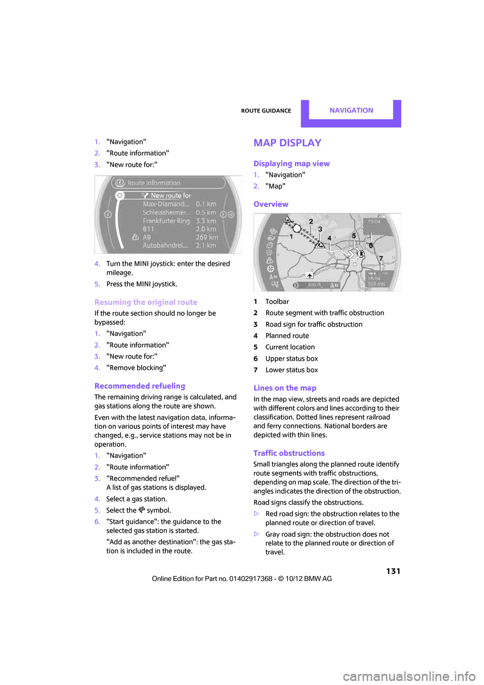
Overview
1Toolbar
2 Route segment with traffic obstruction
3 Road sign for traffic obstruction
4 Planned route
5 Current location
6 Upper status box
7 Lower status box
Lines on the map
In the map view, streets and roads are depicted
with different colors and lines according to their
classification. Dotted lines represent railroad
and ferry connections. National borders are
depicted with thin lines.
Traffic obstructions
Small triangles along the planned route identify
route segments with traffic obstructions,
depending on map scale. The direction of the tri-
angles indicates the dire ction of the obstruction.
Road signs classify the obstructions.
> Red road sign: the obstruction relates to the
planned route or direction of travel.
> Gray road sign: the obstruction does not
relate to the planned route or direction of
travel.
00320051004F004C00510048000300280047004C0057004C005200510003
Page 201 of 275
MOBILITYRefueling
200
Refueling
Vehicle equipment
In this chapter, all production, country, and
optional equipment that is offered in the model
range is described. Equipment is also described
that is not available because of, for example,
selected options or coun try version. This also
applies to safety relate d functions and systems.
General information
Switch off the engine before refueling;
otherwise, fuel cannot be added to the
tank and a message will be displayed. <
Take all precautionary measures and
observe all applicable regulations when
handling fuel. Do not carry any spare fuel con-
tainers in your vehicle. They can develop a leak
and cause an explosion or cause a fire in the
event of an accident. <
Fuel filler flap
Opening
MINI Countryman: MINI Paceman:
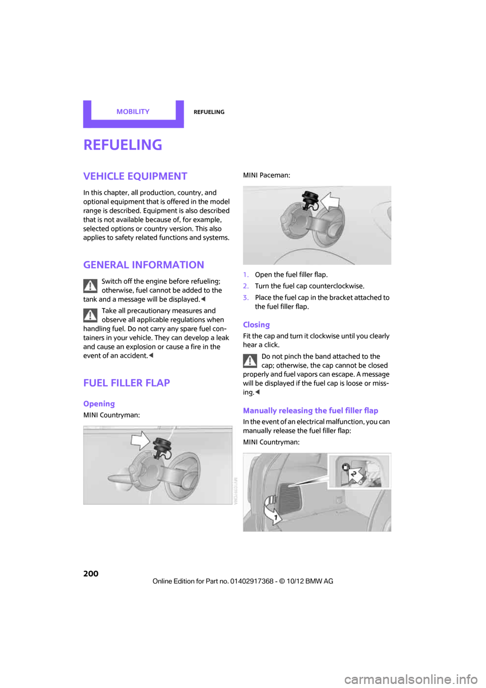
1.
Open the fuel filler flap.
2. Turn the fuel cap counterclockwise.
3. Place the fuel cap in the bracket attached to
the fuel filler flap.
Closing
Fit the cap and turn it clockwise until you clearly
hear a click.
Do not pinch the band attached to the
cap; otherwise, the ca p cannot be closed
properly and fuel vapors can escape. A message
will be displayed if the fuel cap is loose or miss-
ing. <
Manually releasing the fuel filler flap
In the event of an electrical malfunction, you can
manually release the fuel filler flap:
MINI Countryman:
00320051004F004C00510048000300280047004C0057004C005200510003
Page 216 of 275
Engine compartmentMOBILITY
215
Hood
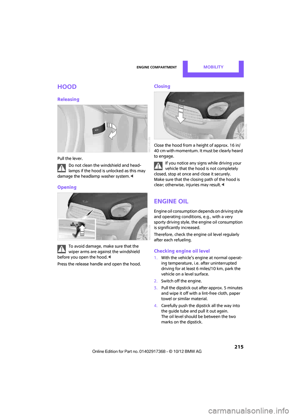
Releasing
Pull the lever.Do not clean the windshield and head-
lamps if the hood is unlocked as this may
damage the headlamp washer system. <
Opening
To avoid damage, make sure that the
wiper arms are against the windshield
before you open the hood. <
Press the release handle and open the hood.
Closing
Close the hood from a height of approx. 16 in/
40 cm with momentum. It must be clearly heard
to engage. If you notice any signs while driving your
vehicle that the hood is not completely
closed, stop at once and close it securely.
Make sure that the closing path of the hood is
clear; otherwise, injuries may result. <
Engine oil
Engine oil consumption depends on driving style
and operating conditions, e.g., with a very
sporty driving style, the engine oil consumption
is significantly increased.
Therefore, check the engine oil level regularly
after each refueling.
Checking engine oil level
1. With the vehicle's engi ne at normal operat-
ing temperature, i.e. after uninterrupted
driving for at least 6 miles/10 km, park the
vehicle on a level surface.
2. Switch off the engine.
3. Pull the dipstick out after approx. 5 minutes
and wipe it off with a lint-free cloth, paper
towel or similar material.
4. Carefully push the dipstick all the way into
the guide tube and pull it out again.
The oil level should be between the two
marks on the dipstick.
00320051004F004C00510048000300280047004C0057004C005200510003
Page 218 of 275
Engine compartmentMOBILITY
217
Oil change
Only MINI dealers are to perform oil changes.
Coolant
Coolant consists of half water and half additive.
Not all commercially available additives are suit-
able for your MINI. Your MINI dealer knows
which additives are suitable and will be glad to
advise you.Only use suitable additives; otherwise,
engine damage may result. Because addi-
tives are harmful to your health, it is important
to follow the instructions on the containers. <
Comply with the appropriate environmen-
tal protection regulations when disposing
of coolant additives. <
Coolant temperature
A warning lamp will come on if the coolant, and
therefore the engine, becomes too hot.
A message appears on the Control Display.
Checking coolant level
Do not add coolant to the cooling system
when the engine is hot. Escaping coolant
can cause burns. <
Do not open the hood until the engine has
cooled down.
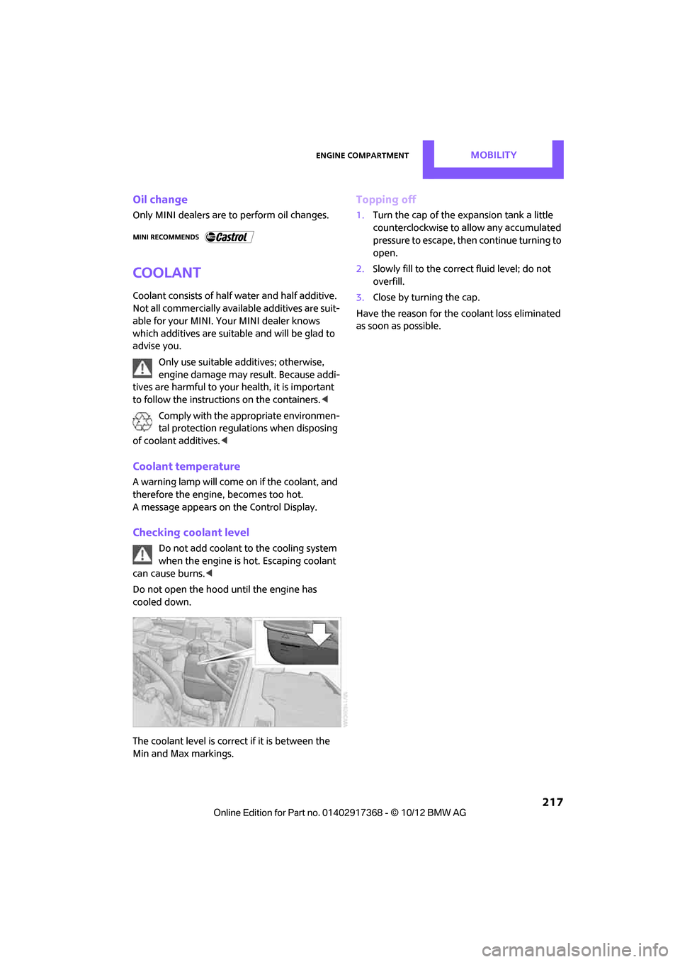
The coolant level is correct if it is between the
Min and Max markings.
Topping off
1. Turn the cap of the expansion tank a little
counterclockwise to allow any accumulated
pressure to escape, then continue turning to
open.
2. Slowly fill to the correct fluid level; do not
overfill.
3. Close by turning the cap.
Have the reason for the coolant loss eliminated
as soon as possible.
00320051004F004C00510048000300280047004C0057004C005200510003
Page 222 of 275
CareMOBILITY
221
>Remove additional atta chments, e.g. spoil-
ers or telephone antennas, if there is a pos-
sibility that they could be damaged.
> Insert the remote cont rol into the ignition
lock.
Automatic transmission
Before driving into the ca r wash, make sure that
the vehicle can roll:
1. Place the remote control, even with Comfort
Access, in the ig nition lock.
2. Move the selector lever to position N.
3. Release the parking brake.
4. Switch off the engine.
5. Insert the remote control in the ignition lock
so that the vehicle can roll.
Steam jets/high-pressure washers
When using steam jets or high-pressure
washers, make sure th at you maintain suf-
ficient distance from the vehicle and do not
exceed a maximum temperature of 140 7/
60 6 .
If the distance is too close, the pressure too high,
or the temperature too high, parts of the vehicle
can be damaged, or water can penetrate.
Observe the operating in structions for high-
pressure washers. <
Do not spray sensors such as the Park Dis-
tance Control with hi gh-pressure washers
for a long time and main tain the greatest possi-
ble distance of approx. 1 ft/30 cm from them. <
Manual washing
Use a great deal of water and, if necessary, car
shampoo when washing your car by hand. Clean
the vehicle with a sponge or a washing brush
applying a slight amount of pressure.
Before cleaning the windshield, deacti-
vate the rain sensor or turn off the ignition
to prevent unintentional wiping.
ing vehicles by hand. <
Headlamps
Do not wipe dry and do not use abrasive or cor-
rosive cleaning agents. Remove dirt and con-
tamination, such as inse cts, by soaking with
shampoo and then washing with plenty of
water.
Do not remove accumula ted ice and snow with
an ice scraper; use window deicers instead.
Windows
Clean the outside and inside of the windows and
mirrors with a window cleaner.
Do not clean the mirro rs with cleaners
containing quartz. <
Wiper blades
Clean with soapy water an d change regularly to
prevent the formation of streaks.
Wax, preservatives and dirt on the win-
dows cause streaks when the windshield
wipers are on, and can cause premature wear of
the wiper blades and interfere with the rain sen-
sor.<
Paintwork, care
Regular care helps your vehicle retain its value
and protects the pain t from the long-term
effects of aggressive substances.
Environmental influences in areas with
increased air pollution or natural contaminants,
such as tree sap or pollen, can affect the vehicle
paintwork. It is therefor e important to adjust the
frequency and extent of vehicle care corre-
spondingly.
Immediately remove any pa rticularly aggressive
substances, such as fuel that has overflowed, oil,
grease, brake fluid, or bi rd droppings; otherwise,
paint damage can be caused.
00320051004F004C00510048000300280047004C0057004C005200510003
Page 225 of 275
MOBILITYReplacing components
224
Replacing components
Vehicle equipment
In this chapter, all production, country, and
optional equipment that is offered in the model
range is described. Equipment is also described
that is not available because of, for example,
selected options or coun try version. This also
applies to safety relate d functions and systems.
Wiper blades
Do not place windshield wipers on the
windshield if wiper blades are not
installed; otherwise, the windshield may be
damaged. <
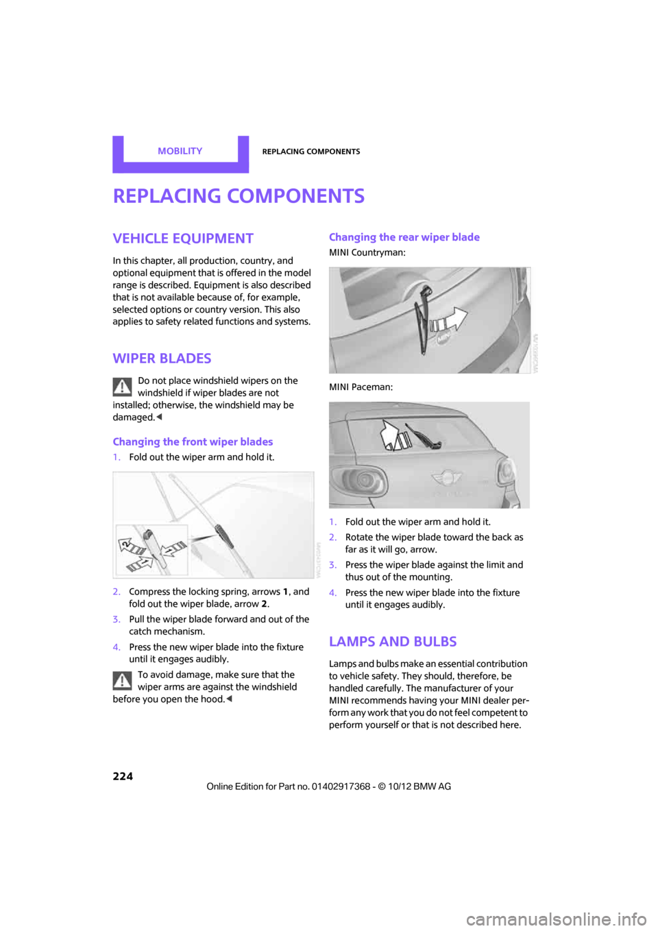
Changing the front wiper blades
1.Fold out the wiper arm and hold it.
2. Compress the locking spring, arrows 1, and
fold out the wiper blade, arrow 2.
3. Pull the wiper blade forward and out of the
catch mechanism.
4. Press the new wiper blade into the fixture
until it engages audibly.
To avoid damage, make sure that the
wiper arms are against the windshield
before you open the hood. <
Changing the rear wiper blade
MINI Countryman:
MINI Paceman:
1.Fold out the wiper arm and hold it.
2. Rotate the wiper blade toward the back as
far as it will go, arrow.
3. Press the wiper blade against the limit and
thus out of the mounting.
4. Press the new wiper blade into the fixture
until it engages audibly.
Lamps and bulbs
Lamps and bulbs make an essential contribution
to vehicle safety. They should, therefore, be
handled carefully. The manufacturer of your
MINI recommends having your MINI dealer per-
form any work that you do not feel competent to
perform yourself or that is not described here.
00320051004F004C00510048000300280047004C0057004C005200510003
Page 227 of 275
MOBILITYReplacing components
226
Accessing the lamp from the engine
compartment
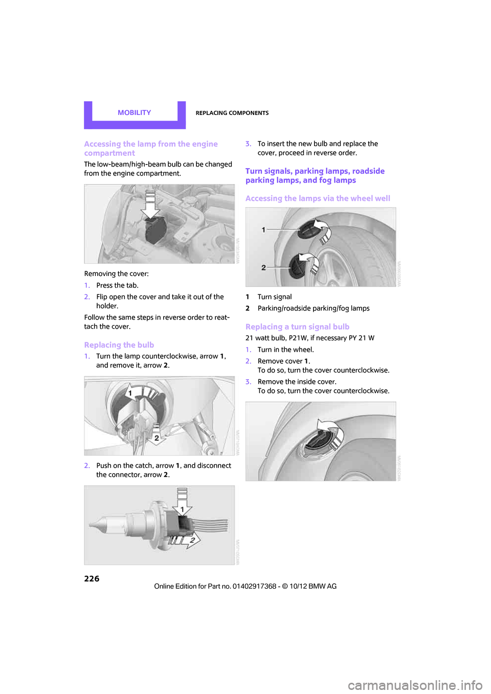
The low-beam/high-beam bulb can be changed
from the engine compartment.
Removing the cover:
1.Press the tab.
2. Flip open the cover and take it out of the
holder.
Follow the same steps in reverse order to reat-
tach the cover.
Replacing the bulb
1. Turn the lamp counterclockwise, arrow 1,
and remove it, arrow 2.
2. Push on the catch, arrow 1, and disconnect
the connector, arrow 2. 3.
To insert the new bulb and replace the
cover, proceed in reverse order.
Turn signals, parking lamps, roadside
parking lamps, and fog lamps
Accessing the lamps via the wheel well
1Turn signal
2 Parking/roadside parking/fog lamps
Replacing a turn signal bulb
21 watt bulb, P21W, if necessary PY 21 W
1.Turn in the wheel.
2. Remove cover 1.
To do so, turn the cover counterclockwise.
3. Remove the inside cover.
To do so, turn the cover counterclockwise.
00320051004F004C00510048000300280047004C0057004C005200510003