relay MITSUBISHI 3000GT 1991 Owners Manual
[x] Cancel search | Manufacturer: MITSUBISHI, Model Year: 1991, Model line: 3000GT, Model: MITSUBISHI 3000GT 1991Pages: 1146, PDF Size: 76.68 MB
Page 875 of 1146
BODY - SDecifications
L
)
L
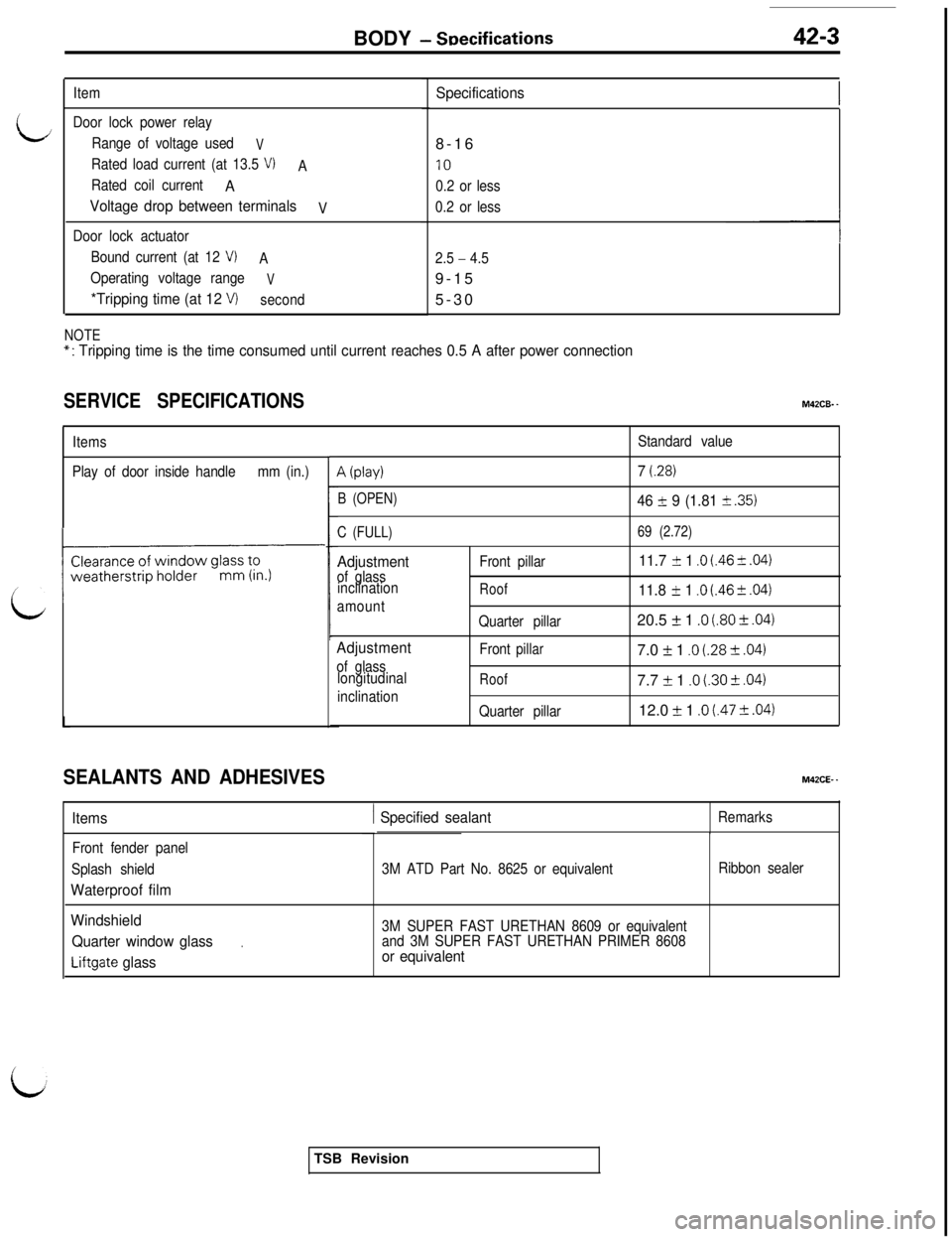
Item
Door lock power relay
Range of voltage used
V
Rated load current (at 13.5 VIA
Rated coil current
A
Voltage drop between terminals
V
Door lock actuator
Bound current (at 12
V)A
Operating voltage range
V
*Tripping time (at 12 VIsecond
Specifications8-16
IO
0.2 or less
0.2 or less
2.5
- 4.59-15
5-30
NOTE*: Tripping time is the time consumed until current reaches 0.5 A after power connection
SERVICE SPECIFICATIONSM42CB. -
ItemsStandard value
Play of door inside handlemm (in.)
A (play)
B (OPEN)
C (FULL)
Adjustmentof glass
inclination
amountFront pillarRoof
7 (.28)
46 f 9 (1.81 31 .35)
69 (2.72)
11.7 I!I 1 .O (.46 ?I .04)
11.8 f 1 .O (.46 + ,041L
SEALANTS AND ADHESIVES
Adjustment
of glass
longitudinal
inclinationQuarter pillar
Front
pillar
Roof
Quarter pillar20.5
f 1 .O (.80 f .04)7.0
i 1 .O (.28 -+ ,0417.7
If: 1 .o i.30 5 ,04112.0
f 1 .o I.47 + .04)
M42CE- -
Items1 Specified sealantRemarks
Front fender panel
Splash shield
Waterproof film
3M ATD Part No. 8625 or equivalentRibbon sealer
Windshield3M SUPER FAST URETHAN 8609 or equivalentQuarter window glass.and 3M SUPER FAST URETHAN PRIMER 8608
Liftgate glassor equivalentTSB Revision
Page 879 of 1146
BODY - Troubleshooting42-7
i
/
I/
i
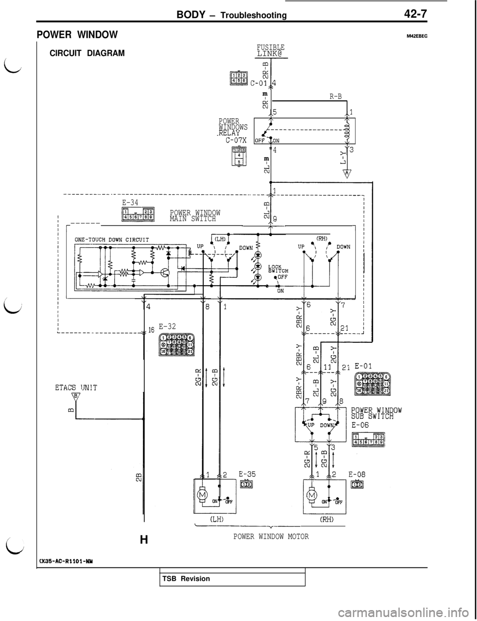
POWER WINDOW
CIRCUIT DIAGRAMFUSIBLELINK@
POWERWINDOWS.RELAYC-07Xm
IR-B
%,,5,,l,\/\
-__------------
v
"43m
I,:
2F7
IIIII/IIIIIII,IIIIIIIIIIIII
_____ ---._-- .----------------------------- ----. ---
E-34
POWER WINDOW
MAIN SWITCH
------1r
L-
ETACS IJNIT
16 E-32
(RH)
(LH)(RH)----v--H
POWER WINDOW MOTOR
Page 880 of 1146
![MITSUBISHI 3000GT 1991 Owners Manual 42-8BODY - Troubleshooting
SWITCH(IG1)
‘dPOWER
WINDOWS
RELAY
J,B , "C-68&.p ,i,p ii@i/
JUMPER
CONNECTOR
r---- --.-- -_----_---_
11 ,i*;iv
_---___-_----___;i3 Xl
0
5/\
c!J
A,
I
tc-34 __pEEL!E]
c
d>
1 MITSUBISHI 3000GT 1991 Owners Manual 42-8BODY - Troubleshooting
SWITCH(IG1)
‘dPOWER
WINDOWS
RELAY
J,B , "C-68&.p ,i,p ii@i/
JUMPER
CONNECTOR
r---- --.-- -_----_---_
11 ,i*;iv
_---___-_----___;i3 Xl
0
5/\
c!J
A,
I
tc-34 __pEEL!E]
c
d>
1](/img/19/57085/w960_57085-879.png)
42-8BODY - Troubleshooting
SWITCH(IG1)
‘dPOWER
WINDOWS
RELAY
J,B , "C-68&.p ,i,p ii@i/
JUMPER
CONNECTOR
r---- --.-- -_----_---_
11 ,i*;iv
_---___-_----___;i3 Xl
0
5/\
c!J
A,
I
tc-34 __pEEL!E]
c
d>
1
GNDn
-4-----;7x1;g*2\L4,j4
”. . ..--- --___--__
:I
14%l1oy2
7 I
=-
SELF-DIAGNOSISCHECK C01'6NZCTORE-21
1 mr
(RH)(LH)
DooR TWITCHTSB Revision
Page 881 of 1146
BODY - Troubleshooting42-9
OPERATION
0
I/
0
0
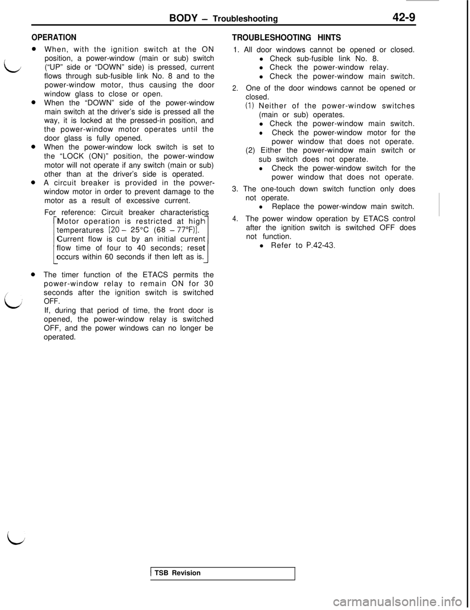
0When, with the ignition switch at the ON
position, a power-window (main or sub) switch
(“UP” side or “DOWN” side) is pressed, current
flows through sub-fusible link No. 8 and to the
power-window motor, thus causing the door
window glass to close or open.
When the “DOWN” side of the power-window
main switch at the driver’s side is pressed all the
way, it is locked at the pressed-in position, and
the power-window motor operates until the
door glass is fully opened.
When the power-window lock switch is set to
the “LOCK (ON)” position, the power-window
motor will not operate if any switch (main or sub)
other than at the driver’s side is operated.
A circuit breaker is provided in the power-window motor in order to prevent damage to the
motor as a result of excessive current.
For reference: Circuit breaker characteristics
Motor operation is restricted at high
temperatures
:
[20 - 25°C (68 - 77”F)].Current flow is cut by an initial current
occurs within 60 seconds if then left as
Iflow time of four to 40 seconds; resetis.The timer function of the ETACS permits the
power-window relay to remain ON for 30
seconds after the ignition switch is switched
OFF.If, during that period of time, the front door is
opened, the power-window relay is switched
OFF, and the power windows can no longer be
operated.
TROUBLESHOOTING HINTS1. All door windows cannot be opened or closed.
l Check sub-fusible link No. 8.
l Check the power-window relay.
l Check the power-window main switch.
2.One of the door windows cannot be opened or
closed.
(1) Neither of the power-window switches
(main or sub) operates.
l Check the power-window main switch.
lCheck the power-window motor for the
power window that does not operate.
(2) Either the power-window main switch or
sub switch does not operate.
lCheck the power-window switch for the
power window that does not operate.
3. The one-touch down switch function only does
not operate.
lReplace the power-window main switch.
4.The power window operation by ETACS control
after the ignition switch is switched OFF does
not function.
l Refer to
P.42-43.
i
1 TSB Revision
Page 882 of 1146
42-10
BODY - Troubleshooting
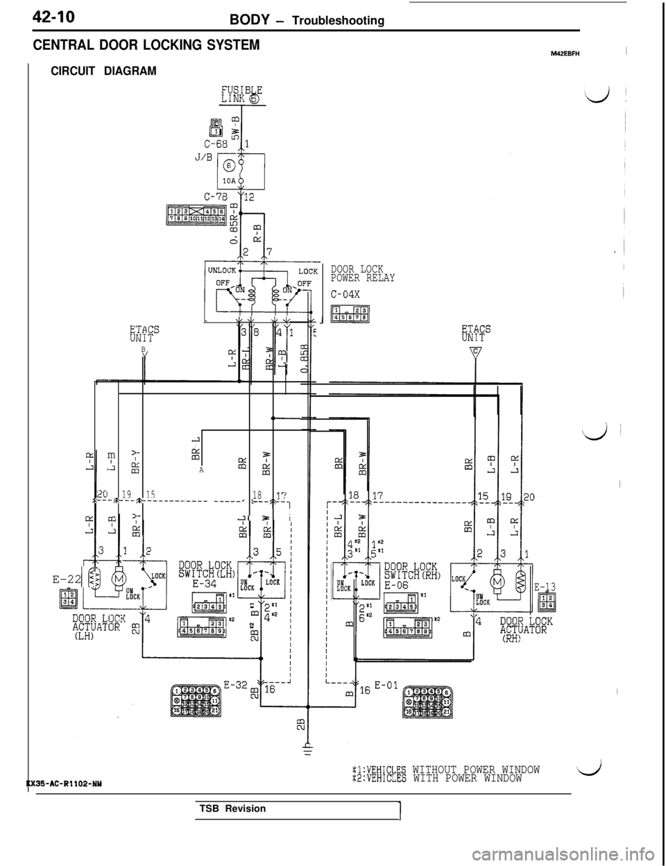
CENTRAL DOOR LOCKING SYSTEM
CIRCUIT DIAGRAM
E-22 2If
J/V .L.L
g:s
B
,-4
Im
>;E
*Al g7=A%Ei
2019151817,---~~--~~-------.---- _____I ,--,L-,
ILIZ=I
35-AC-Rll02-NU
M42EBFHI
DOOR LOCK
POWER RELAY
J
E-13
%l:VEHICLES WITHOUT POWER WINDOWX2:VEHICLES WITH POWER WINDOW
\,3~
I
I
>dTSB RevisionI
Page 883 of 1146
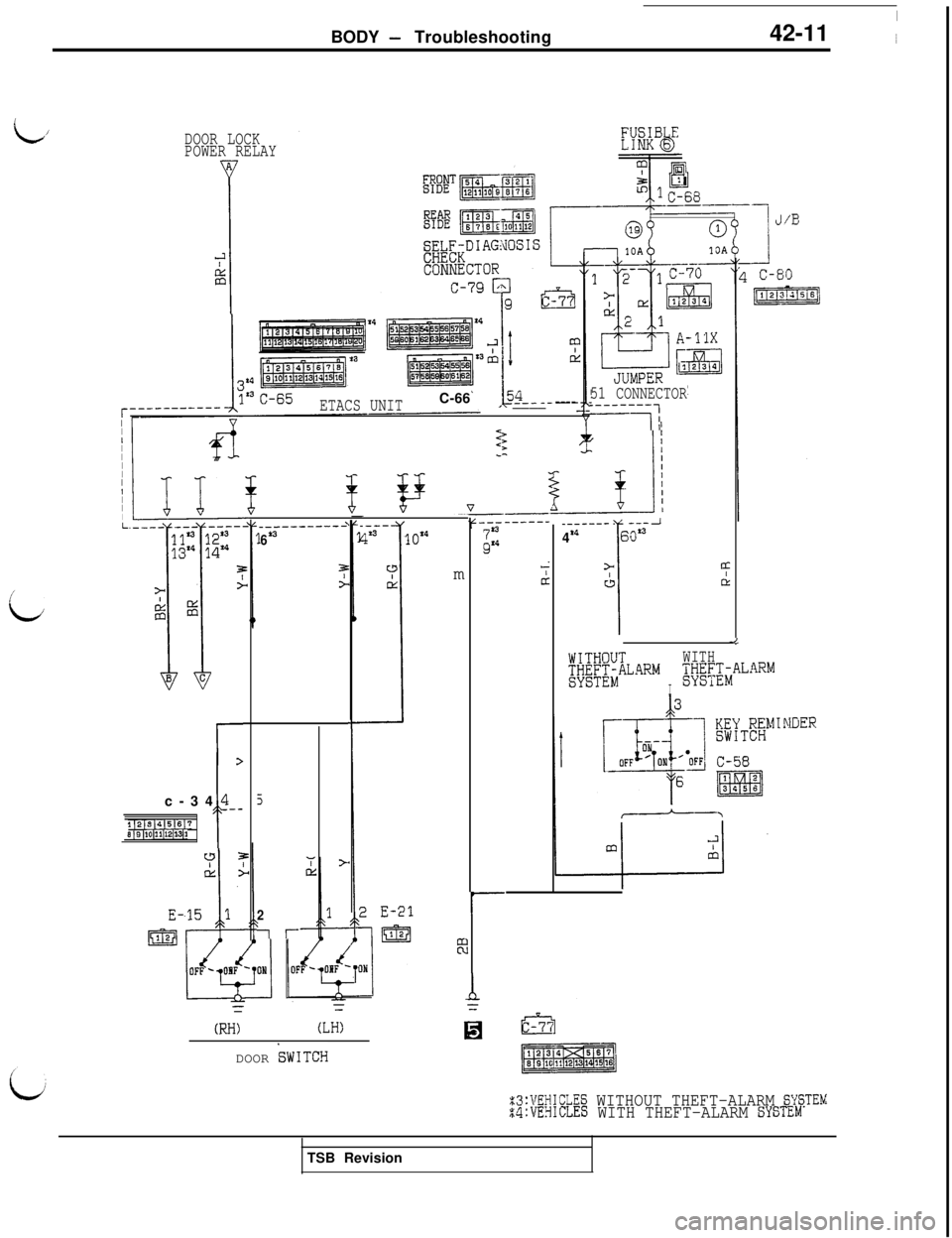
BODY - TroubleshootingI
42-11 ~
L/DOOR LOCK
POWER RELAY
A
I
2
Ei
J/E
51 CONNECTOR_--____-
-11
ETACS UNITC-66
____ ----____-----_-i-
I>22
II
I
I
I
I
II
I
I
IL____--- ----I
41460s3
>
I
s
CLd
_---
4*310X4
Tci
It
----------L
6*3m
i
-I
[#&iLARM
I
WITH;t;Z;iALARMI
I3
5
2
ir-c-34
4--
112~3~4~5(6~7E 19 ~10~11~12~13[1f
I-
Z3:VEHICLES WITHOUT THEFT-ALARM SYSTEMs4:VEHICLES WITH THEFT-ALARM SYSTLM
N-I)(LH:DOOR
TWITCHTSB Revision
Page 884 of 1146
42-12
BODY - Troubleshooting
OPERATIONl When the door lock switch is set to the LOCK side (or
UNLOCK side), the LOCK side (or UNLOCK side) of the
door lock relay is turned ON and the door actuators of
alIsadoors operate.
lIf the driver seat side door (or assistant seat side door) is
opened and the driver seat side inside lock knob (or
assistant seat side inside lock knob) is locked with the key
inserted in the ignition switch, the ETACS unit grounds the
unlock side circuit of the door lock relay to unlock all doors.
This way, failure to remove the key is prevented.
NOTEThe door lock actuator contains a PTC thermister to prevent
damage caused by overheating of the motor. If the central
door lock is frequently used, the actuator may temporarily
fail to operate. If it returns to normal in a few minutes, it is
not defective.
TROUBLESHOOTING HINTS
1. One of the door lock actuators fails to operate.
l Check the door actuator which fails to operate.
2. The ignition key reminder system does not function.
l For information concerning ETACS control, refer to
P.42-55.
Page 915 of 1146
BODY - Power Window42-43
/;i
$
Diagnosis connector-Gr&nd
ETkCS ‘6R”38
Nith voltmeter-.___
1Withmulti-use tester
POWER WINDOWM42MHAH
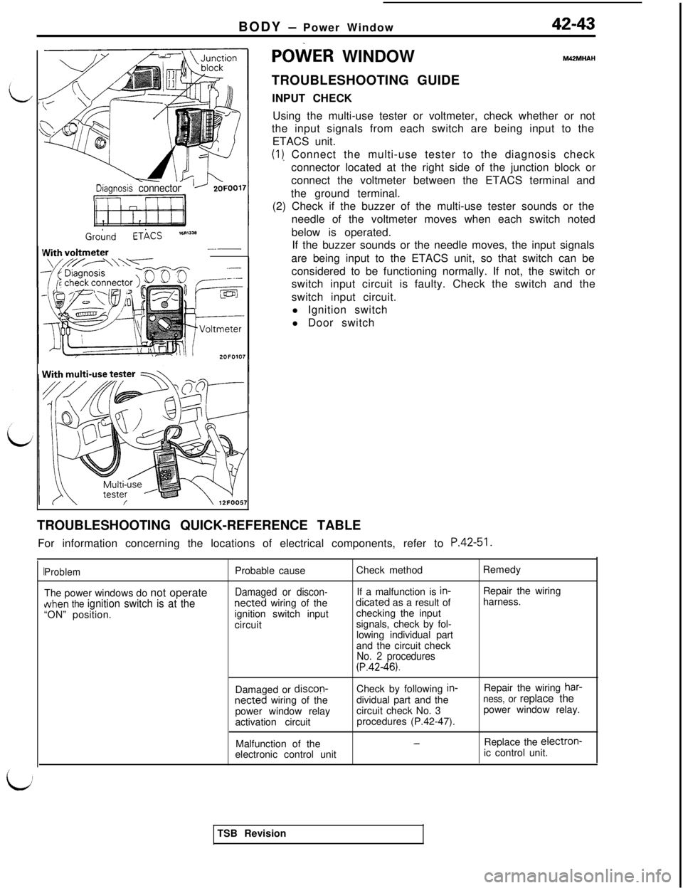
TROUBLESHOOTING GUIDE
INPUT CHECK
Using the multi-use tester or voltmeter, check whether or not
the input signals from each switch are being input to the
ETACS unit.
(I), Connect the multi-use tester to the diagnosis check
connector located at the right side of the junction block or
connect the voltmeter between the ETACS terminal and
the ground terminal.
(2) Check if the buzzer of the multi-use tester sounds or the
needle of the voltmeter moves when each switch noted
below is operated.
If the buzzer sounds or the needle moves, the input signals
are being input to the ETACS unit, so that switch can be
considered to be functioning normally. If not, the switch or
switch input circuit is faulty. Check the switch and the
switch input circuit.
l Ignition switch
l Door switch
TROUBLESHOOTING QUICK-REFERENCE TABLE
For information concerning the locations of electrical components, refer to
P.42-51.
ProblemThe power windows do not operateNhen
the ignition switch is at the“ON” position.Probable cause
Damaged or discon-netted wiring of the
ignition switch input
circuitCheck method
If a malfunction is in-dicated as a result of
checking the input
signals, check by fol-
lowing individual part
and the circuit check
No. 2 procedures(P.42-46).Remedy
Repair the wiring
harness.
Damaged or discon-Check by following
in-Repair the wiring har-
netted wiring of thedividual part and theness, or replace thepower window relaycircuit check No. 3power window relay.
activation circuitprocedures (P.42-47).
Malfunction of the
-Replace the electron-electronic control unitic control unit.
TSB Revision
Page 916 of 1146
42-44
BODY - Power Window
Problem
Probable causeCheck method
Remedy
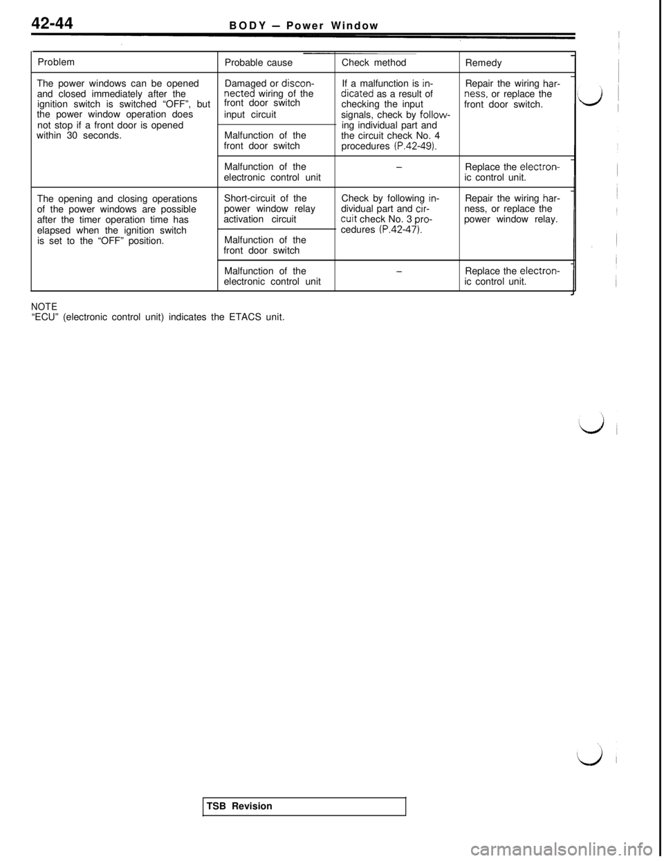
The power windows can be opened
and closed immediately after theDamaged or discon-If a malfunction is
in-netted wiring of thedicated as a result ofRepair the wiring har-ignition switch is switched “OFF”, butfront door switch
checking the inputness. or replace the
the power window operation doesfront door switch.
not stop if a front door is openedinput circuit
signals, check by
follow-within 30 seconds.Malfunction of theing individual part and
the circuit check No. 4
front door switch
procedures
(P.42-49).Malfunction of the
-electronic control unitReplace the electron-ic control unit.
The opening and closing operations
of the power windows are possible
after the timer operation time has
elapsed when the ignition switch
is set to the “OFF” position.Short-circuit of the
power window relay
activation circuit
Malfunction of the
front door switchCheck by following
in-dividual part and cir-cuit check No. 3
pro-cedures (P.42-47).Repair the wiring
har-ness, or replace the
power window relay.
Malfunction of the
electronic control unit
-Replace the electron-ic control unit.
NOTE“ECU” (electronic control unit) indicates the ETACS unit.
TSB Revision
Page 919 of 1146
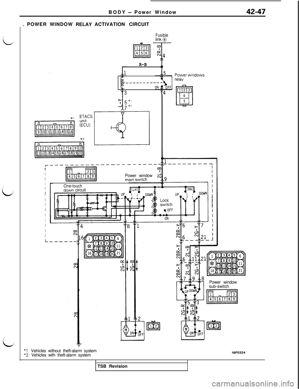
BODY - Power Window
;. POWERWINDOW
RELAYACTIVATION CIRCUIT
Fusiblelink @
R-B0
&5
____-------
y3"4
I
I
I
II
I
II
I
I
I
I
I
I
----------_-__---
Power window
One-touchdnwn circuit
L-
*I : Vehicles without theft-alarm system“2: Vehicles with theft-alarm systemPower window
sub-switch16FO324TSB Revision