ECO mode MITSUBISHI 3000GT 1991 User Guide
[x] Cancel search | Manufacturer: MITSUBISHI, Model Year: 1991, Model line: 3000GT, Model: MITSUBISHI 3000GT 1991Pages: 1146, PDF Size: 76.68 MB
Page 738 of 1146
![MITSUBISHI 3000GT 1991 User Guide 35-16SERVICE BRAKES -Anti-lock Braking System Troubleshooting
BABS warning light stays on when the ignition key is in the “ON” position.
[Explanation]
[Hint]
This is the symptom when the ABS ECU d MITSUBISHI 3000GT 1991 User Guide 35-16SERVICE BRAKES -Anti-lock Braking System Troubleshooting
BABS warning light stays on when the ignition key is in the “ON” position.
[Explanation]
[Hint]
This is the symptom when the ABS ECU d](/img/19/57085/w960_57085-737.png)
35-16SERVICE BRAKES -Anti-lock Braking System Troubleshooting
BABS warning light stays on when the ignition key is in the “ON” position.
[Explanation]
[Hint]
This is the symptom when the ABS ECU does not
Check the diagnosis output and if there is no output
power up due to broken ECU power circuit, etc.,
voltage or if the MUT and ABS ECU cannot
when the fail safe function operates and isolates thecommunicate, there is a good possibility that power
system or when the warning light drive circuit is
is not flowing to the ECU.
short circuited.
!8IGNIISWIT(-
:Et
J’B @
C151
:
E
COMBINATION
METER
-19
7
------____-_---1
2
610 2
~;@lizEFgIIc,
6227J
r bL-1
IN(IGl)
1
,
ig
)
158
7
r-TSB iCaution
lIf the trouble code is output, the system can
be in the fail safe mode. in such a case, erase
the trouble code and then restart the engine
to check if the system is currently in a fault
condition.
~~~~
~~~~1
I,No ,I
Yes6
Replace ECU.
41,No rIDoes the ABS warning light
remain illuminated even with
the HU connector discon-
nected?
Yes
Short-circuit in harness
between HU or ECU and ABS
warning light
> Repair harness or replace
combination meter.
bvision
Page 780 of 1146
35-58SERVICE BRAKES - Service Adjustment Procedures
POINTS IN WAVEFORM MEASUREMENT
Symptom
Too small or zero waveform
amplitudeProbable causes
Faulty wheel speed sensorRemedy
Replace sensor
Incorrect pole piece-to-rotor clearance
Adjust clearance
Waveform amplitude fluctuates
excessively (this is no problem ifAxle hub eccentric or with large runout
Replace hub
the minimum amplitude is
100 mV
or more)
Noisy or disturbed waveformOpen circuit in sensor
Open circuit in harness
Incorrectly mounted wheel speed sensor
Rotor with missing or damaged teethReplace sensor
Correct harness
Mount correctly
Replace rotor
NOTEThe wheel speed sensor cable moves following motion of the front or rear suspension. Therefore, it is likely that it has an
open circuit only when driving on rough roads and it functions normally on ordinary roads. It is, therefore, recommended
to observe sensor output voltage waveform also under special conditions, such as rough road driving,
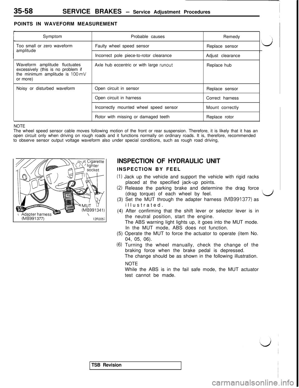
(ME!991 377)12FOO5i
INSPECTION OF HYDRAULIC UNITINSPECTION BY FEEL
(I) Jack up the vehicle and support the vehicle with rigid racks
placed at the specified jack-up points.
(2) Release the parking brake and determine the drag force
(drag torque) of each wheel by feel.
LJ(3) Set the MUT through the adapter harness (MB991377) as
illustrated.
(4) After confirming that the shift lever or selector lever is in
the neutral position, start the engine.
The ABS warning light lights up, it goes into the MUT mode.
In the MUT mode, ABS does not function.
(5) Operate the MUT to force the actuator to operate (item No.
04, 05, 06).
(6) Turning the wheel manually, check the change of the
braking force when the brake pedal is depressed.
The change should be as shown in the following illustration.
NOTEWhile the ABS is in the fail safe mode, the MUT actuator
test cannot be made.
TSB Revision
Page 1012 of 1146
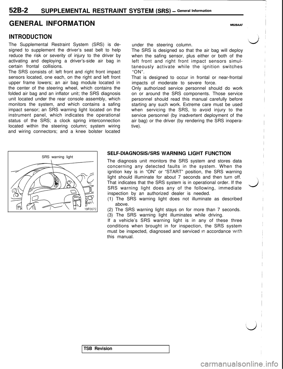
52B-2SUPPLEMENTAL RESTRAINT SYSTEM (SRS) - General informationGENERAL INFORMATION
INTRODUCTIONThe Supplemental Restraint System (SRS) is de-
signed to supplement the driver’s seat belt to help
reduce the risk or severity of injury to the driver by
activating and deploying a driver’s-side air bag in
certain frontal collisions.
The SRS consists of: left front and right front impact
sensors located, one each, on the right and left front
upper frame lowers; an air bag module located in
the center of the steering wheel, which contains the
folded air bag and an inflator unit; the SRS diagnosis
unit located under the rear console assembly, which
monitors the system, and which contains a safing
impact sensor; an SRS warning light located on the
instrument panel, which indicates the operational
status of the SRS; a clock spring interconnection
located within the steering column; system wiring
and wiring connectors; and a knee bolster located
SRS warning light
M52BAAFunder the steering column.
The SRS is designed so that the air bag will deploy
when the safing sensor, plus either or both of the
left front and right front impact sensors simul-
taneously activate while the ignition switches
“ON”.
That is designed to occur in frontal or near-frontal
impacts of moderate to severe force.
Only authorized service personnel should do work
on or around the SRS components. Those service
personnel should read this manual carefully before
starting any such work. Extreme care must be used
whenservicing the SRS, to avoid injury to the
service personnel (by inadvertent deployment of the
air bag) or the driver (by rendering the SRS inopera-
tive).
SELF-DIAGNOSIS/SRS WARNING LIGHT FUNCTION
The diagnosis unit monitors the SRS system and stores data
concerning any detected faults in the system. When the
ignition key is in “ON” or “START” position, the SRS warning
light should illuminate for about 7 seconds and then turn off.
That indicates that the SRS system is in operational order. If the
SRS warning light does any of the following, immediate
inspection by an authorized dealer is needed.
(1) The SRS warning light does not illuminate as described
above.
(2) The SRS warning light stays on for more than 7 seconds.
(3) The SRS warning light illuminates while driving.
If a vehicle’s SRS warning light is in any of these three
conditions when brought in for inspection, the SRS system
must be inspected, diagnosed and serviced
In accordance wrth
this manual.
TSB Revision
Page 1028 of 1146
52B-18 SUPPLEMENTAL RESTRAINT SYSTEM (SRS) - Troubleshooting
DIAGNOSTIC SEQUENCE
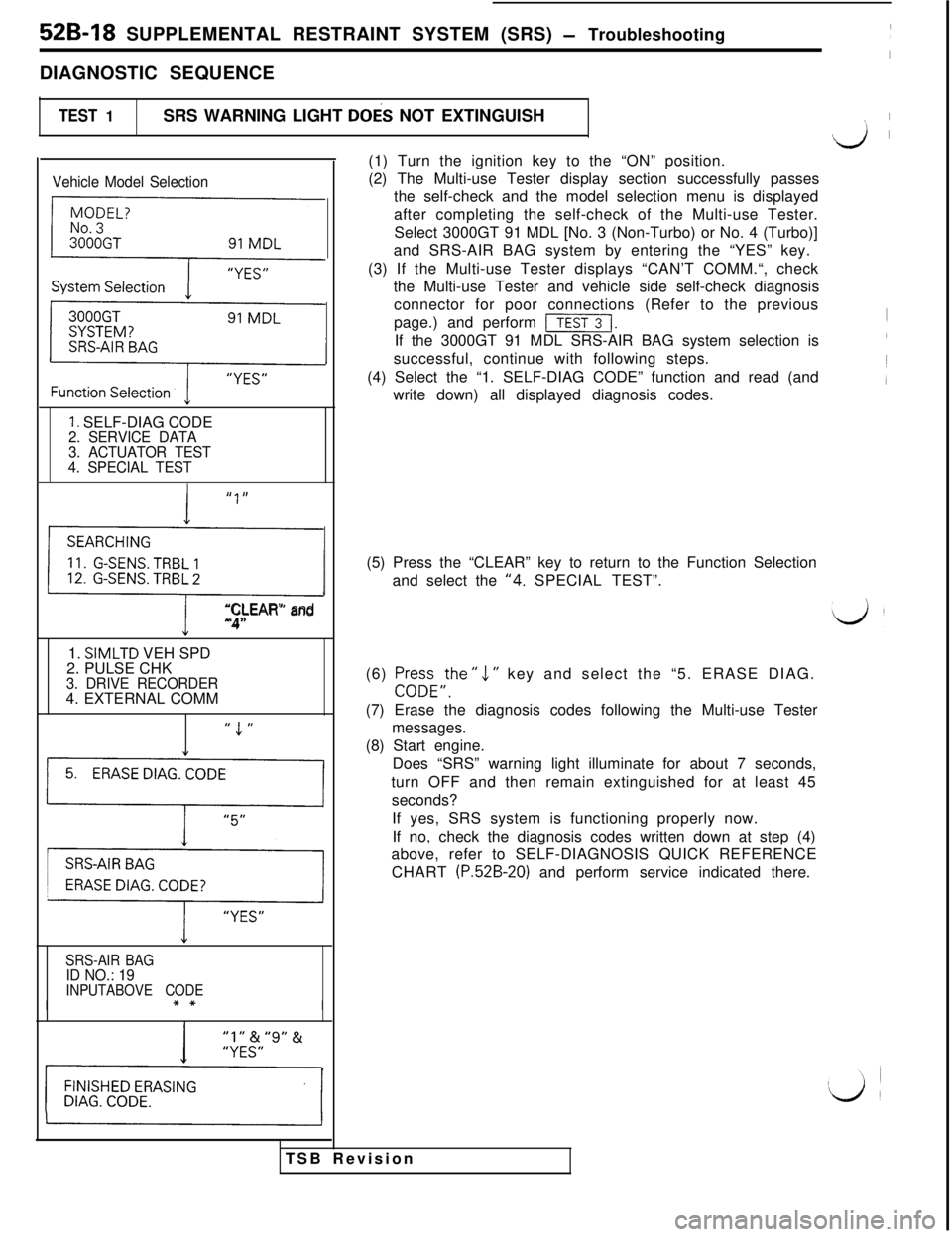
TEST 1SRS WARNING LIGHT DOES NOT EXTINGUISH
\1 I
Vehicle Model Selection
{
F
1. SELF-DIAG CODE2. SERVICE DATA
3. ACTUATOR TEST
4. SPECIAL TEST
,, I,
0
“CLEAR” and“4”1.
SIMLTD VEH SPD
2. PULSE CHK
3. DRIVE RECORDER4. EXTERNAL COMM
” 1 ”
1’1
y,,
SRS-AIR BAGID NO.: 19INPUTABOVE CODE
I(1) Turn the ignition key to the “ON” position.
(2) The Multi-use Tester display section successfully passes
the self-check and the model selection menu is displayed
after completing the self-check of the Multi-use Tester.
Select 3000GT 91 MDL [No. 3 (Non-Turbo) or No. 4 (Turbo)]
and SRS-AIR BAG system by entering the “YES” key.
(3) If the Multi-use Tester displays “CAN’T COMM.“, check
the Multi-use Tester and vehicle side self-check diagnosis
TSB Revisionconnector for poor connections (Refer to the previous
page.) and perform
[I.If the 3000GT 91 MDL SRS-AIR BAG system selection is
successful, continue with following steps.
(4) Select the “1. SELF-DIAG CODE” function and read (and
write down) all displayed diagnosis codes.
(5) Press the “CLEAR” key to return to the Function Selection
and select the
“4. SPECIAL TEST”.
(6) Pr+FE,the ”
1 ” key and select the “5. ERASE DIAG.
(7) Erase the diagnosis codes following the Multi-use Tester
messages.
(8) Start engine.
Does “SRS” warning light illuminate for about 7 seconds,
turn OFF and then remain extinguished for at least 45
seconds?
If yes, SRS system is functioning properly now.
If no, check the diagnosis codes written down at step (4)
above, refer to SELF-DIAGNOSIS QUICK REFERENCE
CHART
(P.52B-20) and perform service indicated there.
Page 1030 of 1146
![MITSUBISHI 3000GT 1991 User Guide 52B-20 SUPPLEMENTAL RESTRAINT SYSTEM (SRS) - Troubleshooting
SELF-DIAGNOSIS QUICK REFERENCE CHART
Fault
No.
-
11
32
Diagnosis code name
[Failure mode]
(NORMAL)
G-SENS. TRBL
1[Short circuit]
G-SENS. T MITSUBISHI 3000GT 1991 User Guide 52B-20 SUPPLEMENTAL RESTRAINT SYSTEM (SRS) - Troubleshooting
SELF-DIAGNOSIS QUICK REFERENCE CHART
Fault
No.
-
11
32
Diagnosis code name
[Failure mode]
(NORMAL)
G-SENS. TRBL
1[Short circuit]
G-SENS. T](/img/19/57085/w960_57085-1029.png)
52B-20 SUPPLEMENTAL RESTRAINT SYSTEM (SRS) - Troubleshooting
SELF-DIAGNOSIS QUICK REFERENCE CHART
Fault
No.
-
11
32
Diagnosis code name
[Failure mode]
(NORMAL)
G-SENS. TRBL
1[Short circuit]
G-SENS. TRBL 2[One open-circuit]
G-SENS. TRBL 3[Two open-circuit]
SQUIB TRBL 1[Short circuit]
SQUIB TRBL 2
[Open-circuit]
CONDENS. VO. HI
CONDENS. VO. LO
CRANKING TRBL
CONN. UNLOCKED
Explanation
Normal. The SRS is in goodorder.
The circuits for the front impact sensor are shortedto each other.
Right or left impact sensor cirucit is open or the
wire from the sensor to the SDU is open-circuit.
Right and left impact sensor circuits are open or thewires from the sensors to the SDU areopen-circuit.
The circuits for the air bag module (squib) are
shorted to each other or the circuit isgrounded.
The air bag module Isquib) circuit is open or the wire
from the air bag to the SDU (clock spring) is open-circuit.
The capacitor (integrated in the
SDU) terminal voltage
is higher than the specified value for 5 seconds.
The capacitor (integrated in the
SDU) terminal voltage
is lower than the specified value for 5 seconds.
The circuit for the cranking signal is shorted to
some power supply circuits.
It takes at least 45 seconds that the SDU detects
this fault.
The lock switch (short bar) of the SDU double lockconnector isopen.Service
Perform TEST 5
Perform TEST 6(I) Turn the ignition key
to the “LOCK” posi-
tion, disconnect the
negative battery
cable and tape the
terminal.
(2) After waiting atleast 30 seconds,
replace the SDU.
(Refer to P.52B-59.)
Perform TEST 7
Perform TEST 8NOTE
- IMPORTANT
(1) After repairing the SRS, reconnect the battery cable, erase the diagnosis code memory from theMulti-use Tester and check the SRS warning light operation to verify the system functions
properly. (Refer to TEST 1.)
(2) SDU
= SRS Diagnosis Unit
1 TSB Revision
Page 1031 of 1146
![MITSUBISHI 3000GT 1991 User Guide SUPPLEMENTAL RESTRAINT SYSTEM (SRS) - Troubleshooting 52B-21
/
id
FaultDiagnosis code nameNo.[Failure mode]Explanation
Service
41
IG VOLT LOW 1The multi-purpose fuse (No. 18) is blown or the wirefrom MITSUBISHI 3000GT 1991 User Guide SUPPLEMENTAL RESTRAINT SYSTEM (SRS) - Troubleshooting 52B-21
/
id
FaultDiagnosis code nameNo.[Failure mode]Explanation
Service
41
IG VOLT LOW 1The multi-purpose fuse (No. 18) is blown or the wirefrom](/img/19/57085/w960_57085-1030.png)
SUPPLEMENTAL RESTRAINT SYSTEM (SRS) - Troubleshooting 52B-21
/
id
FaultDiagnosis code nameNo.[Failure mode]Explanation
Service
41
IG VOLT LOW 1The multi-purpose fuse (No. 18) is blown or the wirefrom the fuse to the SDU is open-circuit or itsresistance value is increased.
It takes at least 5 seconds that the SDU detects
this fault.
Perform TEST 9
42
IG VOLT LOW 2The multi-purpose fuse (No. 11) is blown or the wirefrom the fuse to the SDU is open-circuit or itsresistance value is increased.
It takes at least 5 seconds that the SDU detects
this fault.
Perform TEST 10
SRS LMP TRBL 1
i
The SRS warning light circuits are open or the wireWhen SRS warning lightOpen circuit orfrom the light to the SDU is grounded.does not extinguish:43ground shortIIt takes at least 5 seconds with the light OFF thatPerform TEST 11the SDU detects this fault.When SRS warning light
does not illuminate:
Perform TEST 12
SRS LMP TRBL 2The SRS warning light drive transistor (integrated
(1) Turn the ignition key
44SRS warning light
[I
in the SDU) is open-circuit.to the “LOCK” posi-
drive transistortion, disconnet the
is open-circuitnegative battery
cable and tape the
SRS DIAG. UNITThe EEP ROM or A/D converter (integrated in the SDU)terminal.is defective.(2) After waiting at
45least 30 seconds,
replace the SDU.
(Refer to P.52B-59.)
/NOTE -IMPORTANT
b(1) After repairing the SRS, reconnect the battery cable, erase the diagnosis code memory from theMulti-use Tester and check the SRS warning light operation to verify the system functions
properly. (Refer to TEST 1.)
(2) SDU
= SRS Diagnosis Unit
1 TSB Revision
Page 1036 of 1146
52B-26 SUPPLEMENTAL RESTRAINT SYSTEM (SRS) - Troubleshooting
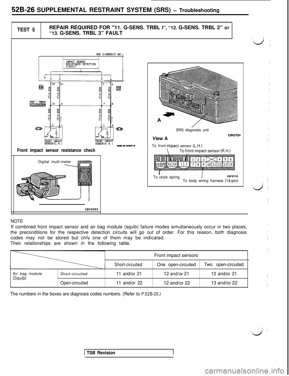
TEST 5REPAIR REQUIRED FOR "11. G-SENS. TRBL I”, “12. G-SENS. TRBL 2” or
“13. G-SENS. TRBL 3” FAULT
SRS DIAGNOSIS UN1
IMPACT S!NSOR~M&N"E DETECTION
FRONT IMPACTSENS0RtL.H.)FRONT IMPACTsEN80R(R. H. )--u-~,w-*
Front impact sensor resistance checkDigital multi-meter
r ~1iii”~“‘.,,,,/ ?\I. I,// q
NOTEIf combined front impact sensor and air bag module (squib) failure modes simultaneously occur in two places,
the preconditions for the respective detection circuits will go out of order. For this reason, both diagnosis
codes may not be stored but only one of them may be indicated.
Their relationships are shown in the following table.
Front impact sensors
Air bag module
(Squib)Short-circuitedOpen-circuitedShort-circuited
11 and/or 21
11 and/or 22One open-circuitedTwo open-circuited12 and/or 2113 and/or 21I12 and/or 2213 and/or 22
I
The numbers in the boxes are diagnosis codes numbers. (Refer to P.52B-20.)
/SRS diagnosis unit
View A
13u070rTo frontimDact sensor
(L.H.)
ITo clock springI19FOllO
To body wiring harness (14-pin)
lQFO102
1 TSB Revision
Page 1043 of 1146
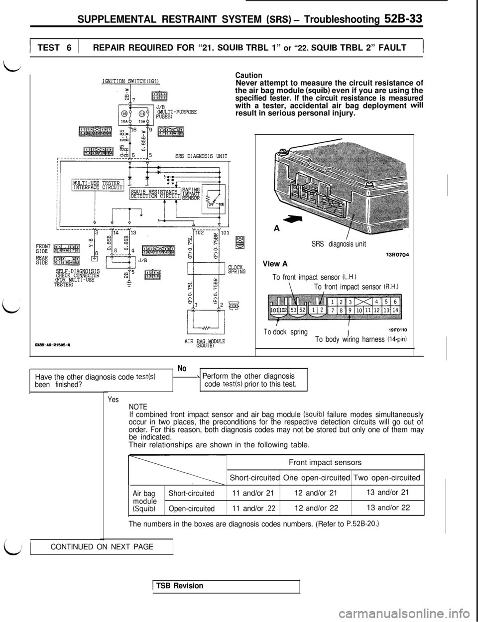
SUPPLEMENTAL RESTRAINT SYSTEM (SRS) - Troubleshooting 52B-33
1 TEST 6 )REPAIR REQUIRED FOR “21. SQUIB TRBL 1” or “22. SQUIB TRBL 2” FAULT1
i
FRONTSIDE
Ez
IGNITION SWITCH(IG1)CautionNever attempt to measure the circuit resistance of
the air bag module
(squib) even if you are using thespecified tester. If the circuit resistance is measuredwith a tester, accidental air bag deployment will
result in serious personal injury.
SRS DIAGNOSIS UNIT
------I
SELF-DIAGNOISISCHECK CONNECTOR(FOR MULTI-USETESTER)ms!+Ax-Pls95-Y
J/B
AIR (BSAgGU#DULEView A
SRS diagnosisunit
13uo704
To front impact sensor (L.H.1
\To front impact sensor (R.H.)
Todock springI19FOllOTo body wiring harness (IQpin)
No
Have the other diagnosis code test(s)/> Perform the other diagnosis
been finished?code test(s) prior to this test.
/I
Yes
NOTE
If combined front impact sensor and air bag module (squib) failure modes simultaneously
occur in two places, the preconditions for the respective detection circuits will go out of
order. For this reason, both diagnosis codes may not be stored but only one of them may
be indicated.Their relationships are shown in the following table.
Front impact sensors
Short-circuited One open-circuited Two open-circuited
Air bagShort-circuited11 and/or 2112 and/or 2113 and/or 21
module(Squib)Open-circuited11 and/or .2212 and/or 2213 and/or 22
The numbers in the boxes are diagnosis codes numbers. (Refer to P.52B-20.)
LICONTINUED ON NEXT PAGE
1 TSB Revision
Page 1087 of 1146
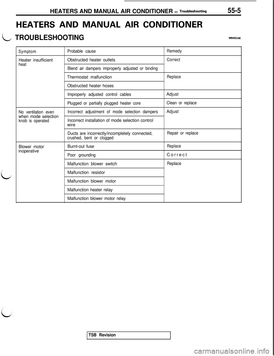
HEATERS AND MANUAL AIR CONDITIONER - Troubleshooting55-5
HEATERS AND MANUAL AIR CONDITIONER
t+-/ TROUBLESHOOTING
L
M55ECAE
Symptom
Heater insufficientheatProbable cause
Obstructed heater outlets
Blend air dampers improperly adjusted or binding
Thermostat malfunction
Obstructed heater hoses
Remedy
Correct
Replace
No ventilation evenwhen mode selectionknob is operatedImproperly adjusted control cables
Plugged or partially plugged heater core
Incorrect adjustment of mode selection dampersIncorrect installation of mode selection controlwire
Ducts are incorrectly/incompletely connected,crushed, bent or clogged
Burnt-out fuse
Poor grounding
Malfunction blower switch
Malfunction resistorAdjust
Clean or replace
Adjust
Blower motor
inoperative
Repair or replace
ReplaceCorrect
Replace
Malfunction blower motor
Malfunction heater relay
Malfunction blower motor relay
TSB Revision
Page 1091 of 1146
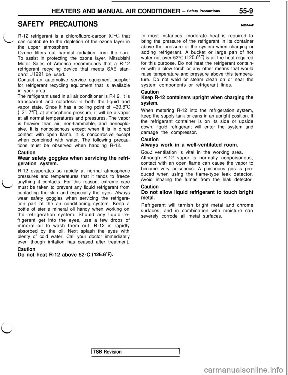
HEATERS AND MANUAL AIR CONDITIONER - safety Pre=utm55-9
SAFETY PRECAUTIONSR-12 refrigerant is a chlorofluoro-carbon
(CFC) that
can contribute to the depletion of the ozone layer in
the upper atmosphere.
Ozone filters out harmful radiation from the sun.
To assist in protecting the ozone layer, Mitsubishi
Motor Sales of America recommends that a R-12
refrigerant recycling device that meets SAE stan-
dard
J1991 be used.
Contact an automotive service equipment supplier
for refrigerant recycling equipment that is available
in your area.
The refrigerant used in all air conditioner is R-l 2. It is
transparent and colorless in both the liquid and
vapor state. Since it has a boiling point of
-29.8”C(-21.7”F), at atmospheric pressure, it will be a vapor
at all normal temperatures and pressures. The vapor
is heavier than air, non-flammable, and nonexplo-
sive. It is nonpoisonous except when it is in direct
contact with open flame. It is noncorrosive except
when combined with water. The following precau-
tions must be observed when handling R-12.
CautionWear safety goggles when servicing the refri-
geration system.R-12 evaporates so rapidly at normal atmospheric
pressures and temperatures that it tends to freeze
anything it contacts. For this reason, extreme care
must be taken to prevent any liquid refrigerant from
contacting the skin and especially the eyes. Always
wear safety goggles when servicing the refrigera-
tion part of the air conditioning system. Keep a
bottle of sterile mineral oil handy when working on
the refrigeration system. Should any liquid re-
frigerant get into the eyes, use a few drops of
mineral oil to wash them out. R-12 is rapidly
absorbed by the oil. Next splash the eyes with
plenty of cold water. Call your doctor immediately
even though irritation has ceased after treatment.
CautionDo not heat R-12 above 52°C
(125.6”F).
M55PAAFIn most instances, moderate heat is required to
bring the pressure of the refrigerant in its container
above the pressure of the system when charging or
adding refrigerant. A bucket or large pan of hot
water not over 52°C
(125.6”F) is all the heat required
for this purpose. Do not heat the refrigerant contain-
er with a blow torch or any other means that would
raise temperature and pressure above this tempera-
ture. Do not weld or steam clean on or near the
system components or refrigerant lines.
Caution
Keep R-12 containers upright when charging the
system.When metering R-12 into the refrigeration system,
keep the supply tank or cans in an upright position. If
the refrigerant container is on its side or upside
down, liquid refrigerant will enter the system and
damage the compressor.
CautionAlways work in a well-ventilated room.
Good ventilation is vital in the working area.
Although R-12 vapor is normally nonpoisonous,
contact with an open flame can cause the vapor to
become very poisonous. A poisonous gas is pro-
duced when using the flame-type leak detector.
Avoid inhaling the fumes from the leak detector.
CautionDo not allow liquid refrigerant to touch bright
metal.Refrigerant will tarnish bright metal and chrome
surfaces, and in combination with moisture can
severely corrode all metal surfaces.
1 TSB Revision