alternator MITSUBISHI 3000GT 1991 User Guide
[x] Cancel search | Manufacturer: MITSUBISHI, Model Year: 1991, Model line: 3000GT, Model: MITSUBISHI 3000GT 1991Pages: 1146, PDF Size: 76.68 MB
Page 1098 of 1146

55-16 HEATERS AND MANUAL AIR CONDITIONER -Service Adjustment Procedures
LOW CHARGE~
If the system has not lost all of its refrigerant charge; locate and
repair all leaks. If it is necessary to increase the system
pressure to find the leak (because of an especially low charge)
‘iaadd of refrigerant. If it is oossible to reoair the leak without
discharging-the refrigerant system, use the procedure for
correcting low refrigerant level.
HANDLING TUBING AND FITTINGSM55FlAFKinks in the refrigerant tubing or sharp bends in the refrigerant
hose lines will greatly reduce the capacity of the entire system.
High pressures are produced in the system when it is
operating. Extreme care must be exercised to make sure that
all connections are pressure tight. Dirt and moisture can enter
the system when it is opened for repair or replacement of lines
or components. The following precautions must be observed.
The system must be completely discharged before opening
any fitting of connection in the refrigeration system. Open
fittings with caution even after the system has been dis-
charged. If any pressure is noticed as a fitting is loosened, allow
trapped pressure to bleed off very slowly.
Never attempt to rebend formed lines to fit. Use the correct
line for the installation you are servicing.
A good rule for the flexible hose lines is keep the radius of all
bends at least 10 times the diameter of the hose.
Sharper bends will reduce the flow of refrigerant. The flexible
hose lines should be routed so that they are at least 80 mm (3
in.) from the exhaust manifold. It is good practice to inspect all
flexible hose lines at least once a year to make sure they are in
good condition and properly routed.
\ Aj iUnified plumbing connections with O-rings. These O-rings are
-not reusable.
I
COMPRESSOR NOISEM55FlAD
When investigating an air conditioning related noise, you must
first know the conditions when the noise occurs. These
conditions are: weather, vehicle speed, in gear on neutral,
engine temperature or any other special conditions.
Noises that develop during air conditioning operation can often
be misleading. For example: what sounds like a failed front
bearing or connecting rod. may be caused by loose bolts, nuts,
mounting brackets, or a loose clutch assembly. Verify acces-
sory drive belt tension (power steering or alternator).
Improper accessory drive belt tension can cause a misleading
noise when the compressor is engaged and little or no noise
when the compressor is disengaged.
Drive belts are speed sensitive. That is, at different engine
speeds, and depending upon belt tension, belts can develop
unusual noises that are often mistaken for mechanical prob-
lems within the compressor.
TSB Revision
Page 1109 of 1146

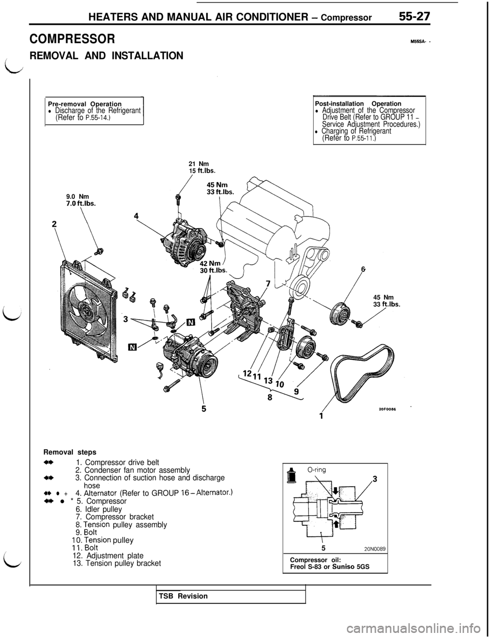
HEATERS AND MANUAL AIR CONDITIONER - Compressor55-27
COMPRESSOR
M55SA- -
/REMOVAL AND INSTALLATION
iJ
iPre-removal Operation
l Discharge of the Refrigerant(Refer to P.55-14.)9.0 Nm
7.Oft.lbs.
\Post-installation Operation
l Adjustment of the Compressor
Drive Belt (Refer to GROUP 11 -Service Adjustment Procedures.)l Charging of Refrigerant(Refer to P.55-11.)21 Nm
15 ftlbs.Removal steps
a*1. Compressor drive belt
2. Condenser fan motor assembly
4*3. Connection of suction hose and discharge
41) l +4. !%znator (Refer to GROUP l6-Alternator.)*I) l * 5. Compressor
6. Idler pulley
7. Compressor bracket
!I zorr-rion pulley assembly;
;: Fontsion pulley
12. Adjustment plate
13. Tension pulley bracket6
45 Nm
33 ft.lbs.
52ONOO89Compressor oil:
Freol S-83 or Suniso 5GS
TSB Revision
Page 1115 of 1146

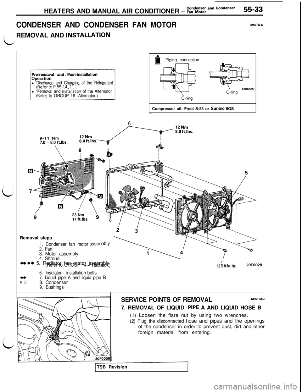
HEATERS AND MANUAL AIR CONDITIONER - ::“dE:; and Condenser55-33
CONDENSER AND CONDENSER FAN MOTOR
MFSTA-A
idREMOVAL AND
IlilSTALLATlONPre-removal and Post-installation
l Discharge and Charging of the Refrigerant
l Removal and lnsiallation of the Alternator(Refey to GROUP 16 -Alternator.)
6
f: Piplng connection
@
20N00890-ring
d-ringCompressor oil: Freol S-83 or Suniso 5GS
9-11 Nm
7.0 - 8.0 ftlbs.
9’23’Nm17 ft.lbs.
asset-rRemoval steps1. Condenser fan motor
2. Fan
3. Motor assembly
4. Shroud
w w 5. Radiator fan motor assembly(Refer to GROUP 14- Radiator.)
Insulator installationbolts
6.4*7. Liquid pipe A and liquid pipe Bl *8. Condenser9.Bushings
/9.0 7.0ft.lbs. Nm2OFOO28
SERVICE POINTS OF REMOVALM!XTEtAC7. REMOVAL OF LIQUID
‘PIPE A AND LIQUID HOSE B
(1) Loosen the flare nut by using two wrenches.
(2) Plug the disconnected hose and pipes and the openingsof the condenser in order to prevent dust, dirt and other
foreign material from entering.
TSB Revision