ESP inoperative MITSUBISHI 3000GT 1991 Service Manual
[x] Cancel search | Manufacturer: MITSUBISHI, Model Year: 1991, Model line: 3000GT, Model: MITSUBISHI 3000GT 1991Pages: 1146, PDF Size: 76.68 MB
Page 4 of 1146
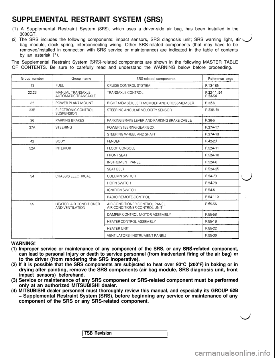
SUPPLEMENTAL RESTRAINT SYSTEM (SRS)
dir J
bag module, clock spring, interconnecting wiring. Other SRS-related comp\
onents (that may have to be
(*).
The Supplemental Restraint System (SRSI-related components are shown in the following MASTER TABLE
OF CONTENTS. Be sure to carefully read and understand the WARNING below \
before proceeding.
Group number
22.23
32
36
42
52A
Group nameSRS-related components
FUELCRUISE CONTROL SYSTEM/ P.13-185
MANUALTRANSAXLE.TRANSAXLE CONTROLAUTOMATIC TRANSAXLE
POWER PLANT MOUNTRIGHT MEMBER, LEFT MEMBER AND CROSSMEMBERP.32-6
ELECTRONIC CONTROLSUSPENSION’STEERING ANGULAR VELOCITY SENSORP.33B-19
PARKING BRAKESPARKING BRAKE LEVER AND PARKiNG BRAKE CABLE/ P.36~5I
STEERING/POWER STEERING GEAR BOX/ P.37A-17
/STEERING WHEEL AND SHAFTj P.37A-13
BODY
INTERIOR
FENDER
FLOOR CONSOLE/ P.52A-11
FRONT SEAT
INSTRUMENT PANEL
P52A-18
P.52A-8
CHASSIS ELECTRICAL
SEAT BELT
COLUMN SWITCH
HORN SWITCH
IGNITION SWITCH
P.52A-25
P.54-73
P.54-78
1 P.54-6
RADIO REMOTE-CONTROL/ P.54.110
HEATER, AIR CONDITIONERAIR-CONDITIONER CONTROL PANELAND VENTILATIONAIR-CONDITIONER CONTROL UNITP.55-56
/DAMPER CONTROL MOTOR ASSEMBLYI
/HEATER CONTROL ASSEMBLY1 P.55-18I
HEATER UNIT.1 P.55-22
WARNING!
VENTILATORS (INSTRUMENT PANEL)P.55-36
(1) Improper service or maintenance of any component of the SRS, or an\
y SRSrelated component,
can lead to personal injury or death to service personnel (from inadver\
tent firing of the air bag) or
to the driver (from rendering the SRS inoperative).
(260°F) in baking or in
drying after painting, remove the SRS components (air bag module, SRS d\
iagnosis unit, front
perfarmed
only at an authorized MITSUBISHI dealer.
52B
- Supplemental Restraint System (SRS), before beginning any service or m\
aintenance of any
component of the SRS or any SRS-related component.
1 TSB RevisionI
Page 107 of 1146
FUEL
SYSTEM
CONTENTSM13AA- _
CRUISE CONTROL SYSTEM. . . . . . . . . . . . . . . . . . . . . . . . . . . .158SPECIFICATIONS. . . . . . . .._._....................................................155
CRUISE CONTROL SYSTEM*................................................185
SERVICE ADJUSTMENT PROCEDURES............................178
Cruise Control Cables Inspection and Adjustment........178Cruise Control SystemInspection....................................179individual Parts Inspection....................................................181
SPECIAL TOOLS........................................................................159
SPECIFICATIONS....................................................................158
General Specifications........................................................158Service Specifications........................................................158
TROUBLESHOOTING............................................................159
Check Chart............................................................................163Harness and Components Layout....................................176Preliminary Inspection........................................................159Self-diagnosis Checking........................................................172Troubleshooting Quick Reference Chart............................159
ENGINE CONTROL............................................155
ENGINE CONTROL................................................................157
SERVICE ADJUSTMENT PROCEDURES............................156
Accelerator Cable Inspection and Adjustment................156Accelerator Switch Inspection and Adjustment................156
Service Specifications........................................................
155
TROUBLESHOOTING............................................................
155
Accelerator Cable and Accelerator Pedal........................155
FUEL SYSTEM....................................................3
DETONATION SENSOR........................................................154
FUEL FILTER............................................................................
153
FUEL LINE AND VAPOR LINE................................................151
FUEL PUMP AND FUEL GAUGE UNIT ASSEMBLYAND OVERFILL LIMITER (TWO-WAY VALVE)................149
FUEL TANK.................................................................................146
GENERAL INFORMATION
....................................................
3
MPI System Diagram............................................................3
INJECTOR................................................................................141
ON-VEHICLE INSPECTION OF MPI COMPONENTS........36
Active Exhaust Control Unit
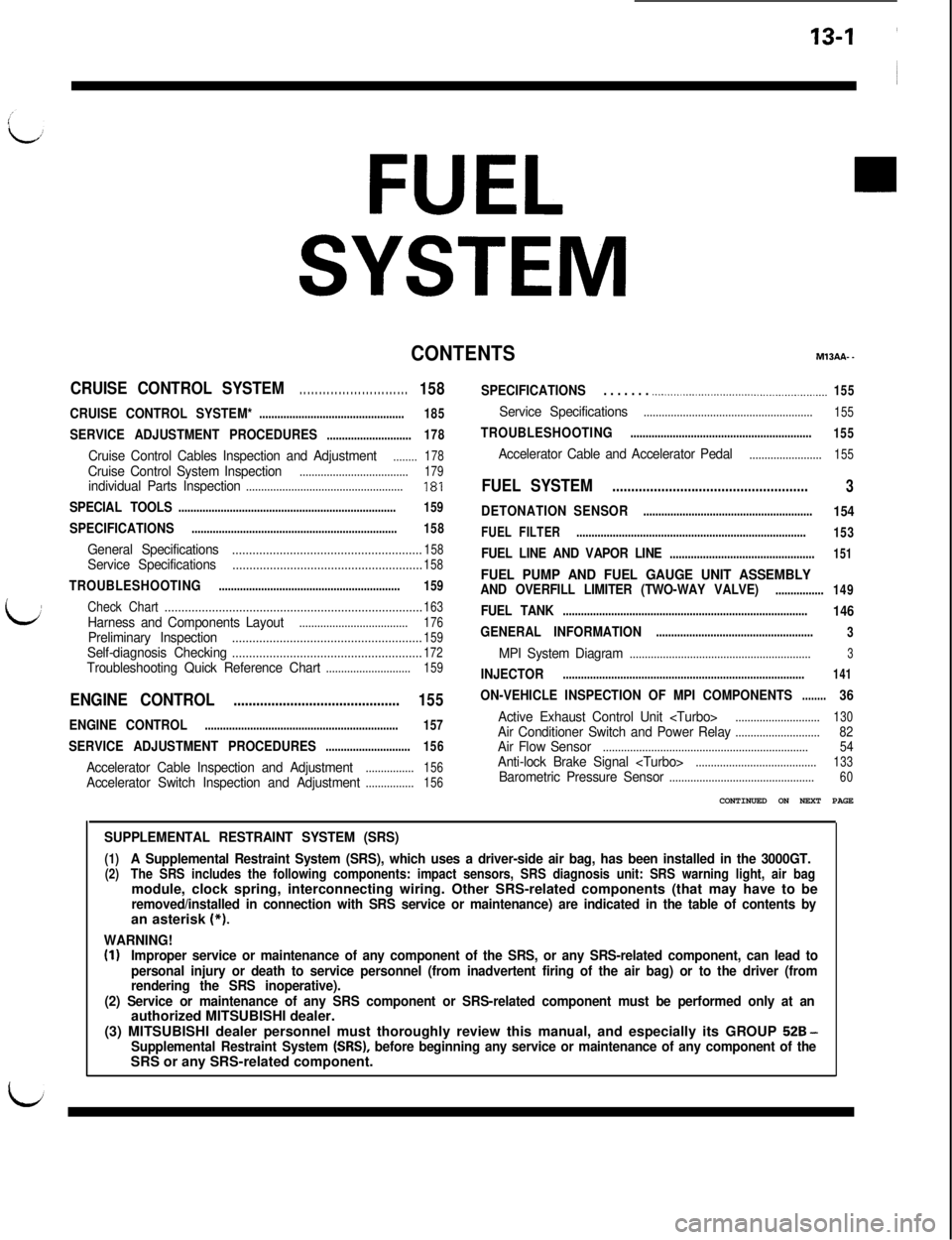
SUPPLEMENTAL RESTRAINT SYSTEM (SRS)
(1)A Supplemental Restraint System (SRS), which uses a driver-side air bag, has been installed in the 3000GT.(2)The SRS includes the following components: impact sensors, SRS diagnosis unit: SRS warning light, air bagmodule, clock spring, interconnecting wiring. Other SRS-related components (that may have to be
removed/installed in connection with SRS service or maintenance) are indicated in the table of contents byan asterisk (*).
WARNING!(I)Improper service or maintenance of any component of the SRS, or any SRS-related component, can lead to
personal injury or death to service personnel (from inadvertent firing of the air bag) or to the driver (from
rendering the SRS inoperative).
(2) Service or maintenance of any SRS component or SRS-related component must be performed only at anauthorized MITSUBISHI dealer.
(3) MITSUBISHI dealer personnel must thoroughly review this manual, and especially its GROUP
528 -Supplemental Restraint System (SRS), before beginning any service or maintenance of any component of theSRS or any SRS-related component.
Page 381 of 1146
22-1
iv,MANUAL ~
TRANSAXLE
~
I
CONTENTSM22AA. -
MANUAL TRANSAXLE
GENERAL INFORMATION....................................................48
SERVICE ADJUSTMENT PROCEDURES
............................51
Drive Shaft OilSealsReplacement....................................
52Speedometer Cable Replacement....................................
53Transfer Oil Seal Replacement............................................53Transmission Oil Level Inspection....................................51Transmission Oil Replacement............................................51
SHIFT LEVER ASSEMBLY....................................................
53
SPECIAL TOOLS........................................................................50
SPECIFICATIONS
....................................................................49
General Specifications........................................................49Lubricants............................................................................49
TRANSAXLE ASSEMBLY....................................................56,60
TRANSAXLE CONTROL*........................................................54
TRANSFER ASSEMBLY
........................................................59
MANUAL TRANSAXLE
CLUTCH HOUSING ASSEMBLY............................................46
DIFFERENTIAL ASSEMBLY
....................................................43
5TH SPEED SYNCHRONIZER ASSEMBLY
........................28
GENERAL INFORMATION
....................................................2INTERMEDIATE GEAR ASSEMBLY
....................................
OUTPUT SHAFT ASSEMBLY................................................
SERVICE ADJUSTMENT PROCEDURES............................
Drive Shaft Oil Seals Replacement....................................Speedometer CableReplacement....................................Transmission Oil Level Inspection....................................Transmisston Oil Replacement............................................
SHIFT LEVER ASSEMBLY....................................................
SHIFT RAILS AND FORKS....................................................
SPECIAL TOOLS........................................................................
SPECIFICATIONS....................................................................
General Specifications........................................................
Lubricants............................................................................
Sealants and Adhesives........................................................Service Specifications........................................................
Snap Ring (for Adjustment) and Spacer............................
SPEEDOMETER DRIVEN GEAR ASSEMBLY....................
TRANSAXLE ASSEMBLY _____...._........__....................................
TRANSAXLE CONTROL*. . ..________.___.._ ..__._.__.__...............
36
41
9
10
9
9
9
13
42
6
3z
63
3
45
14
11TROUBLESHOOTING
___.._______._____.......,..................................8
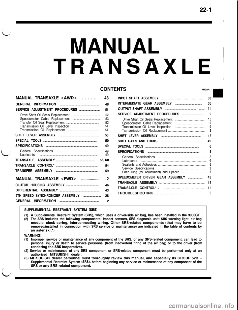
SUPPLEMENTAL RESTRAINT SYSTEM (SRS)
(1)A Supplemental Restraint System (SRS), which uses a driver-side air bag, has been installed in the 3000GT.(2)The SRS includes the following components: impact sensors, SRS diagnosis unit: SRS warning light, air bagmodule, clock spring, interconnecting wiring. Other SRS-related components (that may have to be
removed/installed in connection with SRS service or maintenance) are indicated in the table of contents byan asterisk (*).
WARNING!(1)Improper service or maintenance of any component of the SRS, or any SRS-related component, can lead to
personal injury or death to service personnel (from inadvertent firing of the air bag) or to the driver (fromrendering the
SRS inoperative).(2) Service or maintenance of any SRS component or SRS-related component must be performed only at an
authorized MITSUBISHI dealer.(3) MITSUBISHI dealer personnel must thoroughly review this manual, and especially its GROUP 52B
-Supplemental Restraint System (SRS), before beginning any service or maintenance of any component of theSRS or any SRS-related component.
Page 443 of 1146
23-1
AUTOMATIC
TRANSAXLE
CONTENTSMZJAA- _
ANNULUS GEAR AND TRANSFER DRIVE GEARTransmission Fluid Level Inspection................................46SET................................................................................................
102Transmission Fluid Replacement........................................
46
DIFFERENTIAL........................................................................104SPECIAL TOOLS........................................................................
16
:......................................... 12IEND CLUTCH ASSEMBLY....................................................99SPECIFICATIONS..........................
FRONT CLUTCH ASSEMBLY................................................95
GENERAL INFORMATlON....................................................2
KICKDOWN SERVO................................................................
107
LOW-REVERSE BRAKE............................................................
107
OIL PUMP....................................................................................93
PLANETARY GEAR................................................................
100
REAR CLUTCH ASSEMBLY....................................................97
SELECTOR LEVER ASSEMBLY............................................58
SERVICE ADJUSTMENT PROCEDURES............................46
Accelerator Switch
Inspection and Adjustment................
50Drive Shaft Oil Seals Replacement....................................
52Inhibitor Switch and Control Cable Adjustment................
52Key Interlock Mechanism Check........................................50KickdownServo Adjustment................................................
47Line Pressure Adjustment....................................................
48Reducing Pressure Adjustment........................................
49Selector Lever Operation Check........................................
50Shift Lock Mechanism Check............................................51Speedometer Cable Replacement....................................53
General Specifications........................................................12Lubricants............................................................................15Service Specifications........................................................12Spacer and Snap Ring........................................................13Valve Body Spring Identification Chart............................13
SPEEDOMETER DRIVEN GEAR ASSEMBLY....................106
TRANSAXLE ASSEMBLY........................................................62
TRANSAXLE CONTROL*........................................................54
TRANSAXLE OIL COOLER, HOSES, TUBES
....................66
TRANSFER SHAFT....................................................................92
TROUBLESHOOTING............................................................
19
A/T Safety-lock System Troubleshooting........................44Converter Stall Test............................................................
43
Diagnosis and Test
................................................................
22
Element in Use at Each Position of Selector Lever........31Inspection
of ControlSystem............................................
28Inspection of Electronic Control System Components....32Oil Pressure Tests................................................................
39ShiftPatterns....................................................................
31,42Troubleshooting Guide........................................................
20
VALVE BODY. . . .._._.................................................................... 108
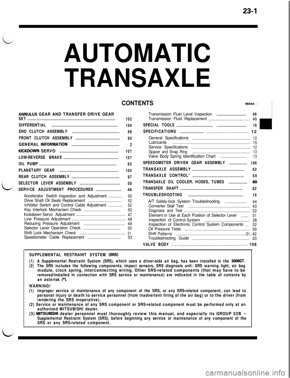
SUPPLEMENTAL RESTRAINT SYSTEM (SRS)
(1)A Supplemental Restraint System (SRS), which uses a driver-side air bag, has been installed in the 3668GT.(2)The SRS includes the following components: impact sensors, SRS diagnosis unit: SRS warning light, air bagmodule, clock spring, interconnecting wiring. Other SRS-related components (that may have to beremoved/installed in connection with SRS service or maintenance) are indicated in the table of contents byan asterisk (*).
WARNING!(1)Improper service or maintenance of any component of the SRS, or any SRS-related component, can lead topersonal injury or death to service personnel (from inadvertent firing of the air bag) or to the driver (from
rendering the SRS inoperative).
(2) Service or maintenance of any SRS component or SRS-related component must be performed only at an
authorized MITSUBISHI dealer.
(3) MlTSUBISHI dealer personnel must thoroughly review this manual, and especially its GROUP 52B -Supplemental Restraint System (SRS), before beginning any service or maintenance of any component of the
ISRS or any SRS-related component.
Page 643 of 1146
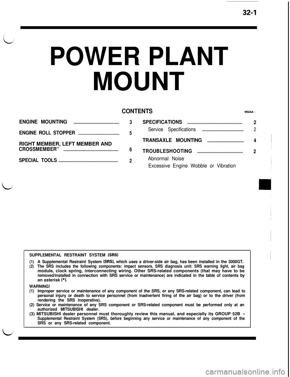
32-1
POWER PLANTMOUNT
CONTENTSMZAA- _
ENGINE MOUNTING........................................
3SPECIFICATIONS................................................2
ENGINE ROLL STOPPER
5Service Specifications....................................2....................................
TRANSAXLE MOUNTING................................4RIGHT MEMBER, LEFT MEMBER AND
CROSSMEMBER”................................................6TROUBLESHOOTING........................................2
SPECIAL TOOLSAbnormal Noise....................................................
2
Excessive Engine Wobble or Vibration
SUPPLEMENTAL RESTRAINT SYSTEM (SRS)
(1)A Supplemental Restraint System (SRS), which uses a driver-side air bag, has been installed in the 3000GT.(2)The SRS includes the following components: impact sensors, SRS diagnosis unit: SRS warning light, air bagmodule, clock spring, interconnecting wiring. Other SRS-related components (that may have to be
removed/installed in connection with SRS service or maintenance) are indicated in the table of contents byan asterisk (*).
WARNING!(1)Improper service or maintenance of any component of the SRS, or any SRS-related component, can lead to
personal injury or death to service personnel (from inadvertent firing of the air bag) or to the driver (from
rendering the SRS inoperative).
(2) Service or maintenance of any SRS component or SRS-related component must be performed only at an
authorized MITSUBISHI dealer.(3) MITSUBISHI dealer personnel must thoroughly review this manual, and especially its GROUP 52B
-Supplemental Restraint System (SRS), before beginning any service or maintenance of any component of theSRS or any SRS-related component.
Page 663 of 1146
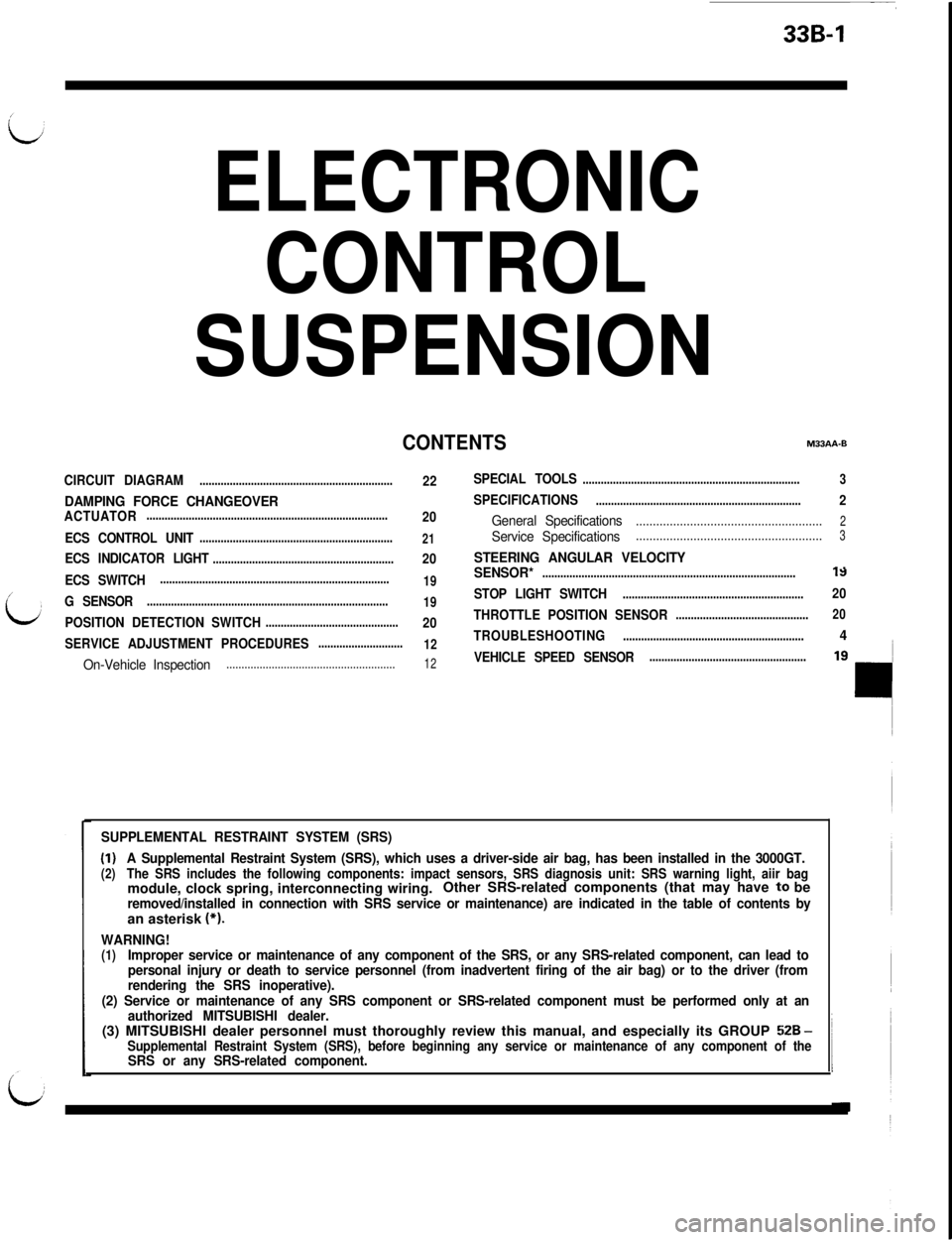
33B-1
ELECTRONIC
CONTROL
SUSPENSION
CONTENTSM33AA-B
CIRCUIT DIAGRAM
22SPECIAL TOOLS........................................................................3
................................................................
DAMPING FORCE CHANGEOVERSPECIFICATIONS....................................................................2
ACTUATOR................................................................................20General Specifications.......................................................2
ECS CONTROL UNIT................................................................21Service Specifications.......................................................3
ECS INDICATOR LIGHT............................................................20STEERING ANGULAR VELOCITYa .
ECS SWITCH............................................................................
19
G SENSOR................................................................................
19
POSITION DETECTION SWITCH............................................20
SERVICE ADJUSTMENT PROCEDURES
............................
12
On-Vehicle Inspection........................................................12
SENSOR*....................................................................................-IY
STOP LIGHT SWITCH............................................................20
THROTTLE POSITION SENSOR
............................................20
TROUBLESHOOTING............................................................4
VEHICLE SPEED SENSOR....................................................
SUPPLEMENTAL RESTRAINT SYSTEM (SRS)
(I)A Supplemental Restraint System (SRS), which uses a driver-side air bag, has been installed in the 3000GT.(2)The SRS includes the following components: impact sensors, SRS diagnosis unit: SRS warning light, aiir bagmodule, clock spring, interconnecting wiring.Other SRS-related components (that may have 1:o be
removed/installed in connection with SRS service or maintenance) are indicated in the table of contents byan asterisk (*).
WARNING!(1)Improper service or maintenance of any component of the SRS, or any SRS-related component, can lead to
personal injury or death to service personnel (from inadvertent firing of the air bag) or to the driver (from
rendering the SRS inoperative).
(2) Service or maintenance of any SRS component or SRS-related component must be performed only at an
authorized MITSUBISHI dealer.(3) MITSUBISHI dealer personnel must thoroughly review this manual, and especially its GROUP
Ei2B -Supplemental Restraint System (SRS), before beginning any service or maintenance of any component of theSRS or any SRS-related component.
Page 723 of 1146
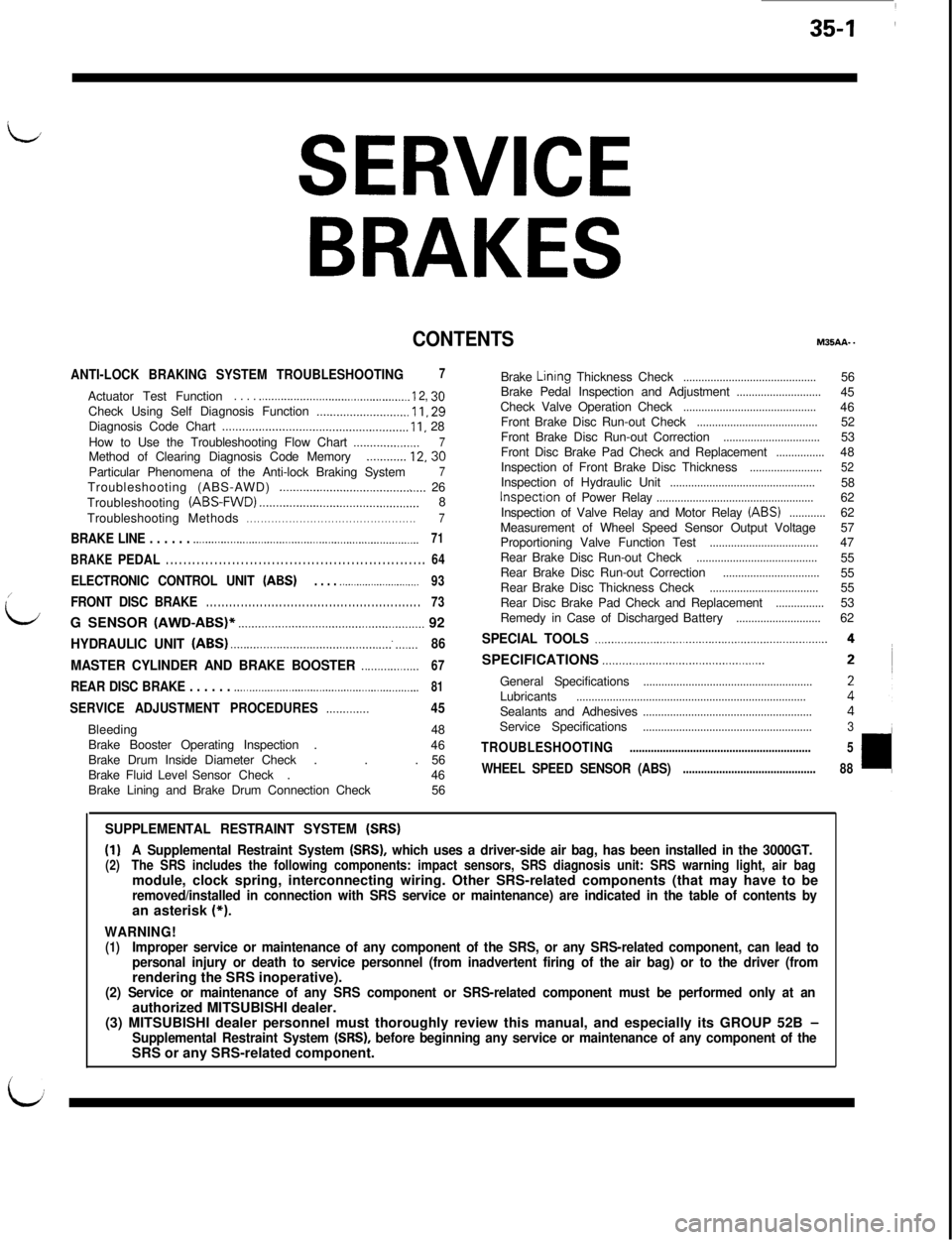
L,
SERVICE
BRAKES
CONTENTSM35AA..
ANTI-LOCK BRAKING SYSTEM TROUBLESHOOTING7Actuator Test Function
. . . . ..___..._____.__................................ I 2, 36Check Using Self Diagnosis Function __._.....,_._.._____........ 11, 28
Diagnosis Code Chart ..,,........,......_..................................,. 1 I, 28
How to Use the Troubleshooting Flow Chart
_____.___......._._.7Method of Clearing Diagnosis Code Memory._.,._...... 12, 30
Particular Phenomena of the Anti-lock Braking System
7Troubleshooting (ABS-AWD) ._______._.._...........................,... 26
Troubleshooting (ABS-FWD) ______.._._........_...........,.....,.....,....8
TroubleshootingMethods. . . . . . . . . . . . . . . . . . . . . . . . . . . . . . . . . . . . . . . . . . . . . . . .7
BRAKE LINE . . . . . . .._.......................................................................71
BRAKEPEDAL. . . . . . . . . . . . . . . . . . . . . . . . . . . . . . . . . . . . . . . . . . . . . . . . . . . . . . . . . . .64
ELECTRONIC CONTROL UNIT (ABS). . . . .._._..___..__._............93/
L
FRONT DISC BRAKE. . . . . . . . . . . . . . . . . . . . . . . . . . . . . . . . . . . . . . . . . . . . . . . . . . . . . . . .73G SENSOR (AWD-ABS)’
____.____.___.__._._.................,,......,.....,.... 92
HYDRAULIC UNIT (ABS) .___.._._._._.______.............,...,,..........~ .,_____86
MASTER CYLINDER AND BRAKE BOOSTER ..__.._____.._____67SPECIFICATIONS ._....._.___.....................................
REAR DISC BRAKE . . . . . . .._..._._.___................................................81
SERVICE ADJUSTMENT PROCEDURES..___........45Bleeding48
Brake Booster Operating Inspection.
46
Brake Drum Inside Diameter Check. . .56
BrakeFluidLevelSensor Check.46
Brake Lining and Brake Drum Connection Check56Brake
Linrng Thickness Check............................................Brake Pedal Inspection and Adjustment............................Check Valve Operation Check............................................Front Brake Disc Run-out Check........................................Front Brake Disc Run-out Correction................................Front Disc Brake Pad Check and Replacement................Inspection of Front Brake Disc Thickness........................Inspection of Hydraulic Unit................................................Inspectton of Power Relay....................................................Inspection of Valve Relay and Motor Relay (ABS)............Measurement of Wheel Speed Sensor Output Voltage
Proportioning Valve Function Test
....................................Rear Brake Disc Run-out Check........................................Rear Brake Disc Run-out Correction................................Rear Brake Disc Thickness Check....................................Rear Disc Brake Pad Check and Replacement................Remedy in Case of DischargedBattery............................56
45
46
52
53
48
5258
62
62
57
47
55
55
55
53
62
SPECIAL TOOLS ..__.......___..........................................................General Specifications
........................................................Lubricants............................................................................Sealants and Adhesives........................................................Service Specifications........................................................3
TROUBLESHOOTING............................................................5
WHEEL SPEED SENSOR (ABS)............................................88
SUPPLEMENTAL RESTRAINT SYSTEM (SRS)
(1)A Supplemental Restraint System (SRS), which uses a driver-side air bag, has been installed in the 3000GT.(2)The SRS includes the following components: impact sensors, SRS diagnosis unit: SRS warning light, air bagmodule, clock spring, interconnecting wiring. Other SRS-related components (that may have to be
removed/installed in connection with SRS service or maintenance) are indicated in the table of contents byan asterisk (*).
WARNING!(1)Improper service or maintenance of any component of the SRS, or any SRS-related component, can lead to
personal injury or death to service personnel (from inadvertent firing of the air bag) or to the driver (fromrendering the SRS inoperative).
(2) Service or maintenance of any SRS component or SRS-related component must be performed only at anauthorized MITSUBISHI dealer.
(3) MITSUBISHI dealer personnel must thoroughly review this manual, and especially its GROUP 52B
-Supplemental Restraint System (SRS), before beginning any service or maintenance of any component of theSRS or any SRS-related component.
i
Page 817 of 1146
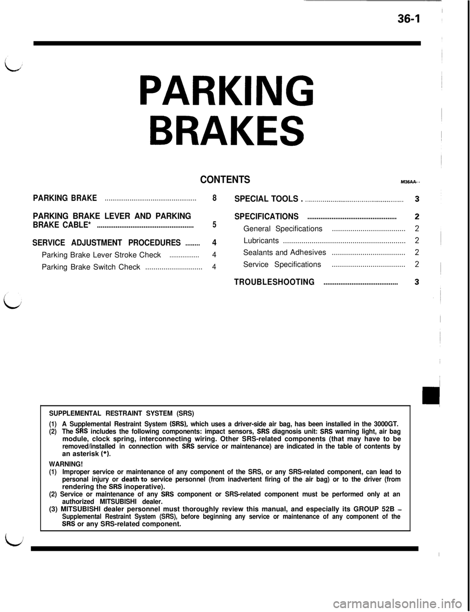
36-1
PARKING
BRAKES
CONTENTSM36AA-.
PARKINGBRAKE. . . . . . . . . . . . . . . . . . . . . . . . . . . . . . . . . . . . . . . . . . . . . . . .8SPECIAL TOOLS . .._.._.............................................
PARKING BRAKE LEVER AND PARKINGSPECIFICATIONS................................................
BRAKE CABLE*....................................................5General Specifications....................................
SERVICE ADJUSTMENT PROCEDURES4Lubricants....................................................................Parking Brake Lever Stroke Check4Sealants
andAdhesives....................................................Parking Brake Switch Check
............................4Service Specifications....................................
TROUBLESHOOTING........................................
i
SUPPLEMENTAL RESTRAINT SYSTEM (SRS)
(1)A Supplemental Restraint System (SRS), which uses a driver-side air bag, has been installed in the 3000GT.(2)The SRS includes the following components: impact sensors, SRS diagnosis unit: SRS warning light, air bagmodule, clock spring, interconnecting wiring. Other SRS-related components (that may have to be
removed/installed in connection with SRS service or maintenance) are indicated in the table of contents byan asterisk (*).
WARNING!(1)Improper service or maintenance of any component of the SRS, or any SRS-related component, can lead to
personal injury or death to service personnel (from inadvertent firing of the air bag) or to the driver (fromrendering the SRS inoperative).(2) Service or maintenance of any SRS component or SRS-related component must be performed only at an
authorized MITSUBISHI dealer.(3) MITSUBISHI dealer personnel must thoroughly review this manual, and especially its GROUP 52B
-Supplemental Restraint System (SRS), before beginning any service or maintenance of any component of theSRS or any SRS-related component.
u
I
Page 829 of 1146
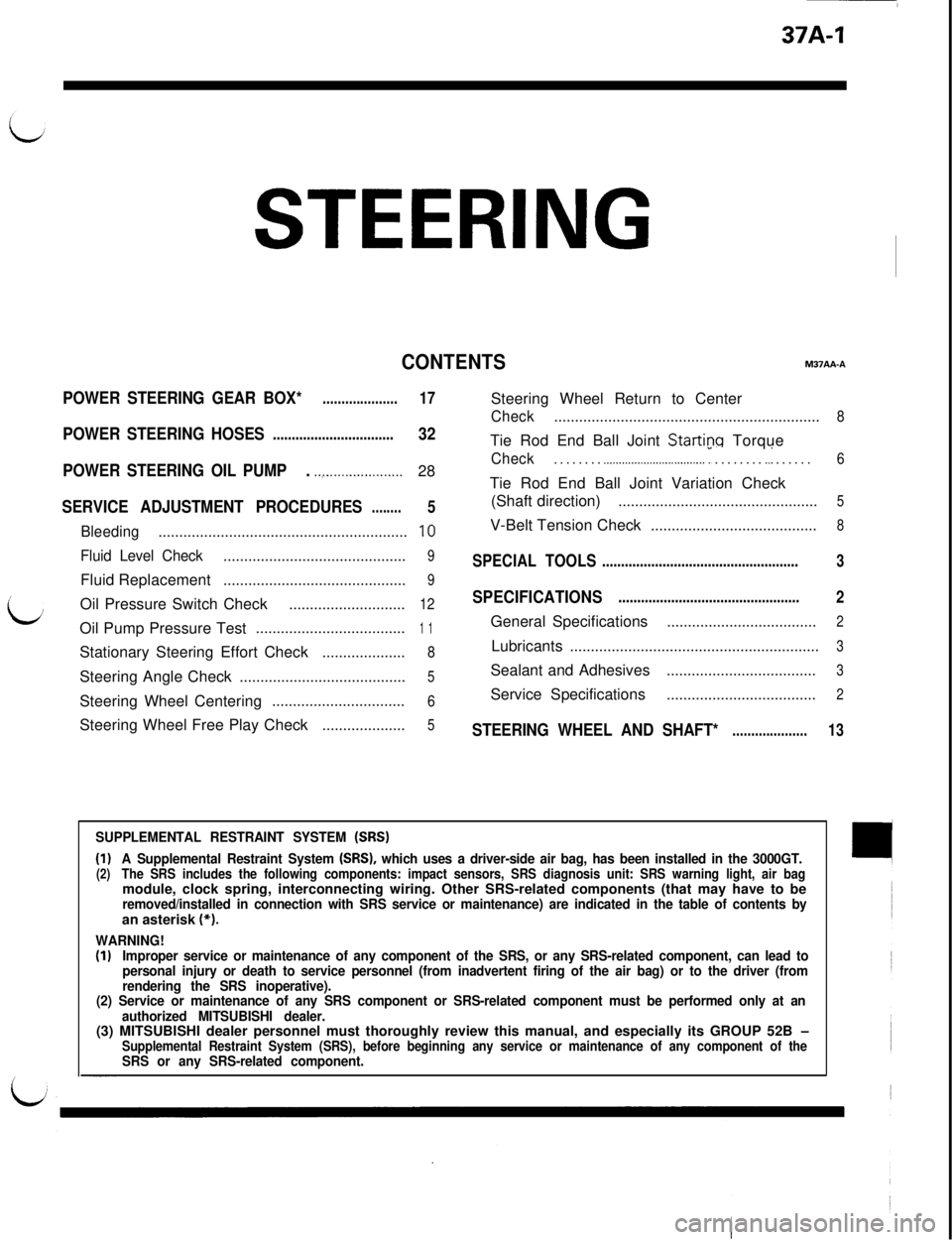
37A-1
STEERING
CONTENTSM37AA-A
POWER STEERING GEAR BOX*....................17Steering Wheel Return to Center
Check................................................................8
POWER STEERING HOSES................................32Tie Rod End Ball Joint Startinq Torque
POWER STEERING OIL PUMP. .._....................28Check. . . . . . . . .._.............................. r . . . . . . . . ..I . . . . . .6Tie Rod End Ball Joint Variation Check
SERVICE ADJUSTMENT PROCEDURES5(Shaft direction)................................................5........
Bleeding............................................................10V-Belt Tension Check........................................8
Fluid Level Check............................................9SPECIAL TOOLS....................................................3Fluid Replacement
............................................9
/
bOil Pressure Switch Check
SPECIFICATIONS2............................12................................................Oil Pump Pressure Test
....................................1 1General Specifications....................................2Stationary Steering Effort Check
....................8Lubricants............................................................3Steering Angle Check
5Sealant and Adhesives....................................3........................................Steering Wheel Centering
6Service Specifications....................................2................................Steering Wheel Free Play Check
....................5STEERING WHEEL AND SHAFT*....................13
SUPPLEMENTAL RESTRAINT SYSTEM (SRS)
(1)A Supplemental Restraint System (SRS), which uses a driver-side air bag, has been installed in the 3000GT.(2)The SRS includes the following components: impact sensors, SRS diagnosis unit: SRS warning light, air bagmodule, clock spring, interconnecting wiring. Other SRS-related components (that may have to be
removed/installed in connection with SRS service or maintenance) are indicated in the table of contents byan asterisk (*).
WARNING!(I)Improper service or maintenance of any component of the SRS, or any SRS-related component, can lead to
personal injury or death to service personnel (from inadvertent firing of the air bag) or to the driver (from
rendering the SRS inoperative).
(2) Service or maintenance of any SRS component or SRS-related component must be performed only at an
authorized MITSUBISHI dealer.(3) MITSUBISHI dealer personnel must thoroughly review this manual, and especially its GROUP 52B
-Supplemental Restraint System (SRS), before beginning any service or maintenance of any component of theSRS or any SRS-related component.
Page 873 of 1146
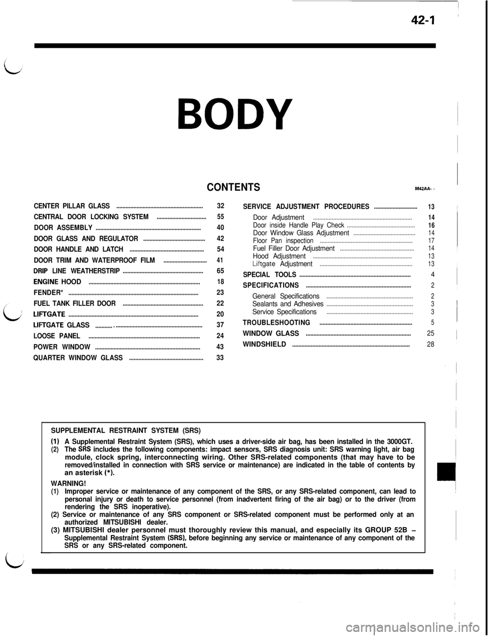
42-1
BODY
CONTENTSM42AA- -
CENTER PILLAR GLASS........................................................32
CENTRAL DOOR LOCKING SYSTEM
................................55
DOOR ASSEMBLY....................................................................40
DOOR GLASS AND REGULATOR
........................................42
DOOR HANDLE AND LATCH
................................................54
DOOR TRIM AND WATERPROOF FILM
............................41
DRIP LINE WEATHERSTRIP....................................................65
ENGINE HOOD........................................................................18
FENDER*....................................................................................23
FUEL TANK FILLER DOOR
....................................................22
LIFTGATE....................................................................................20
LIFTGATE GLASS....................................................................37
LOOSE PANEL
........................................................................24
POWER WINDOW
....................................................................43
QUARTER WINDOW GLASS
................................................33SERVICE ADJUSTMENT PROCEDURES
............................
Door Adjustment................................................................Door inside Handle Play Check............................................Door Window Glass Adjustment........................................Floor Pan inspection............................................................Fuel Filler Door Adjustment................................................Hood Adjustment................................................................Liftgate Adjustment............................................................
SPECIAL TOOLS........................................................................
SPECIFICATIONS....................................................................
General Specifications........................................................Sealants and Adhesives........................................................
ServiceSpecifications........................................................
TROUBLESHOOTING............................................................
WINDOW GLASS....................................................................
WINDSHIELD............................................................................
13
14
16
14
17
14
13
13
4
2
2
3
3
5
25
28
SUPPLEMENTAL RESTRAINT SYSTEM (SRS)
(1)A Supplemental Restraint System (SRS), which uses a driver-side air bag, has been installed in the 3000GT.(2)The SRS includes the following components: impact sensors, SRS diagnosis unit: SRS warning light, air bagmodule, clock spring, interconnecting wiring. Other SRS-related components (that may have to be
removed/installed in connection with SRS service or maintenance) are indicated in the table of contents byan asterisk (*).
WARNING!(1)Improper service or maintenance of any component of the SRS, or any SRS-related component, can lead to
personal injury or death to service personnel (from inadvertent firing of the air bag) or to the driver (from
rendering the SRS inoperative).
(2) Service or maintenance of any SRS component or SRS-related component must be performed only at an
authorized MITSUBISHI dealer.(3) MITSUBISHI dealer personnel must thoroughly review this manual, and especially its GROUP 52B
-Supplemental Restraint System (SRS), before beginning any service or maintenance of any component of the
SRS or any SRS-related component.