sensor MITSUBISHI 3000GT 1991 Service Manual
[x] Cancel search | Manufacturer: MITSUBISHI, Model Year: 1991, Model line: 3000GT, Model: MITSUBISHI 3000GT 1991Pages: 1146, PDF Size: 76.68 MB
Page 4 of 1146
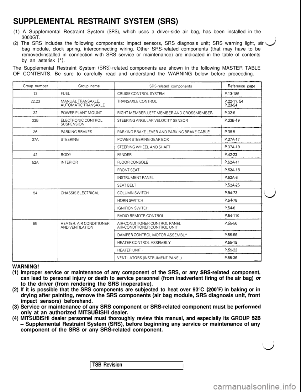
SUPPLEMENTAL RESTRAINT SYSTEM (SRS)
dir J
bag module, clock spring, interconnecting wiring. Other SRS-related comp\
onents (that may have to be
(*).
The Supplemental Restraint System (SRSI-related components are shown in the following MASTER TABLE
OF CONTENTS. Be sure to carefully read and understand the WARNING below \
before proceeding.
Group number
22.23
32
36
42
52A
Group nameSRS-related components
FUELCRUISE CONTROL SYSTEM/ P.13-185
MANUALTRANSAXLE.TRANSAXLE CONTROLAUTOMATIC TRANSAXLE
POWER PLANT MOUNTRIGHT MEMBER, LEFT MEMBER AND CROSSMEMBERP.32-6
ELECTRONIC CONTROLSUSPENSION’STEERING ANGULAR VELOCITY SENSORP.33B-19
PARKING BRAKESPARKING BRAKE LEVER AND PARKiNG BRAKE CABLE/ P.36~5I
STEERING/POWER STEERING GEAR BOX/ P.37A-17
/STEERING WHEEL AND SHAFTj P.37A-13
BODY
INTERIOR
FENDER
FLOOR CONSOLE/ P.52A-11
FRONT SEAT
INSTRUMENT PANEL
P52A-18
P.52A-8
CHASSIS ELECTRICAL
SEAT BELT
COLUMN SWITCH
HORN SWITCH
IGNITION SWITCH
P.52A-25
P.54-73
P.54-78
1 P.54-6
RADIO REMOTE-CONTROL/ P.54.110
HEATER, AIR CONDITIONERAIR-CONDITIONER CONTROL PANELAND VENTILATIONAIR-CONDITIONER CONTROL UNITP.55-56
/DAMPER CONTROL MOTOR ASSEMBLYI
/HEATER CONTROL ASSEMBLY1 P.55-18I
HEATER UNIT.1 P.55-22
WARNING!
VENTILATORS (INSTRUMENT PANEL)P.55-36
(1) Improper service or maintenance of any component of the SRS, or an\
y SRSrelated component,
can lead to personal injury or death to service personnel (from inadver\
tent firing of the air bag) or
to the driver (from rendering the SRS inoperative).
(260°F) in baking or in
drying after painting, remove the SRS components (air bag module, SRS d\
iagnosis unit, front
perfarmed
only at an authorized MITSUBISHI dealer.
52B
- Supplemental Restraint System (SRS), before beginning any service or m\
aintenance of any
component of the SRS or any SRS-related component.
1 TSB RevisionI
Page 10 of 1146
00-6
GENERAL - How to Use This Manual
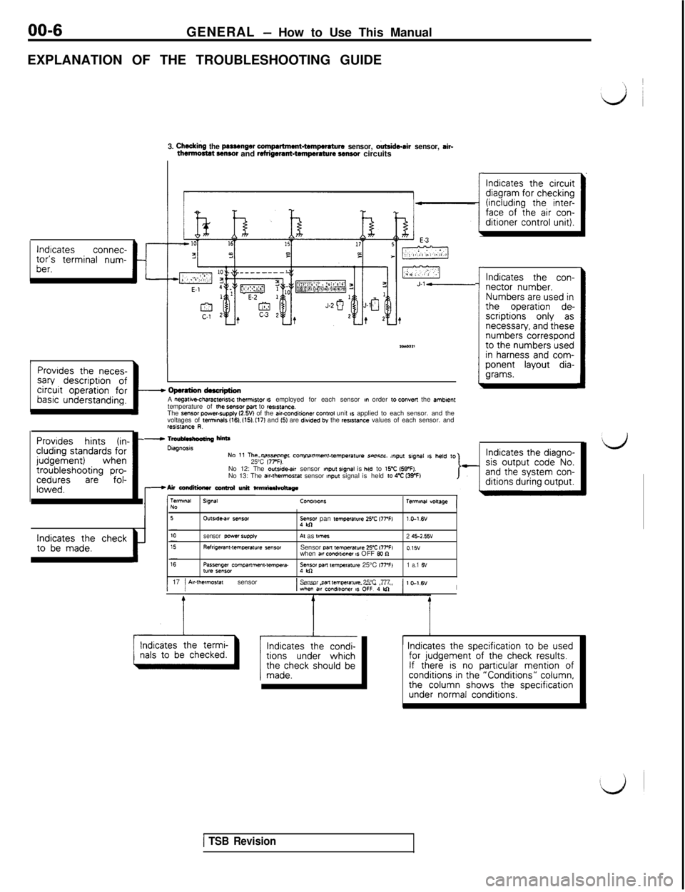
EXPLANATION OF THE TROUBLESHOOTING GUIDE
lndrcatesconnec-tor’s terminal num-ber.t
3. Cheddng the psssenger compartment-tempwsturs sensor, o&de-sir sensor, sir-thwtmctat CMSO~ and refrigerant-tempcmture sensor circuits
1.IProvides the neces-sary description ofcircuit operation forbasic understanding.I
Provides hints (in- -eluding standards forjudgement)whentroubleshooting pro-ceduresarefol-lowed.
- Opsrstion dnctiptionA negatkcharactensw fhemwor IS employed for each sensor nn order 10 convert the smbnen,temperature of rhe SB”SOf pan to ,es,s,ance.The sensor power-supply l2.W) of the air-condaioner control unit 1s applied to each sensor. and the
voltages of terminals 1161. 1151. I171 and 15) are divtded by the rwstance values of each sensor. andresislance R.
Indicates the checkto be made.t
-
I
Indicates the circuitdiagram for checking(including the inter-face of the air con-ditioner control unit).
Indicates the con-nector number.Numbers are used inthe operation de-scriptions only asnecessary, and thesenumbers correspondto the numbers usedin harness and com-ponent layout dia-grams.
- Tmublnkooting hff
NO 1, The DilFW+““P, P”m”il”m~“l.l~m~~=,,,,~ concnr ,w,p”t s,g”a, ,s ,,e,d ,o_ -____ .=_ __ .~_. .._... ._...r_._._._ ” -..--. ..,25°C 17rF).No 12: The outside-w sensor mput srgnal is he.----la to ,,“C IWFI.
-Air conditiuw ccnlml unit ta-.--* -.. No 13: The
awthwmos,a, sensor ~npu, signal isheld 10 4% IWF)l?mlMI “obuge
^I_I1Terminal) SWAW”IIWO”SNO
Dtagnosls
OUlYdedlr semorye pan ,emperatwe 25’C l77Wl.c-1.6v
sensor wwsr
SUPPI”Al as ,mlles2 45-2.55vRelngeran,.,emwrature *ensorSensor WR temperawe 25-Z 17PFI015”
when aar condwmer 1s OFF Bo nPassenger Compa*me”,-tempera.:“gol pm mnperat”re 25°C i77’FI1 a.1 6”lyre sensor
1 17 j Air-thermostat sensor1Sensor pan ,empelat”re 25°C ,777,I
’ Indicates the specification to be usedfor judgement of the check results.If there is no particular mention ofconditions in the “Conditions” column,the column shows the specificationunder normal conditions.
I
I
1 TSB Revision
Page 41 of 1146
GENERAL - Maintenance Service00-37
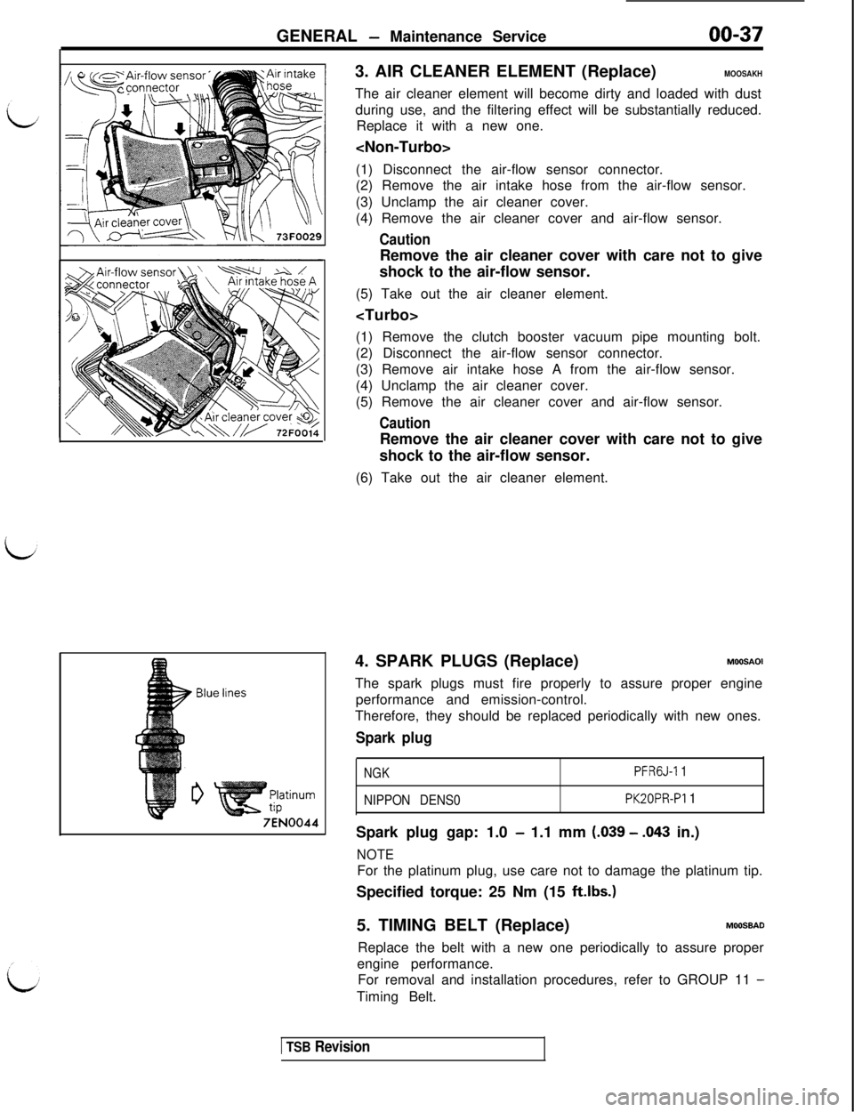
3. AIR CLEANER ELEMENT (Replace)
MOOSAKHThe air cleaner element will become dirty and loaded with dust
during use, and the filtering effect will be substantially reduced.
Replace it with a new one.
(1) Disconnect the air-flow sensor connector.
(2) Remove the air intake hose from the air-flow sensor.
(3) Unclamp the air cleaner cover.
(4) Remove the air cleaner cover and air-flow sensor.
CautionRemove the air cleaner cover with care not to give
shock to the air-flow sensor.
(5) Take out the air cleaner element.
(1) Remove the clutch booster vacuum pipe mounting bolt.
(2) Disconnect the air-flow sensor connector.
(3) Remove air intake hose A from the air-flow sensor.
(4) Unclamp the air cleaner cover.
(5) Remove the air cleaner cover and air-flow sensor.
CautionRemove the air cleaner cover with care not to give
shock to the air-flow sensor.
(6) Take out the air cleaner element.
4. SPARK PLUGS (Replace)
MOOSAOIThe spark plugs must fire properly to assure proper engine
performance and emission-control.
Therefore, they should be replaced periodically with new ones.
Spark plug
NGKPFRGJ-1 1
NIPPON DENS0
PK20PR-PI 1Spark plug gap: 1.0
- 1.1 mm LO39 - -043 in.)
NOTEFor the platinum plug, use care not to damage the platinum tip.
Specified torque: 25 Nm (15
ft.lbs.15. TIMING BELT (Replace)
MOOSBADReplace the belt with a new one periodically to assure proper
engine performance.
For removal and installation procedures, refer to GROUP 11
-Timing Belt.
1 TSB Revision
Page 48 of 1146
00-44
GENERAL - Main Sealant and Adhesive Table
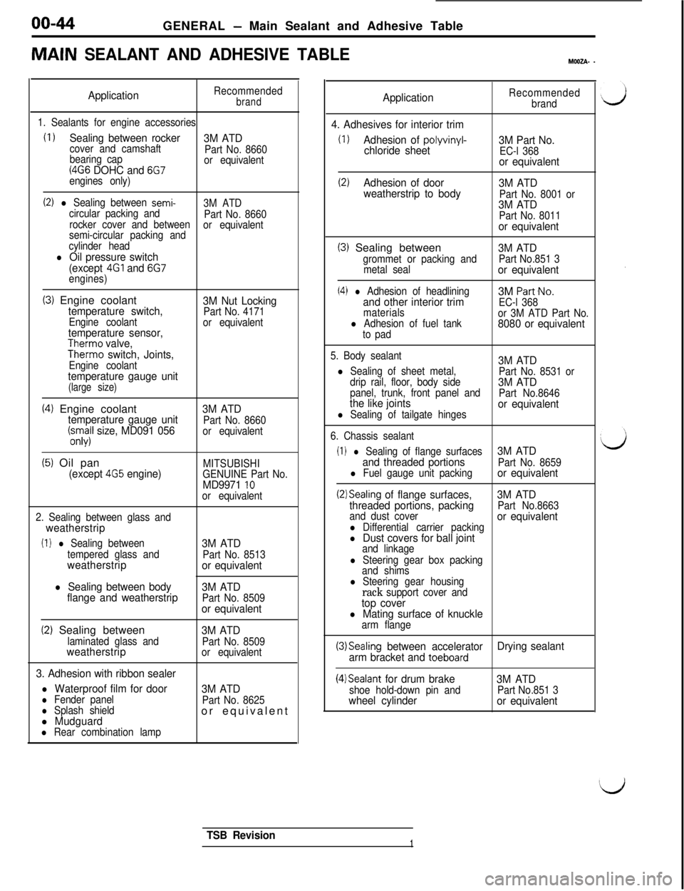
MAIN SEALANT AND ADHESIVE TABLEMWZA- -
ApplicationRecommendedbrand
1. Sealants for engine accessories
(I 1Sealing between rocker
3M ATDcover and camshaft
Part No. 8660
bearing cap
(4G6 DOHC and 6G7or equivalent
engines only)
(2) l Sealing between semi-3M ATD
circular packing and
Part No. 8660
rocker cover and between
semi-circular packing andor equivalent
cylinder head
l Oil pressure switch
(except 4Gl and 6G7engines)
(3) Engine coolanttemperature switch,Engine coolanttemperature sensor,Therm0 valve,Therm0 switch, Joints,Engine coolanttemperature gauge unit(large size)
3M Nut LockingPart No. 4171
or equivalent
(4) Engine coolanttemperature gauge unit(;.s;il size, MD091 0563M ATDPart No. 8660
or equivalent
(5) Oil pan(except 4G5 engine)MITSUBISHI
GENUINE Part No.
MD9971 10or equivalent
2. Sealing between glass and
weatherstrip
(I 1 l Sealing between
tempered glass and
weatherstrip
l Sealing between body
flange and weatherstrip3M ATD
Part No. 8513or equivalent
3M ATD
Part No. 8509or equivalent
(2) Sealing betweenlaminated glass andweatherstrip
3. Adhesion with ribbon sealer
l Waterproof film for doorl Fender panell Splash shieldl Mudguardl Rear combination lamp
3M ATDPart No. 8509
or equivalent
3M ATDPart No. 8625or equivalent
ApplicationRecommended
brand
4. Adhesives for interior trim
(1)Adhesion of polyvinyl-chloride sheet3M Part No.EC-l 368or equivalent
(2)Adhesion of door
3M ATD
weatherstrip to body
Part No. 8001 or3M ATDPart No. 8011or equivalent
(3) Sealing betweengrommet or packing and
metal seal
(4) l Adhesion of headliningand other interior trimmaterialsl Adhesion of fuel tank
to pad
3M ATDPart No.851 3or equivalent3M
Part-No.
EC-l 368
or 3M ATD Part No.
8080 or equivalent
5. Body sealant3M ATDl Sealing of sheet metal,
Part No. 8531 or
drip rail, floor, body side3M ATDpanel, trunk, front panel and
Part No.8646the like jointsl Sealing of tailgate hingesor equivalent
6. Chassis sealant
(I 1 l Sealing of flange surfaces3M ATD
and threaded portions
Part No. 8659l Fuel gauge unit packingor equivalent
(2)Sealing of flange surfaces,3M ATD
threaded portions, packingPart No.8663
and dust cover
l Differential carrier packingor equivalent
l Dust covers for ball jointand linkage
l Steering gear box packing
and shims
l Steering gear housingrack support cover andtop coverl Mating surface of knucklearm flange
(3)Sealing between accelerator
arm bracket and toeboardDrying sealant
(4)Sealant for drum brakeshoe hold-down pin andwheel cylinder3M ATDPart No.851 3or equivalent
TSB Revision1
Page 63 of 1146
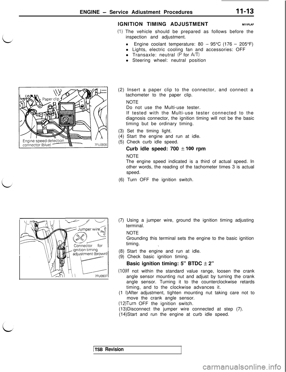
ENGINE - Service Adiustment ProceduresII-13
I_ ianltion tlminaI!H Connector for Igdpstment 6rown)
4tll II -7FUO9371IGNITION TIMING ADJUSTMENTMllFLAF
(1) The vehicle should be prepared as follows before the
inspection and adjustment.
lEngine coolant temperature: 80 - 95°C (176 - 205°F)
l Lights, electric cooling fan and accessories: OFF
l Transaxle: neutral
(P for A/T)l Steering wheel: neutral position
(2) Insert a paper clip to the connector, and connect a
tachometer to the paper clip.
NOTEDo not use the Multi-use tester.
If tested with the Multi-use tester connected to the
diagnosis connector, the ignition timing will not be the basic
timing but be ordinary timing.
(3) Set the timing light.
(4) Start the engine and run at idle.
(5) Check curb idle speed.
Curb idle speed: 700
f 100 rpm
NOTEThe engine speed indicated is a third of actual speed. In
other words, the reading of the tachometer times 3 is actual
speed.
(6) Turn OFF the ignition switch.
(7) Using a jumper wire, ground the ignition timing adjusting
terminal.
NOTEGrounding this terminal sets the engine to the basic ignition
timing.
\(8) Start the engine and run at idle.
(9) Check basic ignition timing.
Basic ignition timing: 5” BTDC
k 2”
(10)lf not within the standard value range, loosen the crank
angle sensor mounting nut and adjust by turning the crank
angle sensor. Turning it to the counterclockwise retards
timing, and to the clockwise advances it.
(1 l)After adjustment, tighten mounting nut taking care not to
move the crank angle sensor.
(12)Turn OFF the ignition switch.
(13)Disconnect the jumper wire connected at step (7).
(14)Start and run the engine at curb idle speed.
1 TSB Revision
Page 67 of 1146
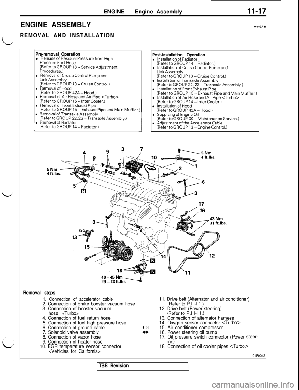
ENGINE - Engine AssemblyII-17
ENGINE ASSEMBLY
/REMOVAL AND INSTALLATION
I
Pre-removal Operationl Release of Residual Pressure from HighPressure Fuel Hose(Refer to GROUP 13 -Service AdjustmentProcedures,)l Removal of Cruise Control Pump andLink Assembly(Refer to GROUP 13 - Cruise Control.)l Removal of Hood(RefertoGROUP42A-Hood.)
l
Removal of Air Hose and Air Pipe
Post-installation Operationl Installation of Radiator(Refer to GROUP 14 - Radiator.)l Installation of Cruise Control Pump andLink Assembly(Refer to GROUP 13 -Cruise Control.)l Installation of Transaxle Assembly(Refer to GROUP 22,23 -Transaxle Assembly.)l lnstallatron of Front Exhaust Pipe(Refer to GROUP 15 - Exhaust Pipe and Main Muffler.)l Installation of Air Hose and Air Pipe
MllSA-B
4 ft.lbs.
6
40-45 Nm
29 - 33 fklbs.
Removal steps
1. Connection of accelerator cable11. Drive belt (Alternator and air conditioner)
2. Connection of brake booster vacuum hose(Refer to P.l l-l 1.)
3. Connection of booster vacuum12. Drive belt (Power steering)
hose
(Referto P.l l-l I.)4. Connection of fuel return hose13. Connection of alternator harness
5. Connection of fuel high pressure hose14. Oxygen sensor connector
6. Connection of ground cablel *15. Air conditioner compressor
7. Solenoid valve assembly4w
16. Power steering oil pump
8. Connection of vapor hose17. Oil pressure switch connector (Power steer-9. Connection of heater hoseing)10. EGR temperature sensor connector18. Connection of oil cooler pipes
OlFOO43
TSB Revision1
Page 68 of 1146
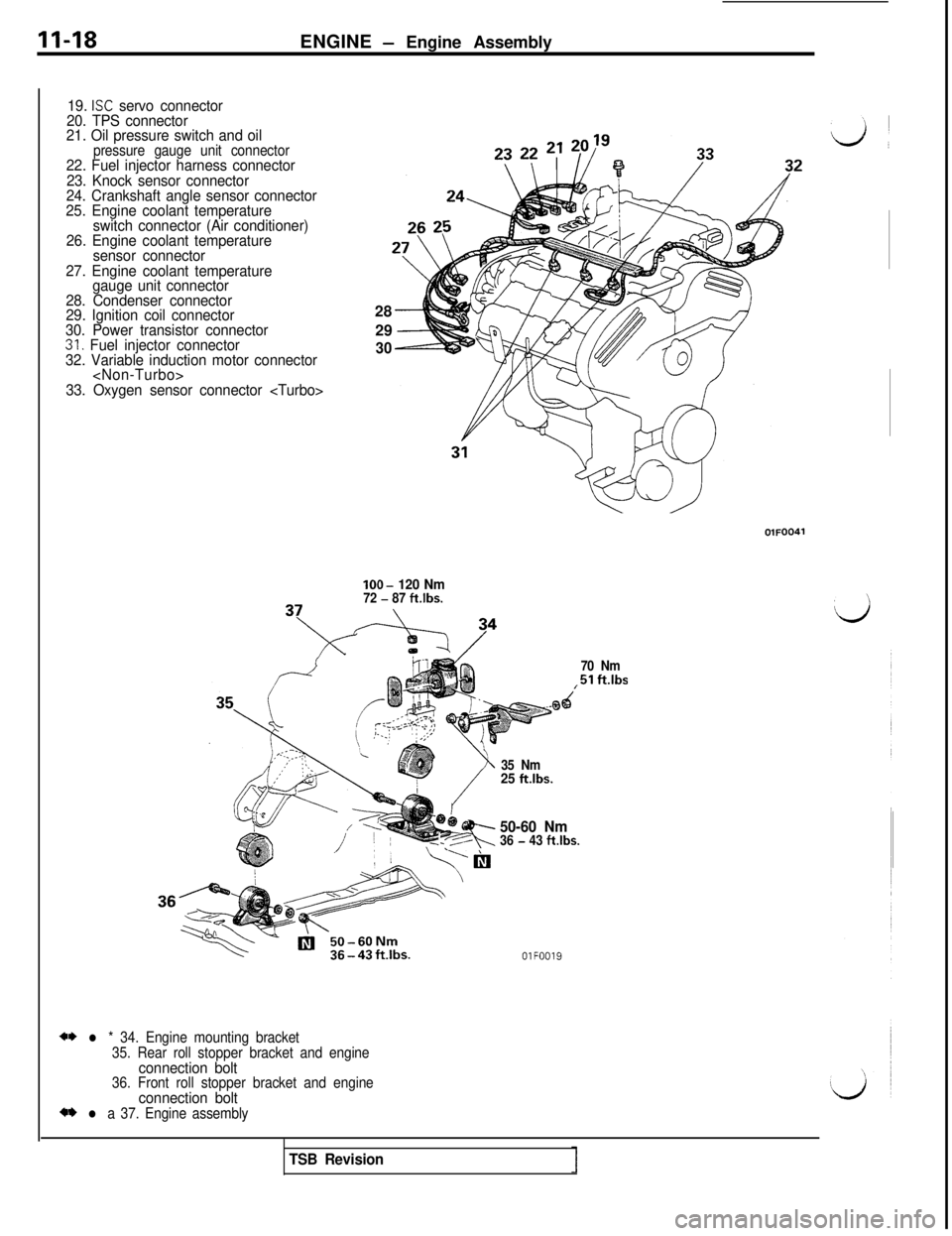
II-18ENGINE - Engine Assembly
19. ISC servo connector
20. TPS connector
21. Oil pressure switch and oil
pressure gauge unit connector22. Fuel injector harness connector
23. Knock sensor connector
24. Crankshaft angle sensor connector
25. Engine coolant temperature
switch connector (Air conditioner)
26. Engine coolant temperature
sensor connector
27. Engine coolant temperature
gauge unit connector
28. Condenser connector
29. Ignition coil connector
30. Power transistor connector
31. Fuel injector connector
32. Variable induction motor connector
33. Oxygen sensor connector
2930lOO-
120 Nm72 - 87 ft.lbs.
70 Nm
,51 ftlbs
** l * 34. Engine mounting bracket
35. Rear roll stopper bracket and engine
connection bolt36. Front roll stopper bracket and engineconnection bolt** l a 37. Engine assembly35 Nm
25 ft.lbs.
?I,---R
50-60 Nm36 - 43 ftlbs.
OlFOO19
TSB Revision
Page 76 of 1146
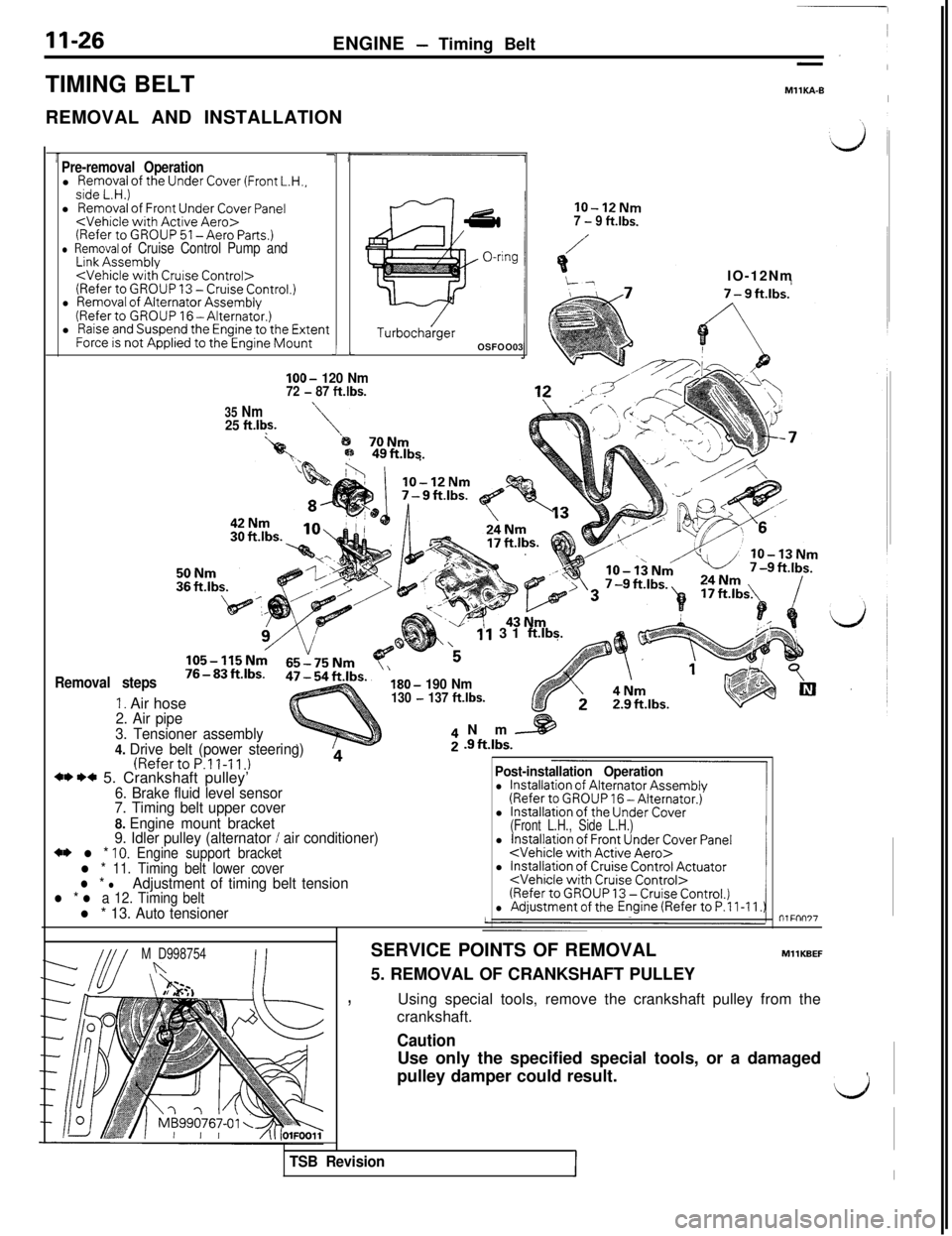
11-26ENGINE - Timing Belt
TIMING BELT
REMOVAL AND INSTALLATION
MllKA-BI
Pre-removal Operationl Removal of the Under Cover (Front L.H.,side L.H.)l Removal of Front Under Cover Panel
l Raise and Suspend the Engine to the ExtentForce is not Applied to the Engine Mounti LIOO-
120 Nm72 - 87 ft.lbs.
35 Nm25 ft.l$.
TurbochargerOSFOO03
lo-12Nm7 - 9 ft.lbs.
Removal steps
1. Air hose
11 31 ftlbs.
‘5IO-12Nm
B;p 49ftJbs.
\
180- 190 Nm130 - 137 ft.lbs.
2. Air pipe
3. Tensioner assembly
4. Drive belt (power steering)
(RefertoP.ll-11.)4** I)* 5. Crankshaft pulley’6. Brake fluid level sensor
7. Timing belt upper cover
8. Engine mount bracket
9. Idler pulley (alternator
/ air conditioner)+* l * 10. Engine support bracketl * 11. Timing belt lower coverl * lAdjustment of timing belt tensionl * l a 12. Timing beltl * 13. Auto tensionerNm
[email protected].
Post-installation Operation
l Installation of Alternator Assembly(Refer to GROUP 16 -Alternator.)
l Installation of the Under Cover(Front L.H., Side L.H.)l Installation of Front Under Cover Panel
l Installation of Cruise Control Actuator
M D998754nSERVICE POINTS OF REMOVAL
5. REMOVAL OF CRANKSHAFT PULLEYMllKBEF
,Using special tools, remove the crankshaft pulley from the
crankshaft.
TSB RevisionII
CautionUse only the specified special tools, or a damaged
pulley damper could result.
,
LJ
Page 81 of 1146
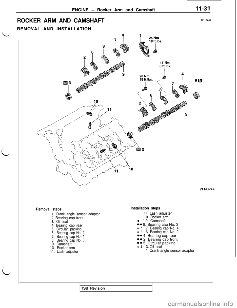
ENGINE - Rocker Arm and Camshaft11-31
ROCKER ARM AND CAMSHAFTREMOVAL AND INSTALLATION
11 Nm8 ftlbs.
MllZA-0
7EN0244
Removal steps
I. Crank angle sensor adaptor2. Bearing cap front3.Oil seal
4. Bearing cap rear
5.Circular packing6.Bearing cap No.27.Bearing cap No.4
8.Bearing cap No.3
9.Camshaft10.Rocker arm11.Lash adjuster
Installation steps
11. Lash adjuster10. Rocker arml * 9. Camshaft*a 8. Bearing cap No. 3l *7. Bearing cap No. 4l *6. Bearing cap No. 2** 4. Bearing cap rearI)* 2. Bearing cap front*+ 5. Circular packingl 43. Oil sealI. Crank angle sensor adaptor
TSB Revision
Page 103 of 1146
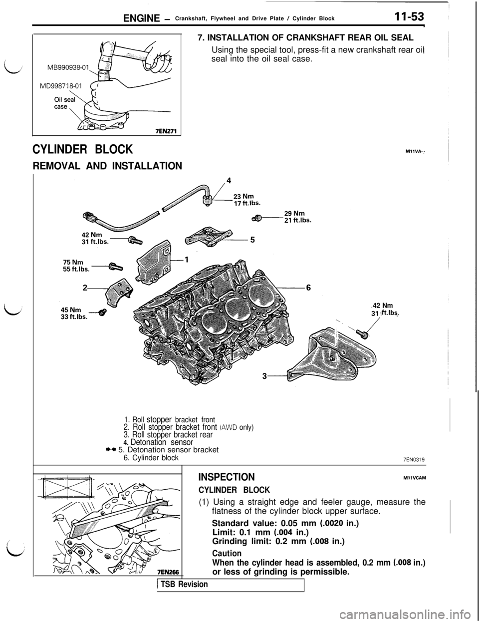
ENGINE -Crankshaft, Flywheel and Drive Plate / Cylinder Block11-53
MB990938-01
CYLINDER BLOCK
REMOVAL AND INSTALLATION7. INSTALLATION OF CRANKSHAFT REAR OIL SEAL
Using the special tool, press-fit a new crankshaft rear oil
seal into the oil seal case.MllVA--
42 Nmftlbs.
1. Roll stopper bracket front2. Roll stopper bracket front (AWD only)3. Roll stopper bracket rear4. Detonation sensorI)* 5. Detonation sensor bracket
6. Cylinder block7EN0319
INSPECTION
CYLINDER BLOCK
MllVCAM(1) Using a straight edge and feeler gauge, measure the
flatness of the cylinder block upper surface.
Standard value: 0.05 mm
(-0020 in.)
Limit: 0.1 mm
(.004 in.)
Grinding limit: 0.2 mm
(.008 in.)
Caution
When the cylinder head is assembled, 0.2 mm (.008 in.)or less of grinding is permissible.
1 TSB Revision