fuse chart MITSUBISHI 3000GT 1991 Service Manual
[x] Cancel search | Manufacturer: MITSUBISHI, Model Year: 1991, Model line: 3000GT, Model: MITSUBISHI 3000GT 1991Pages: 1146, PDF Size: 76.68 MB
Page 748 of 1146

35-26SERVICE BRAKES -Anti-lock Braking System TroubleshootingI
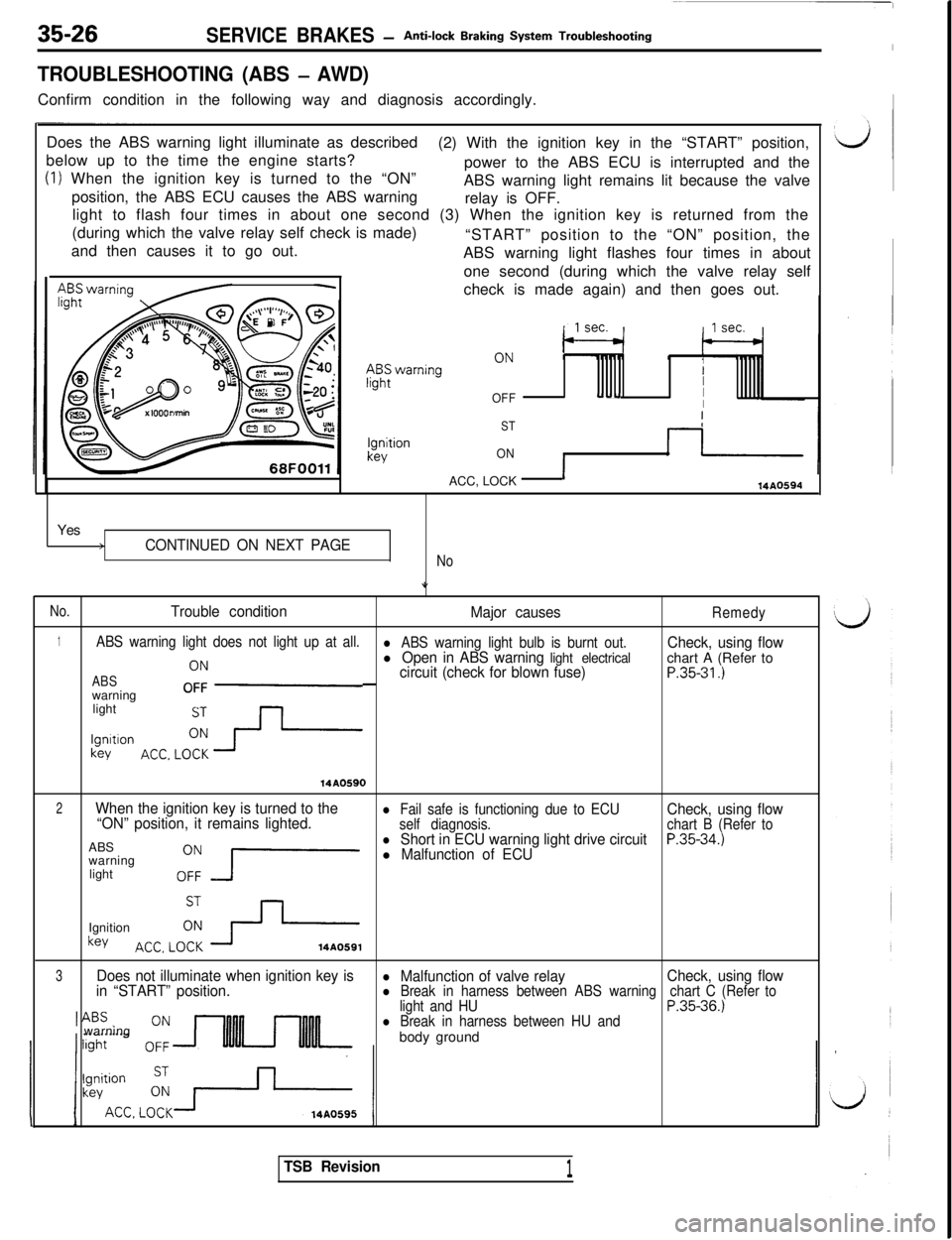
TROUBLESHOOTING (ABS - AWD)Confirm condition in the following way and diagnosis accordingly.
Does the ABS warning light illuminate as described
below up to the time the engine starts?(2) With the ignition key in the “START” position,
(1) When the ignition key is turned to the “ON”power to the ABS ECU is interrupted and the
position, the ABS ECU causes the ABS warningABS warning light remains lit because the valve
relay is OFF.
light to flash four times in about one second (3) When the ignition key is returned from the
(during which the valve relay self check is made)
and then causes it to go out.“START” position to the “ON” position, the
ABS warning light flashes four times in about
one second (during which the valve relay self
-check is made again) and then goes out.
III
OFFu--I-II
ST
ONACC, LOCK
114A0594Yes
>CONTINUED ON NEXT PAGE
No
No.
Trouble condition
Major causesRemedy
1ABS warning light does not light up at all.l ABS warning light bulb is burnt out.
ACC,LOb--
l Open in ABS warning light electricalCheck, using flowchart A (Refer to
ABScircuit (check for blown fuse)P.35-31.)warningOFFlight
lgmtlon
key
14AO590
2When the ignition key is turned to the
“ON” position, it remains lighted.l Fail safe is functioning due to ECU
self diagnosis.Check, using flowchart B (Refer toABS,“,F
J-l Short in ECU warning light drive circuitP.35-34.)warningl Malfunction of ECUlight
Ignition
key.;i,LOi h
3Does not illuminate when ignition key is
in “START” position.l Malfunction of valve relayl Break in harness between ABS warningCheck, using flowchart C (Refer to
light and HUP.35-36.)l Break in harness between HU andwarning
body ground
TSB Revision1
Page 1052 of 1146

52B-42 SUPPLEMENTAL RESTRAINT SYSTEM (SRS) - Troubleshooting
MB991349
SRS Check Harness
View ASRS Check Harness connector @
16R2188
Fuse’No. 18Ground
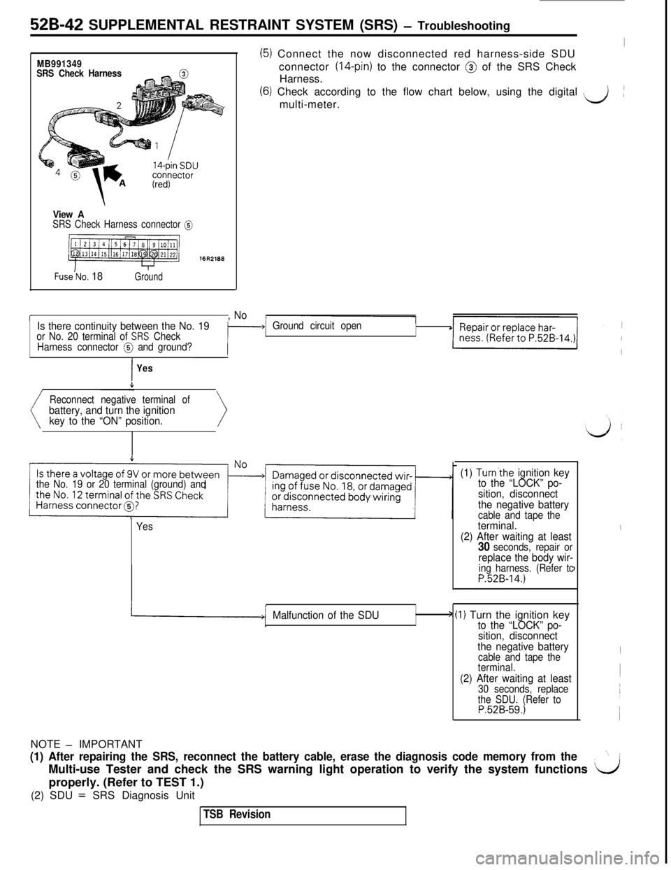
(5) Connect the now disconnected red harness-side SDUIconnector
(14-pin) to the connector @ of the SRS Check
Harness.
(6) Check according to the flow chart below, using the digital ‘&multi-meter.(
r, No
Is there continuity between the No. 19
or No. 20 terminal of SRS Check
Harness connector @ and ground?Ground circuit open
IYes
Reconnect negative terminal of
battery, and turn the ignition
key to the “ON” position.
the No. 19 or 20 terminal (ground) and
Yes
(1) Turn’the ignition key
to the “LOCK” po-
sition, disconnect
the negative battery
cable and tape theterminal.
(2) After waiting at least
30 seconds, repair orreplace the body wir-ing harness. (Refer tcP.52B-14.)
I
I
Malfunction of the SDU> (I) Turn the ignition keyto the “LOCK” po-
sition, disconnect
the negative battery
cable and tape the
terminal.
(2) After waiting at least30 seconds, replace
the SDU. (Refer to
P.52B-59.)NOTE
- IMPORTANT
(1) After repairing the SRS, reconnect the battery cable, erase the diagnosis code memory from the”~
Multi-use Tester and check the SRS warning light operation to verify the system functions
L/1properly. (Refer to TEST 1.)
(2) SDU
= SRS Diagnosis Unit
TSB Revision
Page 1054 of 1146

52B-44 SUPPLEMENTAL RESTRAINT SYSTEM (SRS) - Troubleshooting
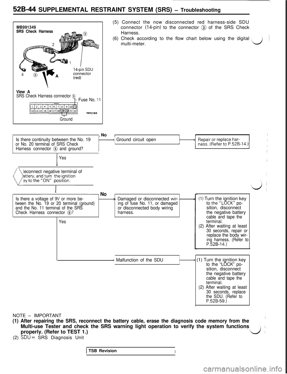
MB991349SRS Check Harness(5) Connect the now disconnected red harness-side SDU
connector (14-pin) to the connector @ of the SRS Check
Harness.
(6) Check according to the flow chart below using the digital
> ~
multi-meter.d
View ASRS Check Harness connector @t- Fuse No. 11
Ground
/, NoIs there continuity between the No. 19or No. 20 terminal of SRS Checki- Ground circuit open1
Harness connector @ and ground?i
I
Yes
Reconnect negative terminal of
( py;;;;fgJ;p ~~y~~on>
- NoIs there a voltage of 9V or more be-> Damaged or disconnected wir-tween the No. 19 or 20 terminal (ground)
and the No. 11 terminal of the SRSing of fuse No. 11, or damaged
Check Harness connector
@?or disconnected body wiringharness.
Yes
(1) Turn the ignition keyto the.“LOCK” po-
sition, disconnect
the negative battery
cable and tape the
terminal.
(2) After waiting at least30 seconds, repair orreplace the body wir-ing harness. (Refer toP.52B-14.)
) Malfunction of the SDU> (1) Turn the ignition keyto the “LOCK” po-
sition, disconnect
the negative battery
cable and tape the
terminal.
(2) After waiting at least30 seconds, replace
the SDU. (Refer to
P.52B-59.)
1 TSB RevisionINOTE
- IMPORTANT
(1) After repairing the SRS, reconnect the battery cable, erase the diagnosis code memory from the’Multi-use Tester and check the SRS warning light operation to verify the system functions
\iproperly. (Refer to TEST 1.)
d(2)
SDU = SRS Diagnosis Unit
Page 1122 of 1146

55-40FULL AUTO AIR CONDITIONER - Troubleshooting
FULL AUTO AIR CONDITIONER
TROUBLESHOOTINGM55ECAF
TROUBLESHOOTING PROCEDUREd
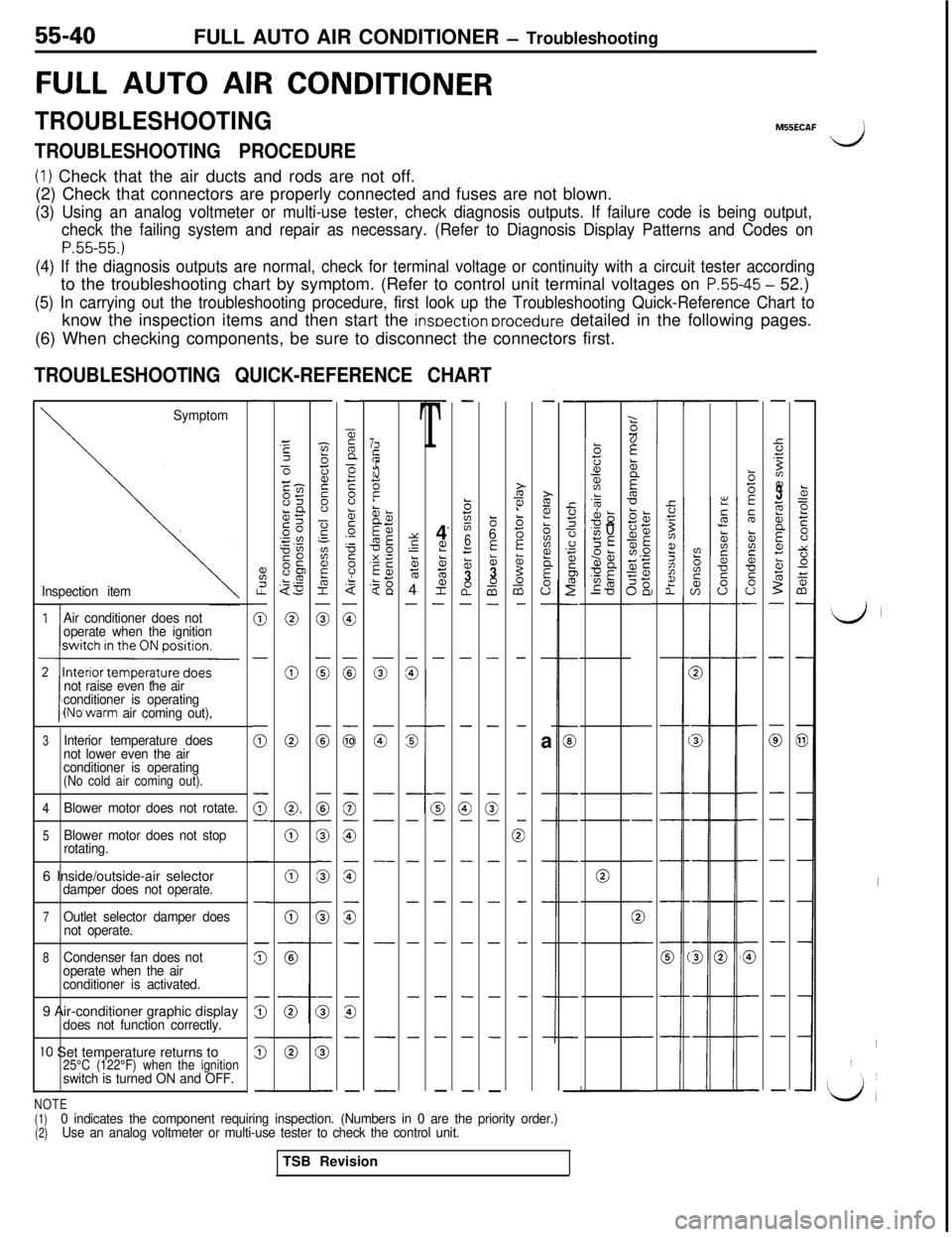
(1) Check that the air ducts and rods are not off.
(2) Check that connectors are properly connected and fuses are not blown.
(3) Using an analog voltmeter or multi-use tester, check diagnosis outputs. If failure code is being output,
check the failing system and repair as necessary. (Refer to Diagnosis Display Patterns and Codes on
P.55-55.)
(4) If the diagnosis outputs are normal, check for terminal voltage or continuity with a circuit tester accordingto the troubleshooting chart by symptom. (Refer to control unit terminal voltages on
P.55-45 - 52.)
(5) In carrying out the troubleshooting procedure, first look up the Troubleshooting Quick-Reference Chart toknow the inspection items and then start the
insoection orocedure detailed in the following pages.
(6) When checking components, be sure to disconnect the connectors first.
TROUBLESHOOTING QUICK-REFERENCE CHART
-
%I.?
0
-
(i;
0-
-
-
z
s
5
-
z3Ec-l-cm85LQgc .”0”SO0s“E$3
0
0
0
0.
0
0
0
-
-zbij2s”
-?‘-
aF&I
0
0
0
0
0
0
G
-
s
5
-
-
55n
>F8b5.-
F
8.$
0
:
G
0
G
is
z
-
G-
-
-
-
T4
L??ctE;
2-
-
-
G-
-
-
-
-
-
-.
-
b725
6
f53a0-
-
-
G-
-
-
-
-
-
-
86
E&3-0a-
-
-
-
3-
-
-
-
-
-
-
-
i?i?!
biiz?
E
0”-
-a
-
-
-
-
-
-
-
GE
21z6:1D-
-
-
-
-
0
-
-
-
-
-
;(if
zzit
5
5‘dTC
T-
-:
2
2
::ii3z;
2%;sjE1.0
;g5E
-
:
,,
,
1
-
-
-
-
0
-
-
-
-
-
k=eE00
t:0+i
-
-
a
-
-
-
-
-
-
-
-
b5E
5
&is*
s0-
-
-
-
-
-
-
G
-
-
-
-
5.T
Bz??3;i;b
Ecz
5-
-
0
-
-
-
-
-
-
-
-
1
225cn-
s
s----
s---
Symptom
Inspection item
7i;if
II:.?t.!
1E5z
iT-a,?z
5g< 13;$
zg
z
G-
-
-
-
-
-
-
.k?alL-0s
‘v, 0SE95anUE
ma‘0Y
s‘-5764
-
-
%G
-
-
-
-
-
-
-
Air conditioner does not
operate when the ignition
not raise even the air
conditioner is operating
(No’warm air coming out).
LJ
I
I~
‘L/,
3Interior temperature does
not lower even the air
conditioner is operating
(No cold air coming out).
4
Blower motor does not rotate.
5Blower motor does not stop
rotating.
06 Inside/outside-air selectordamper does not operate.
7Outlet selector damper does
not operate.
8Condenser fan does not
operate when the air
conditioner is activated.9 Air-conditioner graphic display
does not function correctly.
IO Set temperature returns to25°C (122°F) when the ignitionswitch is turned ON and OFF.
NOTE(1)
(2)0 indicates the component requiring inspection. (Numbers in 0 are the priority order.)
Use an analog voltmeter or multi-use tester to check the control unit.TSB Revision