sensor MITSUBISHI 3000GT 1991 Owner's Manual
[x] Cancel search | Manufacturer: MITSUBISHI, Model Year: 1991, Model line: 3000GT, Model: MITSUBISHI 3000GT 1991Pages: 1146, PDF Size: 76.68 MB
Page 120 of 1146
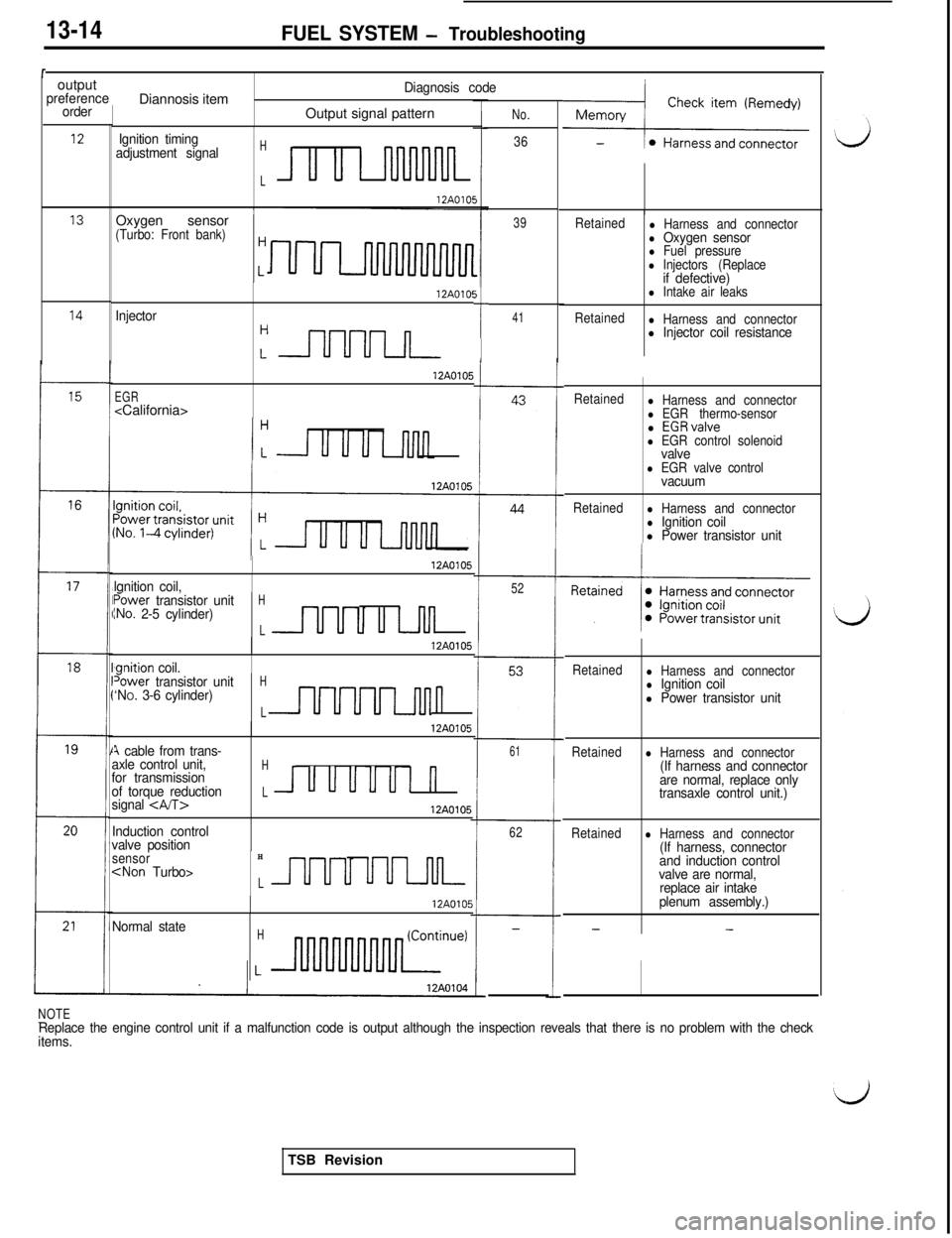
13-14FUEL SYSTEM - Troubleshooting
routput
preference
order
7Diannosis item
Diagnosis code
IOutput signal patternNo.
36
39
121 Ignition timing
adjustment signalH
L
13Oxygen sensor ’(Turbo: Front bank)HRetainedl Harness and connectorl Oxygen sensorl Fuel pressurel Injectors (Replaceif defective)l Intake air leaks
Retained
l Harness and connectorl Injector coil resistance
5
I--
Injector12AOlO!
:nnnn
EGR
12A0105
14
41
Retainedl Harness and connectorl EGR thermo-sensorl EGRvalvel EGR control solenoidvalvel EGR valve controlvacuum
Retainedl Harness and connectorl Ignition coill Power transistor unit
16
lqnition coil,
12A0105
52power transistor unitINO. 2-5 cylinder)H
Lu Lnll
‘qnition coil.
12AO105
18Retainedl Harness and connectorl Ignition coill Power transistor unit
Retainedl Harness and connector(If harness and connector
are normal, replace only
transaxle control unit.)
Retainedl Harness and connector(If harness, connector
and induction control
valve are normal,
replace air intake
plenum assembly.)
--
Tower transistor unitH‘NO. 3-6 cylinder)
Ln
12A0105
A cable from trans-
axle control unit,Hfor transmission
of torque reductionLUUUUUI n
signal 12A0105
Induction control
valve position
61
62
sensorH
12A0105
Normal stateH-
NOTE-Replace the engine control unit if a malfunction code is output although the inspection reveals that there is no problem with the check
items.TSB Revision
Page 126 of 1146
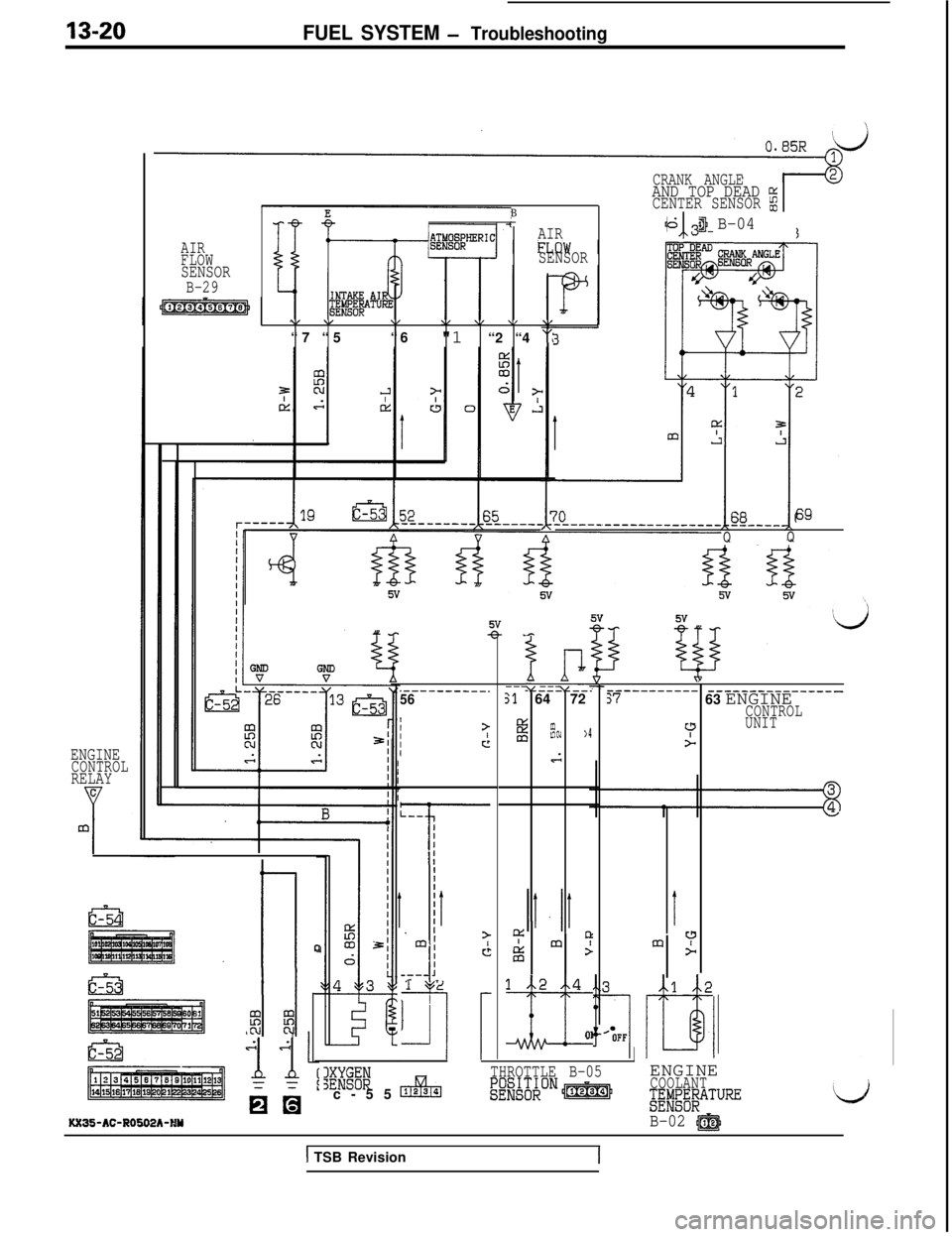
13-20FUEL SYSTEM - Troubleshooting
CRANK ANGLEAND TOP DEAD z
BCENTER SENSOR $j
AIR4-j B-04613
SENSOR
\/ v\/\, \I \/\I“7 “5“6
"1 “2 “4 “l
AIR
FLOW
SENSORB-29
69
QQ
ip--------.Sl6472
4:g$w cu> 4
d
m95
”----------- __---------_____:763 ENGINECONTROL?UNIT>
I
m?>
.----------.56
III?IcIENGINECONTROLRELAYc
Y
mL--I
1;
III
jr
I>ml
-II
d
--- 11 2
I
~~
12 4
~01
Ii%ml
c-55
c&m
THROTTLE B-05ENGINE
~~~Q~~oNp&q+COOLANT$E!E$BATURELj
B-02 @J
.h
0
I I
$I I$KX35-AC-R0502h-HY
1 TSB Revision
Page 130 of 1146
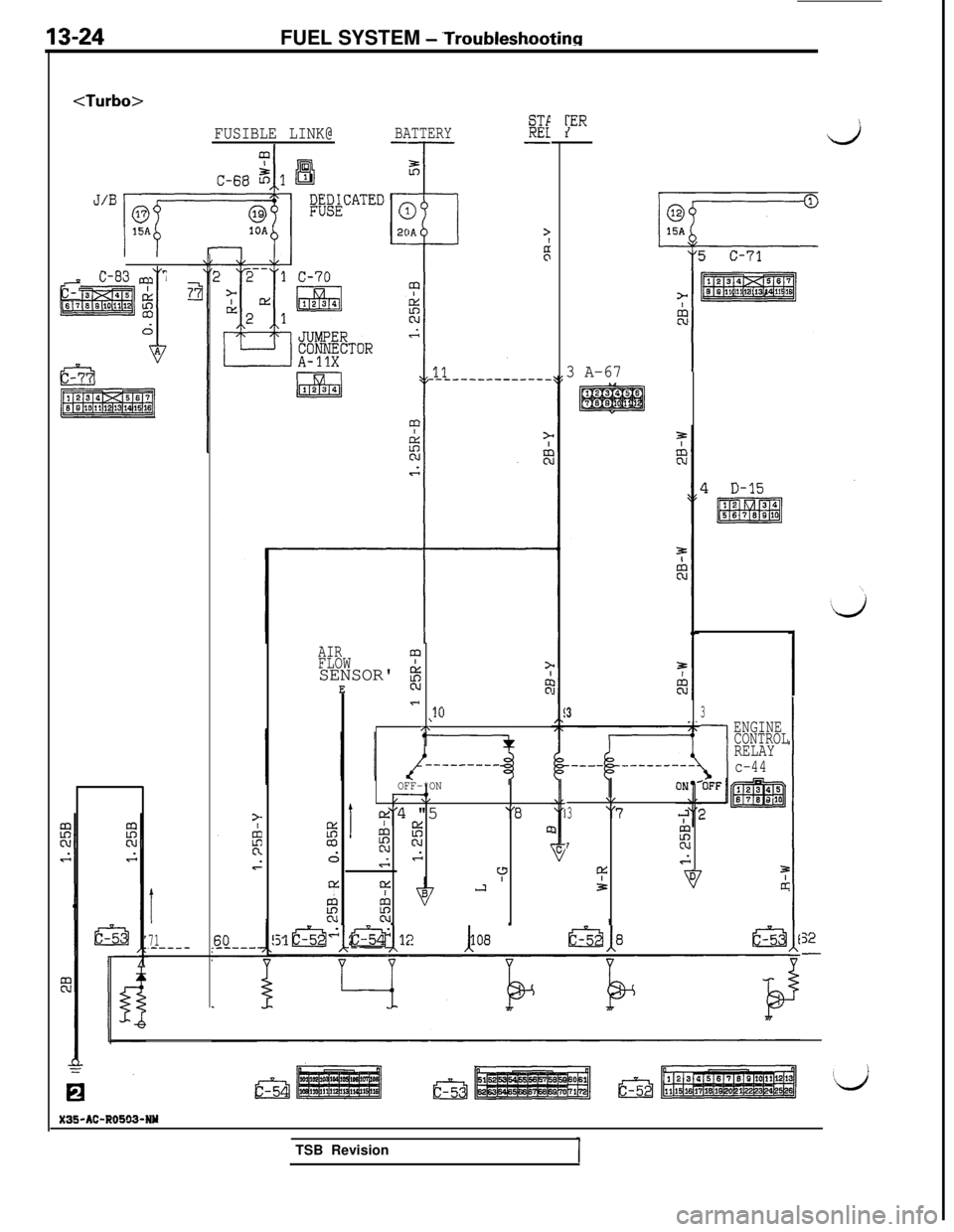
13-24FUEL SYSTEM - ‘Troubleshootinn
FUSIBLE LINK@BATTERY%
--T-- -J/Bqa1
B;&CATED
;ER
0
1
15A
c-71
I-
jLEl3za
12345675 s *01112* , 1616
w
15A
I t
IOA
-1l-
C-83 m 7
pTEiEsq&is
1
6
Efi;;l
p!i!Ezq;
3 A-67
I
71,-----
AIRmFLOWSENSOR' i?
EN:
- ,lOI\
---------
OFF-*ON__O/ \I
1
cte"4 "5"0%
%D
dN INGlc
CLYYIJ
EN
33
-I
ENGINE
CONTROL
RELAY
c-44
\,
3"7
T!c
4:?3[II
1-;125 +2a 108 &1852-5
X35-AC-R0503-NY
EaaTSB Revision
Page 132 of 1146
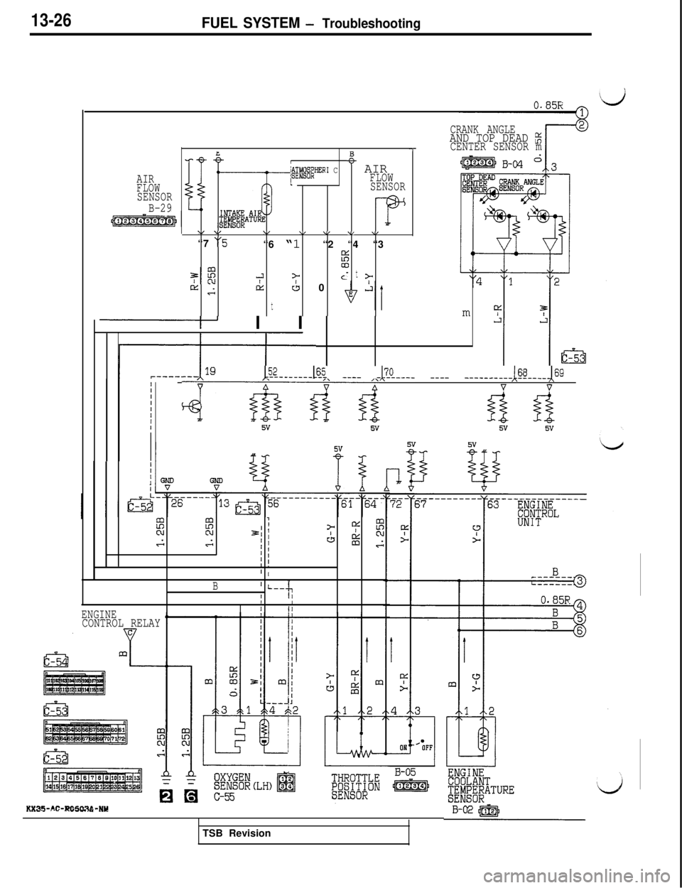
13-26FUEL SYSTEM - Troubleshooting
AIR
FLOW
SENSOR
B-29
LB-eI~@.@JER’ C+- AIRIFLOW
SENSOR
\/ v\/\/ \/ \I \,“7
“5“6 “1 “2 “4 “3
%
7:
00-3>t
Ac- z-rtis
t
CL 0
I I I
iIIIIIIII
III1I
~ZL---&i ____ -&L--- ____ --------&----&9
4&&d vv
CRANK ANGLEAND TOP DEAD z-7CENTER SENSOR mm
2E?7IN21 )= 4:EGGI ’CL g
) 1G
I !’ I
B’ L--l‘;rII
ENGINEIII
CONTROL RELAY
5vii
KX35-AC-RO5tX36-NYTSB Revision
Page 139 of 1146
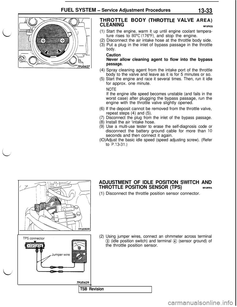
FUEL SYSTEM - Service Adjustment Procedures13-33THROTTLE BODY
(THROTrLE VALVE AREA)
CLEANINGM13FICS
(1) Start the engine, warm it up until engine coolant tempera-ture rises to
80°C (176”F), and stop the engine.
(2) Disconnect the air intake hose at the throttle body side.
(3) Put a plug in the inlet of bypass passage in the throttle
body.
CautionNever allow cleaning agent to flow into the bypass
passage.(4) Spray cleaning agent from the intake port of the throttle
body to the valve and leave as it is for 5 minutes or so.
(5) Start the engine and race it several times. Then, run it idlefor approx. one minute.
NOTE
If the engine idle speed becomes unstable (and fails in theworst case) after plugging the bypass passage, run the
engine with the throttle valve slightly opened.
(6) If the deposit cannot be removed from the throttle valve,
repeat steps (4) and (5).
(7) Disconnect the plug from the inlet of the bypass passage.(8) Install the air ‘intake hose.
(9) Use a multi-use tester to erase the self-diagnosis code ordisconnect the battery ground cable for more than
IOseconds and then connect it again.
(lO)Adjust the basic idle speed (speed adjusting screw). (Referto
P.13-31.)
7FUO629
ADJUSTMENT OF IDLE POSITION SWITCH AND
THROTTLE POSITION SENSOR (TPS)M13FIFA(1) Disconnect the throttle position sensor connector.
(2) Using jumper wires, connect an ohmmeter across terminal
@ (idle position switch) and terminal @ (sensor ground) ofthe throttle position sensor.
TSB Revision
Page 140 of 1146
FUEL SYSTEM - Service Adjustment Procedures
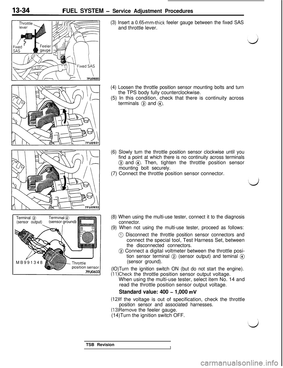
(3) Insert a 0.65-mm-thick feeler gauge between the fixed SASand throttle lever.
Terminal @
(sensor output)zensor g&nd)MB991348
1
(4) Loosen the throttle position sensor mounting bolts and turnthe TPS body fully counterclockwise.
(5) In this condition, check that there is continuity across
terminals
@ and @.
(6) Slowly turn the throttle position sensor clockwise until you
find a point at which there is no continuity across terminals
@ and 0. Then, tighten the throttle position sensor
mounting bolt securely.(7) Connect the throttle position sensor connector.
(8) When using the multi-use tester, connect it to the diagnosis
connector.
(9) When not using the multi-use tester, proceed as follows:
@ Disconnect the throttle position sensor connectors andconnect the special tool, Test Harness Set, between
the disconnected connectors.
@ Connect a digital voltmeter between the throttle posi-
tion sensor terminal @ (sensor output) and teminal @
(sensor ground).
(lO)Turn the ignition switch ON (but do not start the engine).
(IlKheck the throttle position sensor output voltage.
When using the multi-use tester, select item No. 14 and
read the throttle position sensor output voltage.
Standard value: 400 - 1,000 mV
(12)lf the voltage is out of specification, check the throttle
position sensor and associated harnesses.
(13)Remove the feeler gauge.
(14)Turn the ignition switch OFF.
TSB Revision
1
Page 141 of 1146
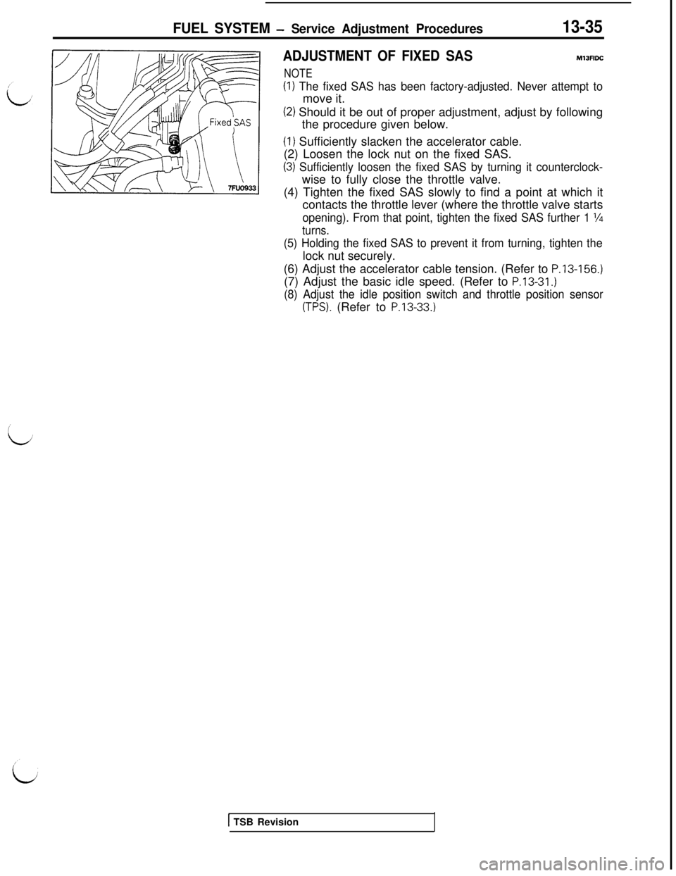
FUEL SYSTEM - Service Adjustment Procedures13-35
ADJUSTMENT OF FIXED SASMlJFlDC
NOTE
(1) The fixed SAS has been factory-adjusted. Never attempt tomove it.
(2) Should it be out of proper adjustment, adjust by following
the procedure given below.(I) Sufficiently slacken the accelerator cable.
(2) Loosen the lock nut on the fixed SAS.
(3) Sufficiently loosen the fixed SAS by turning it counterclock-wise to fully close the throttle valve.
(4) Tighten the fixed SAS slowly to find a point at which it
contacts the throttle lever (where the throttle valve starts
opening). From that point, tighten the fixed SAS further 1 l/4
turns.
(5) Holding the fixed SAS to prevent it from turning, tighten thelock nut securely.
(6) Adjust the accelerator cable tension. (Refer to
P.13-156.)(7) Adjust the basic idle speed. (Refer to
P.13-31.)
(8) Adjust the idle position switch and throttle position sensor
(TPS). (Refer to P.13-33.)
1 TSB Revision
Page 142 of 1146
13-36FUEL SYSTEM - 0
n-vehicle Inspection of MPI Components
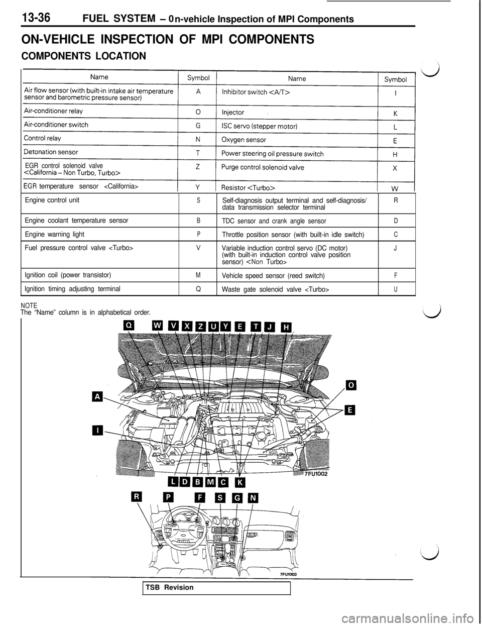
ON-VEHICLE INSPECTION OF MPI COMPONENTS
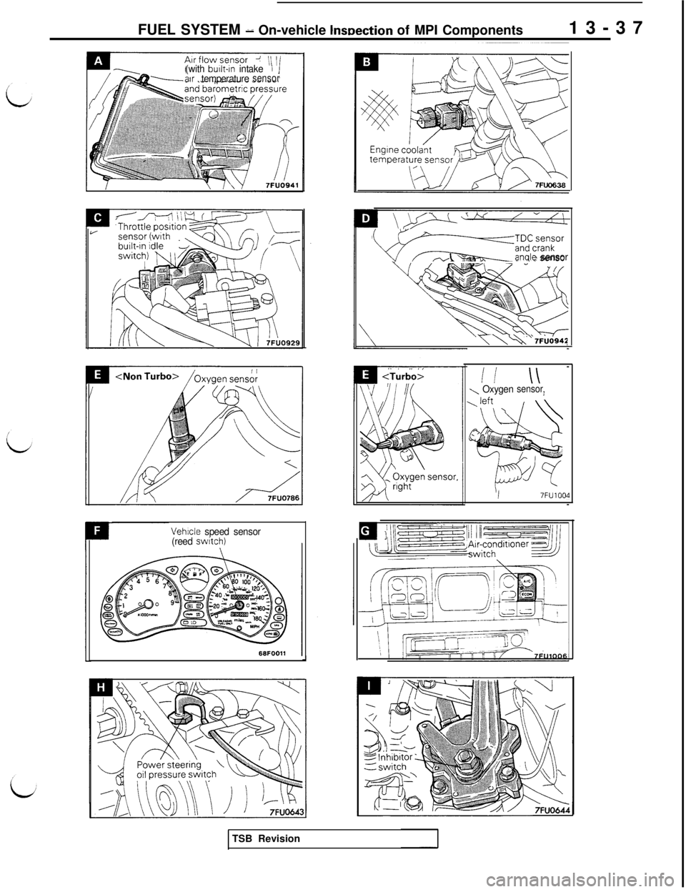
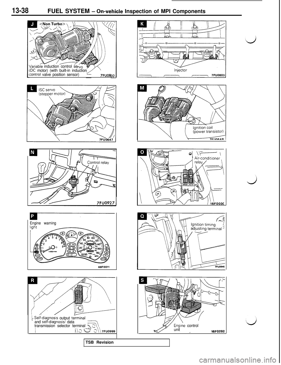
COMPONENTS LOCATION
EGR control solenoid valve
temperature sensor
Engine control unit
Engine coolant temperature sensor
Engine warning light
Fuel pressure control valve
Ignition coil (power transistor)
Ignition timing adjusting terminal
SSelf-diagnosis output terminal and self-diagnosis/Rdata transmission selector terminal
BTDC sensor and crank angle sensorD
PThrottle position sensor (with built-in idle switch)C
vVariable induction control servo (DC motor)J(with built-in induction control valve position
sensor)
MVehicle speed sensor (reed switch)F
QWaste gate solenoid valve
NOTEThe “Name” column is in alphabetical order.TSB Revision
Page 143 of 1146
FUEL SYSTEM d On-vehicle lnwection of MPI Components13-37(with built-in intakeIair temperaturesensor
Vehicle speed sensor
(reed switch)J
wF~~::~:~~or- A.anale sensor
y\\ v 7Fbd942
ii \\\ Oxygensensor,
I7FU1004
//
\:/TSB Revision
Page 144 of 1146
13-38FUEL SYSTEM - Onaehicle Inspection of MPI Components
I/ariableinduction control se:DC motor) (with built-in induction:ontrol valve position sensor)7FUO8
Engine warning
1 Self-diagn,osls output terminal
and self-dlagnosisi data
transmission selector terminal T37
h\s e >\\ 7FUO999Engiie
control
unit
I16FO292TSB Revision