sensor MITSUBISHI 3000GT 1991 Workshop Manual
[x] Cancel search | Manufacturer: MITSUBISHI, Model Year: 1991, Model line: 3000GT, Model: MITSUBISHI 3000GT 1991Pages: 1146, PDF Size: 76.68 MB
Page 169 of 1146
id
LFUEL SYSTEM
- On-vehicle Inspection of MPI Components13-63
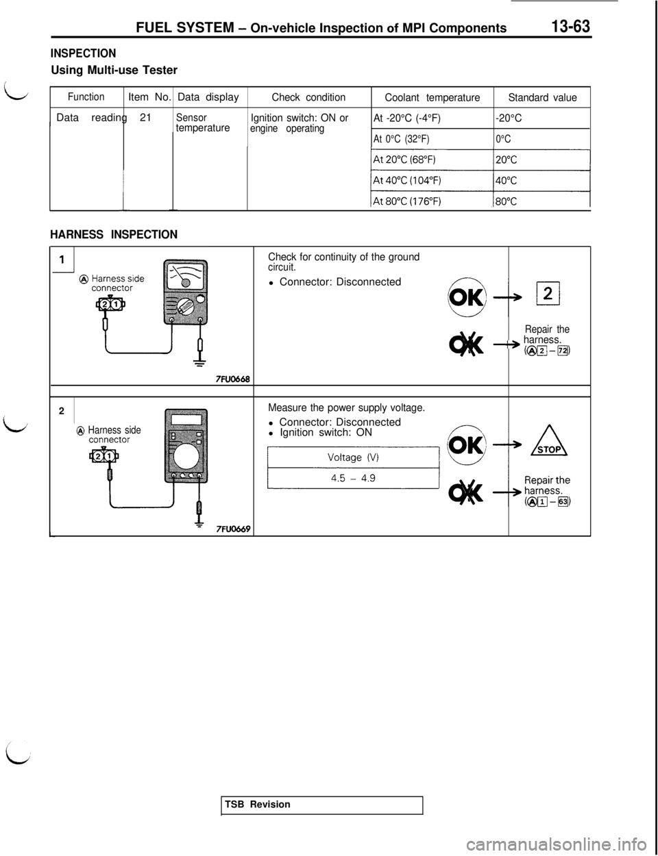
INSPECTIONUsing Multi-use Tester
LFunctionItem No. Data displayCheck condition
Coolant temperatureStandard valueData reading 21
SensorIgnition switch: ON or
At -20°C (-4°F)-20°C
temperatureengine operatingAt 0°C (32°F)0°C
HARNESS INSPECTION
Check for continuity of the groundcircuit.l Connector: Disconnected
Repair the---+ harness.
7FUO6682
Measure the power supply voltage.l Connector: Disconnected
@ Harness sidel Ignition switch: ON
7FUO669TSB Revision
Page 170 of 1146
13-64FUEL SYSTEM - 0
n-vehicle Inspection of MPI Components
7FUO670
Apply sealant
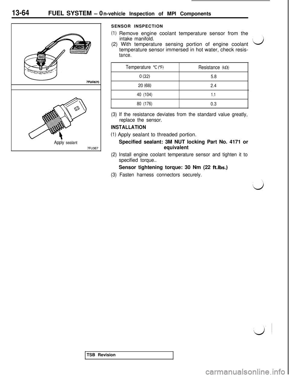
7FUO67’SENSOR INSPECTION
(1) Remove engine coolant temperature sensor from the
intake manifold.(2) With temperature sensing portion of engine coolant
temperature sensor immersed in hot water, check resis-
tance.
Temperature
“C (“F)Resistance (kCI)
0 (32)5.8
20 (68)2.4
40 (104)1.1
80 (176)0.3
(3) If the resistance deviates from the standard value greatly,
replace the sensor.
INSTALLATION
(1) Apply sealant to threaded portion.
Specified sealant: 3M NUT locking Part No. 4171 or
equivalent
(2) Install engine coolant temperature sensor and tighten it to
specified torque..Sensor tightening torque: 30 Nm (22
ft.lbs.)
(3) Fasten harness connectors securely.TSB Revision
Page 171 of 1146
FUEL SYSTEM - On-vehicle Inspection of MPI Components13-65
i
1
THROTTLE POSITION SENSORM13YJAC
Maximum
Throttle shaft
turning angle
162481
Minlmum
@ Unleaded
Equipment side
connectorThrottle positron sensor
I
@ Harness side
connector
Ii
SEL14001
Engine control unit ,
I
Engine control unit connector
7FUO672
7FUO653
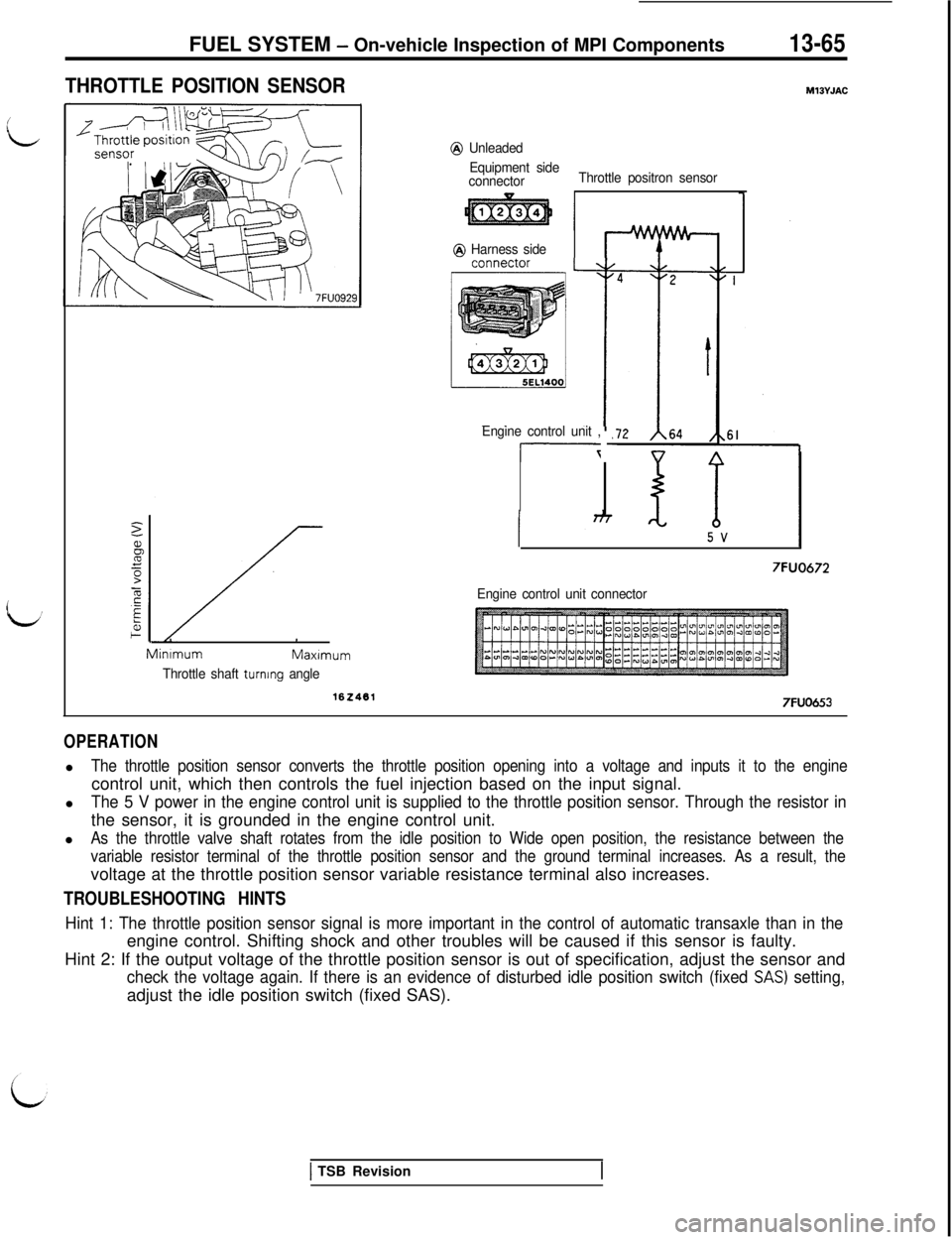
OPERATIONl
The throttle position sensor converts the throttle position opening into a voltage and inputs it to the enginecontrol unit, which then controls the fuel injection based on the input signal.
l
The 5 V power in the engine control unit is supplied to the throttle position sensor. Through the resistor inthe sensor, it is grounded in the engine control unit.
l
As the throttle valve shaft rotates from the idle position to Wide open position, the resistance between the
variable resistor terminal of the throttle position sensor and the ground terminal increases. As a result, thevoltage at the throttle position sensor variable resistance terminal also increases.
TROUBLESHOOTING HINTS
Hint 1: The throttle position sensor signal is more important in the control of automatic transaxle than in theengine control. Shifting shock and other troubles will be caused if this sensor is faulty.
Hint 2: If the output voltage of the throttle position sensor is out of specification, adjust the sensor and
check the voltage again. If there is an evidence of disturbed idle position switch (fixed SAS) setting,adjust the idle position switch (fixed SAS).
1 TSB Revision
Page 172 of 1146
13-66FUEL SYSTEM - 0n-vehicle Inspection of MPI Components
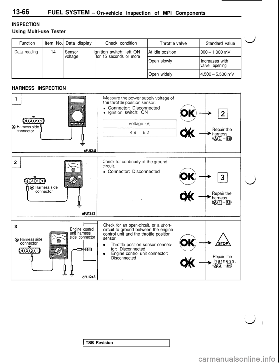
INSPECTIONUsing Multi-use Tester
FunctionItem No. Data displayCheck conditionThrottle valveStandard value‘d
Data reading14SensorIgnition switch: left ONvoltagefor 15 seconds or moreAt idle position300-1.000 mV
Open slowly
Increases withvalve opening
Open widely4.500-5.500 mV
HARNESS INSPECTIONl Connector: Disconnected
l
lgnrtion switch: ON
l Connector: Disconnected
connector
I
Engine controlCheck for an open-circuit, or a short-
unit harnesscircuit to ground between the engine
side connectorcontrol unit and the throttle positionsensor.
Throttle position sensor connec-
tor: Disconnected
Engine control unit connector:
DisconnectedRepair theB-3 harness.
km-8)
-z =6FU1243
[ TSB Revision
Page 173 of 1146
FUEL SYSTEM - On-vehicle Inspection of MPI Components13-67
(sensor side, front view7FU048t7FUO67:
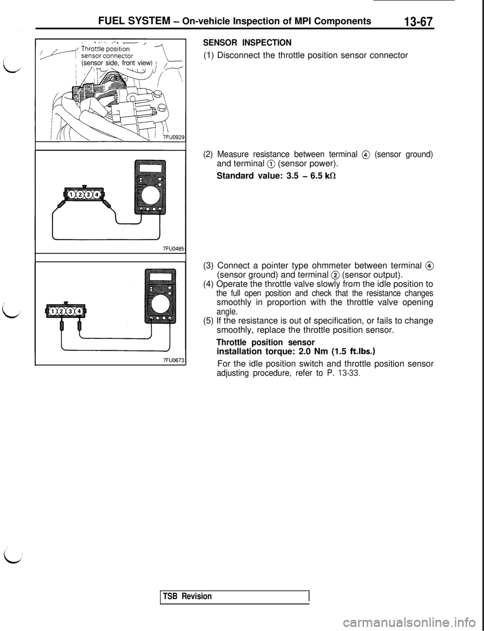
SENSOR INSPECTION(1) Disconnect the throttle position sensor connector
(2) Measure resistance between terminal @ (sensor ground)and terminal
@ (sensor power).
Standard value: 3.5
- 6.5 kR(3) Connect a pointer type ohmmeter between terminal
@(sensor ground) and terminal
@ (sensor output).
(4) Operate the throttle valve slowly from the idle position to
the full open position and check that the resistance changessmoothly in proportion with the throttle valve opening
angle.(5) If the resistance is out of specification, or fails to change
smoothly, replace the throttle position sensor.
Throttle position sensorinstallation torque: 2.0 Nm (1.5
ft.lbs.)For the idle position switch and throttle position sensor
adjusting procedure, refer to P. 13-33.
TSB Revision1
Page 174 of 1146
13-68FUEL SYSTEM - On-vehicle Inspection of MPI Components
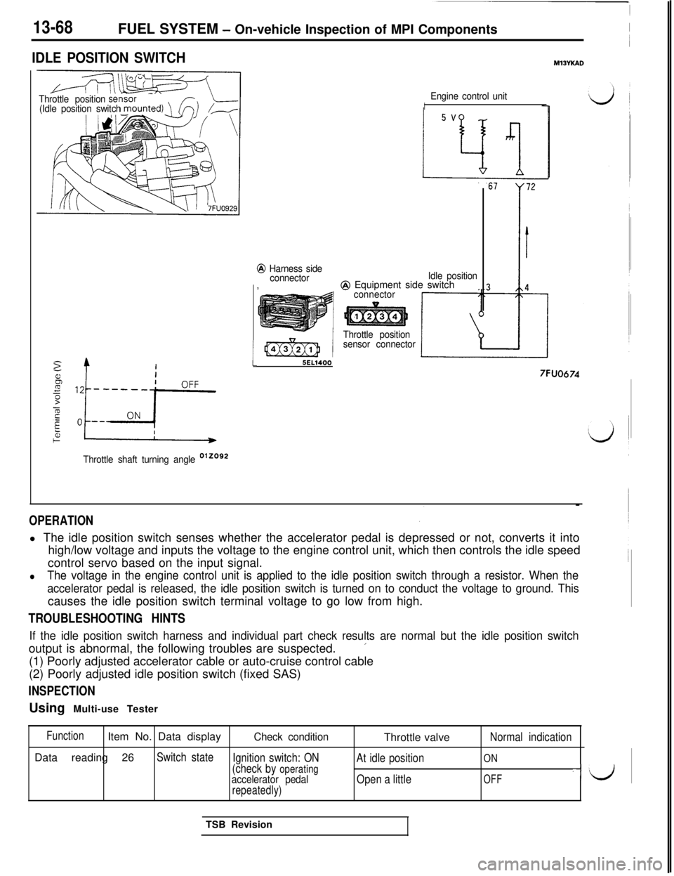
IDLE POSITION SWITCHMlBYKAD
Throttle positionse(Idle position switch
2
/bz----;-p
b+i
Throttle shaft turning angle D’20g2
i
Engine control unitI
@ Harness side
connectorIdle position,
@ Equipment side switchconnector
Throttle position
sensor connector
5EL1400
7FUO674
OPERATIONl The idle position switch senses whether the accelerator pedal is depressed or not, converts it into
high/low voltage and inputs the voltage to the engine control unit, which then controls the idle speed
control servo based on the input signal.
lThe voltage in the engine control unit is applied to the idle position switch through a resistor. When the
accelerator pedal is released, the idle position switch is turned on to conduct the voltage to ground. Thiscauses the idle position switch terminal voltage to go low from high.
TROUBLESHOOTING HINTS
If the idle position switch harness and individual part check results are normal but the idle position switchoutput is abnormal, the following troubles are suspected.
’(1) Poorly adjusted accelerator cable or auto-cruise control cable
(2) Poorly adjusted idle position switch (fixed SAS)
INSPECTIONUsing Multi-use Tester
FunctionItem No. Data displayCheck conditionThrottle valveNormal indicationData reading 26
Switch state
Ignition switch: ONON(check by operatingAt idle position
accelerator pedalOpen a littleOFF-J
repeatedly)TSB Revision
Page 175 of 1146
FUEL SYSTEM - On-vehicle InsDection of MPI ComDonents13-69
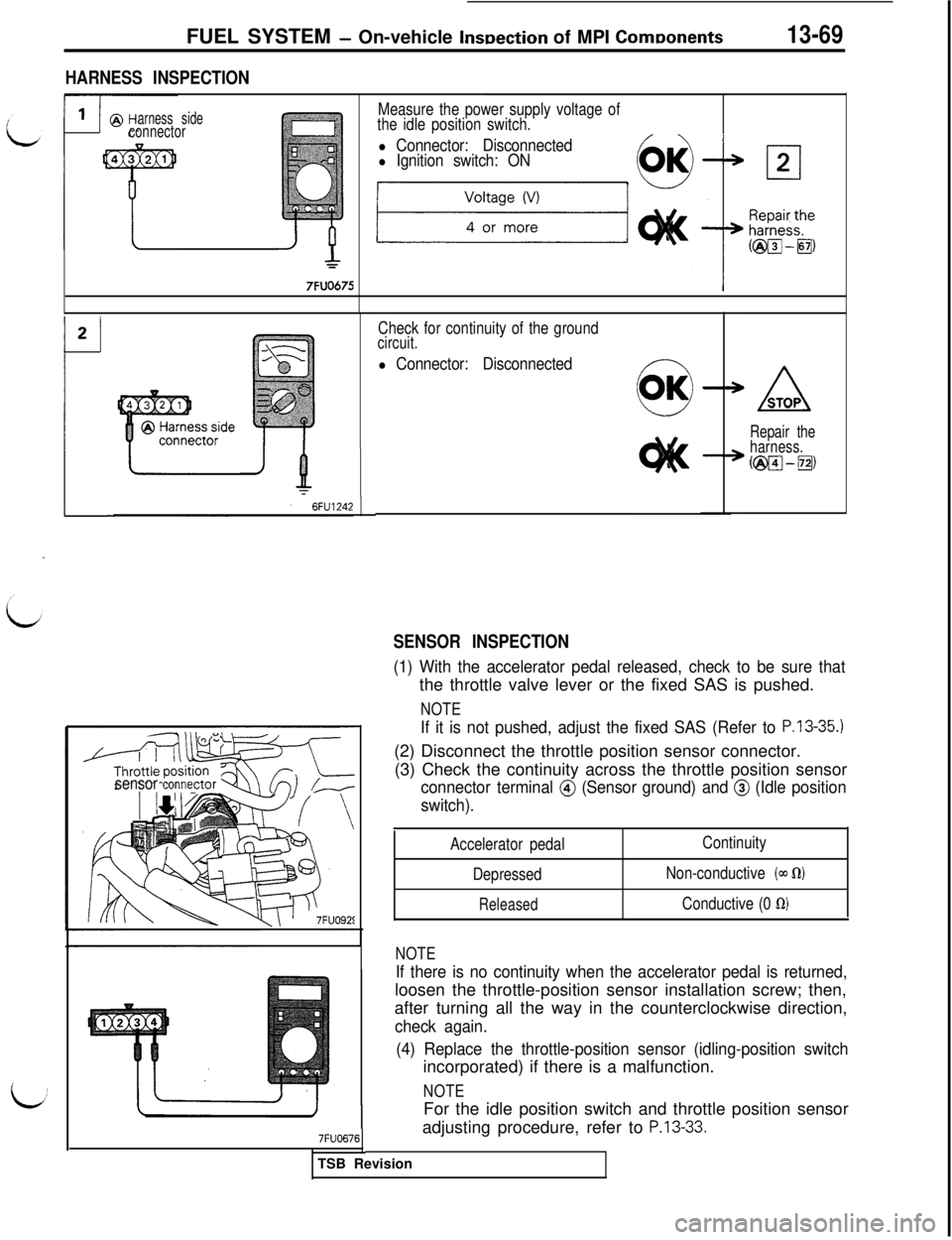
HARNESS INSPECTION
arness sideconnector
7FUO675
Measure the power supply voltage of
the idle position switch.
l Connector: Disconnectedl Ignition switch: ON
Check for continuity of the groundcircuit.
l Connector: Disconnected
SENSOR INSPECTION
sensor tonne
ASTOP
Repair the
harness.
@w--~)
(1) With the accelerator pedal released, check to be sure thatthe throttle valve lever or the fixed SAS is pushed.
NOTE
If it is not pushed, adjust the fixed SAS (Refer to P.13-35.)(2) Disconnect the throttle position sensor connector.
(3) Check the continuity across the throttle position sensor
connector terminal @ (Sensor ground) and @ (Idle position
switch).
Accelerator pedal
Depressed
Released
Continuity
Non-conductive
(a~ KU
Conductive (0 fi)
7FUO676
NOTE
If there is no continuity when the accelerator pedal is returned,loosen the throttle-position sensor installation screw; then,
after turning all the way in the counterclockwise direction,
check again.
(4) Replace the throttle-position sensor (idling-position switchincorporated) if there is a malfunction.
NOTEFor the idle position switch and throttle position sensor
adjusting procedure, refer to
P.13-33.TSB Revision
Page 176 of 1146
FUEL SYSTEM - 0n-vehicleInspection of MPI Components
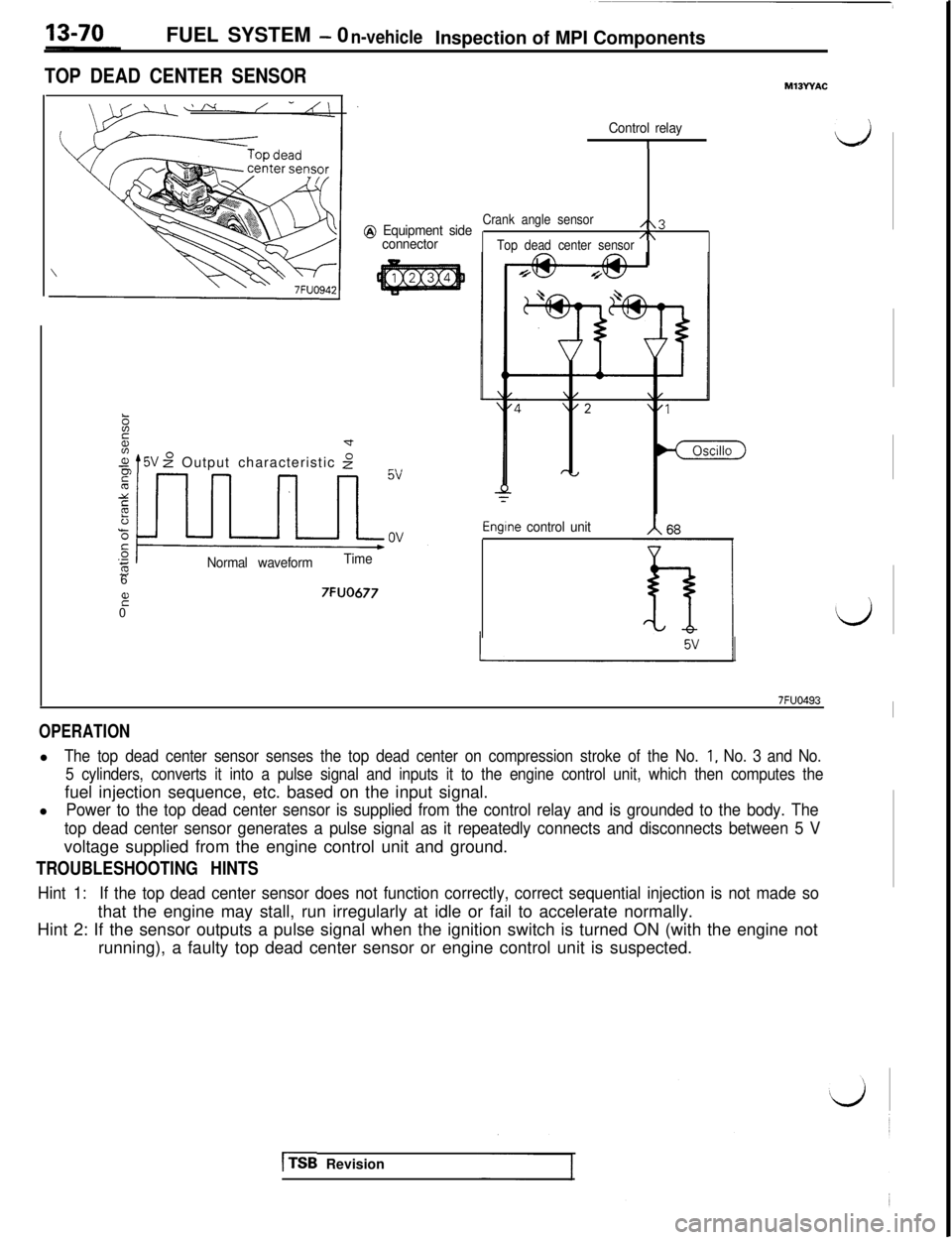
TOP DEAD CENTER SENSOR
Control relay
1d
@ Equipment side
connector
zd
.+$ t5V z” Output characteristic 2r~,
Normal waveformTime6
it07FUO677
Crank angle sensor/\3
Top dead center sensor/\
Engtne control unit
d
7FUO493I
OPERATIONl
The top dead center sensor senses the top dead center on compression stroke of the No. 1, No. 3 and No.
5 cylinders, converts it into a pulse signal and inputs it to the engine control unit, which then computes thefuel injection sequence, etc. based on the input signal.
l
Power to the top dead center sensor is supplied from the control relay and is grounded to the body. The
top dead center sensor generates a pulse signal as it repeatedly connects and disconnects between 5 Vvoltage supplied from the engine control unit and ground.
TROUBLESHOOTING HINTS
Hint 1:If the top dead center sensor does not function correctly, correct sequential injection is not made sothat the engine may stall, run irregularly at idle or fail to accelerate normally.
Hint 2: If the sensor outputs a pulse signal when the ignition switch is turned ON (with the engine not
running), a faulty top dead center sensor or engine control unit is suspected.
[TSB Revision
Page 178 of 1146
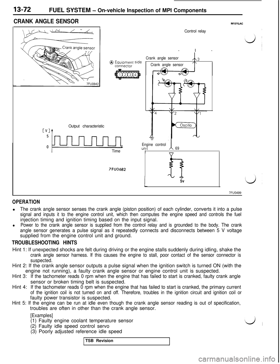
13-72FUEL SYSTEM - On-vehicle Inspection of MPI Components
CRANK ANGLE SENSOR
co.ntiector
Output characteristic
LTime
7FUO682
MllYiAC
Control relay-I-
Crank angle sensorsideA3
Crank angle sensor/\
‘=
Engine controlunft69I
1
h5v
7FUO499
OPERATIONl
The crank angle sensor senses the crank angle (piston position) of each cylinder, converts it into a pulse
signal and inputs it to the engine control unit, which then computes the engine speed and controls the fuelinjection timing and ignition timing based on the input signal.
lPower to the crank angle sensor is supplied from the control relay and is grounded to the body. The crank
angle sensor generates a pulse signal as it repeatedly connects and disconnects between 5 V voltagesupplied from the engine control unit and ground.
TROUBLESHOOTING HINTSHint 1: If unexpected shocks are felt during driving or the engine stalls suddenly during idling, shake the
crank angle sensor harness. If this causes the engine to stall, poor contact of the sensor connector is
suspected.Hint 2: If the crank angle sensor outputs a pulse signal when the ignition switch is turned ON (with the
engine not running), a faulty crank angle sensor or engine control unit is suspected.
Hint 3:
If the tachometer reads 0 rpm when the engine that has failed to start is cranked, faulty crank angleHint 4:sensor or broken timing belt is suspected.
If the tachometer reads 0 rpm when the engine that has failed to start is cranked, the primary current
of the ignition coil is not turned on and off. Therefore, troubles in the ignition circuit and ignition coil orfaulty power transistor is suspected.
Hint 5: If the engine can be run at idle even though the crank angle sensor reading is out of specification,troubles are often in other than the crank angle sensor.
[Examples](1) Faulty engine coolant temperature sensor
(2) Faulty idle speed control servo
(3) Poorly adjusted reference idle speed
TSB Revision
Page 184 of 1146
![MITSUBISHI 3000GT 1991 Workshop Manual 13-78FUEL SYSTEM - 0n-vehicleInspection of MPI Components
VEHICLE SPEED SENSORMIBYPM
Vehrcle speed sensor
(reed switch\)Speedometer
Terminal voltage
(V)
@ Equipment side
Vehicle speed [km/h (mph)]
16 MITSUBISHI 3000GT 1991 Workshop Manual 13-78FUEL SYSTEM - 0n-vehicleInspection of MPI Components
VEHICLE SPEED SENSORMIBYPM
Vehrcle speed sensor
(reed switch\)Speedometer
Terminal voltage
(V)
@ Equipment side
Vehicle speed [km/h (mph)]
16](/img/19/57085/w960_57085-183.png)
13-78FUEL SYSTEM - 0n-vehicleInspection of MPI Components
VEHICLE SPEED SENSORMIBYPM
Vehrcle speed sensor
(reed switch\)Speedometer
Terminal voltage
(V)
@ Equipment side
Vehicle speed [km/h (mph)]
162461
Engine control unit
7FUO925
Engine control unit connector7FUO653
OPERATION
lThe vehicle speed sensor which is located in the speedometer converts the vehicle speed into a pulse
signal and inputs it to the engine control unit, which then provides the idle speed control, etc. based on
this signal.
lThe vehicle speed sensor generates the vehicle speed signal by repeatedly opening and closing betweenthe voltage of about 5 V applied from the engine control unit and ground using a reed switch.
TROUBLESHOOTING HINTS
If there is an open or short circuit in the vehicle speed sensor signal circuit, the engine may stall when thevehicle is decelerated to stop.
HARNESS INSPECTION
unit harness
side connectorCheck the vehicle speed sensor out-
put circuit for continuity.
lEngine control unit connector:
Disconnected
lMove the vehicle.
TSB Revision
1
d