Ignition MITSUBISHI 3000GT 1994 2.G Workshop Manual
[x] Cancel search | Manufacturer: MITSUBISHI, Model Year: 1994, Model line: 3000GT, Model: MITSUBISHI 3000GT 1994 2.GPages: 738, PDF Size: 35.06 MB
Page 617 of 738
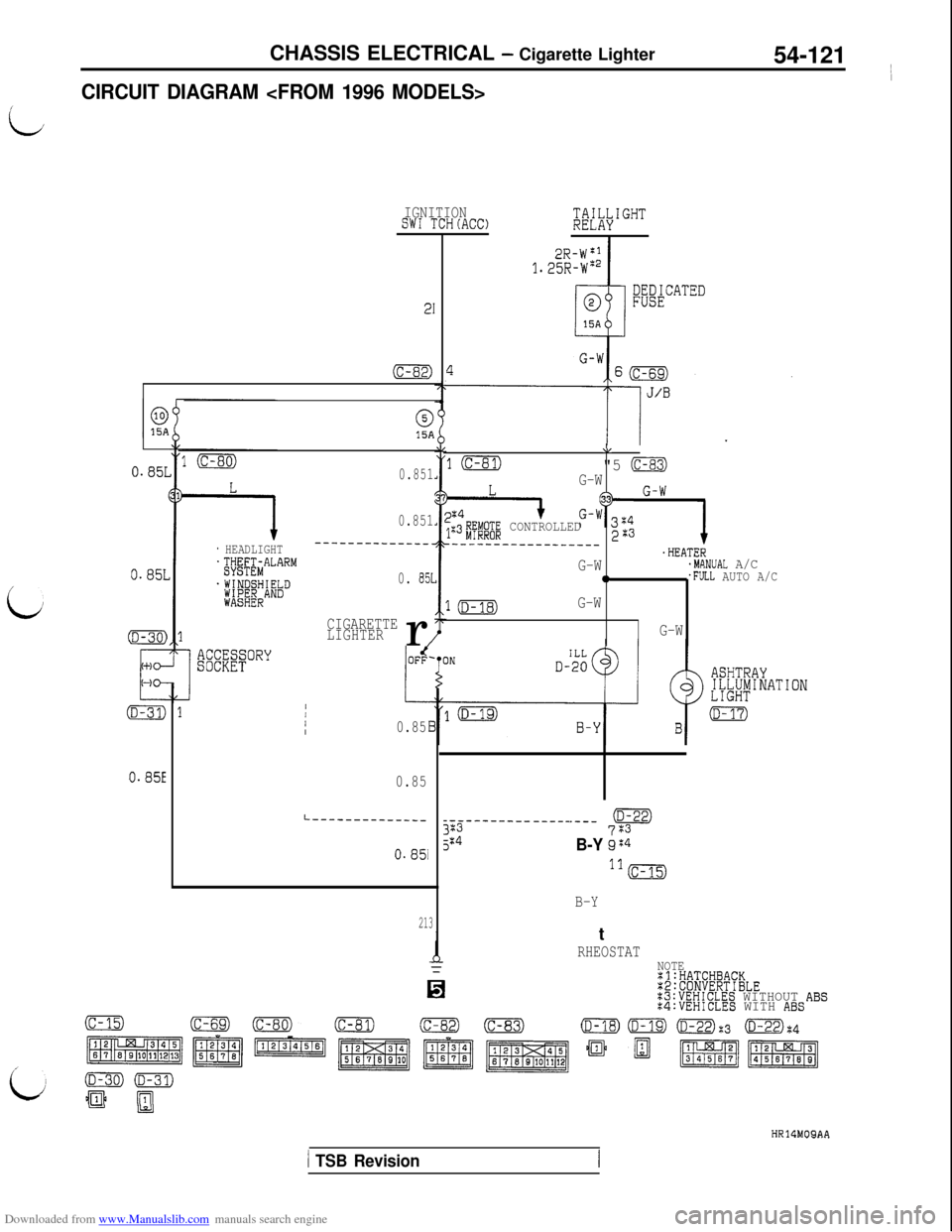
Downloaded from www.Manualslib.com manuals search engine CHASSIS ELECTRICAL - Cigarette Lighter
54-121 ~
I
CIRCUIT DIAGRAM
L
IGNITIONSW1 TCH(AC0;&I""'
I
;&$CATED
21
(c-82)
015A
0.851
0.851
_______--____-_
0. 851
CIGARETTE
LIGHTERr
/
\I
10"5 (c-83)G-W
I+G-?3z4 G-W;:3#E;"@ CONTROLLED223--__--___----______.HEATERG-W.MANUAL A/C0.FULL AUTO A/C
1mG-W
G-W
0.85L
/
0.85L
* HEADLIGHT~~~~;&A""""
.WINDSHIELD;ft;;ERAND
L
1/III0.85
0.85
.---pt+
B-Y gG4ll(c-15)
B-Y
L------------------------- -----3235:40.85i
213IRHEOSTATNOTE:l:HATCHBACK:2:CONVERTIBLE:3:VEHICLES WITHOUT ABS:4:VEHICLES WITH ABS
(c-15)(c-82)(D-22):3 (D-22):4
p$$g'Tqgq,
ii
HR14MOQAA
1 TSB Revision
Page 624 of 738
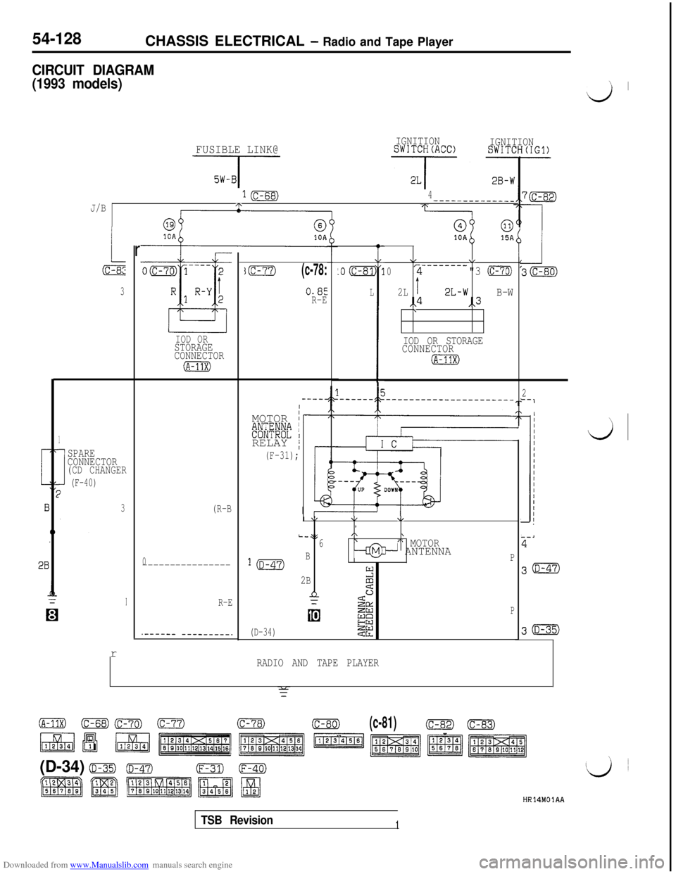
Downloaded from www.Manualslib.com manuals search engine 54-128CHASSIS ELECTRICAL - Radio and Tape Player
CIRCUIT DIAGRAM
(1993 models)
’ I
d
FUSIBLE LINK@
J-
IGNITIONSWITCH(ACC)IGNITIONSWITCH(IG1)
1B4------------__J/B/T\
r
3
1
I
SPARE
CONNECTOR
(CD CHANGER
(F-40)I
3r
IOD ORSTORAGE
CONNECTOR
(A-11x)
(R-B
0----------------
R-E
.------ ---------.
jm(c-78:
0.85
R-E
IMOTOR
I#$@E;'ti IRELAY
/
(F-31);
L
.o (c-81
L
I
11
I
\/V-------_02"3 CmTg
2LI2L-wB-W,,4,,3\
IOD OR STORAGE
CONNECTOR
IA-11X)I
\/\/\I,
L-;(,\\6\A MOTOR
l(D-47)B--@3- ANTENNAP
2B2
n3SaL
EEP
(D-34)22
RADIO AND TAPE PLAYER
f
2‘-1
30
30
d
(A-1Ix) (c-ss)Crn) (c-77)(c-78)(c-80)(c-81)(c-82)-
\
(D-34) o(D-47)(F-31)0
HR14MOlAA
TSB Revision1
Page 628 of 738
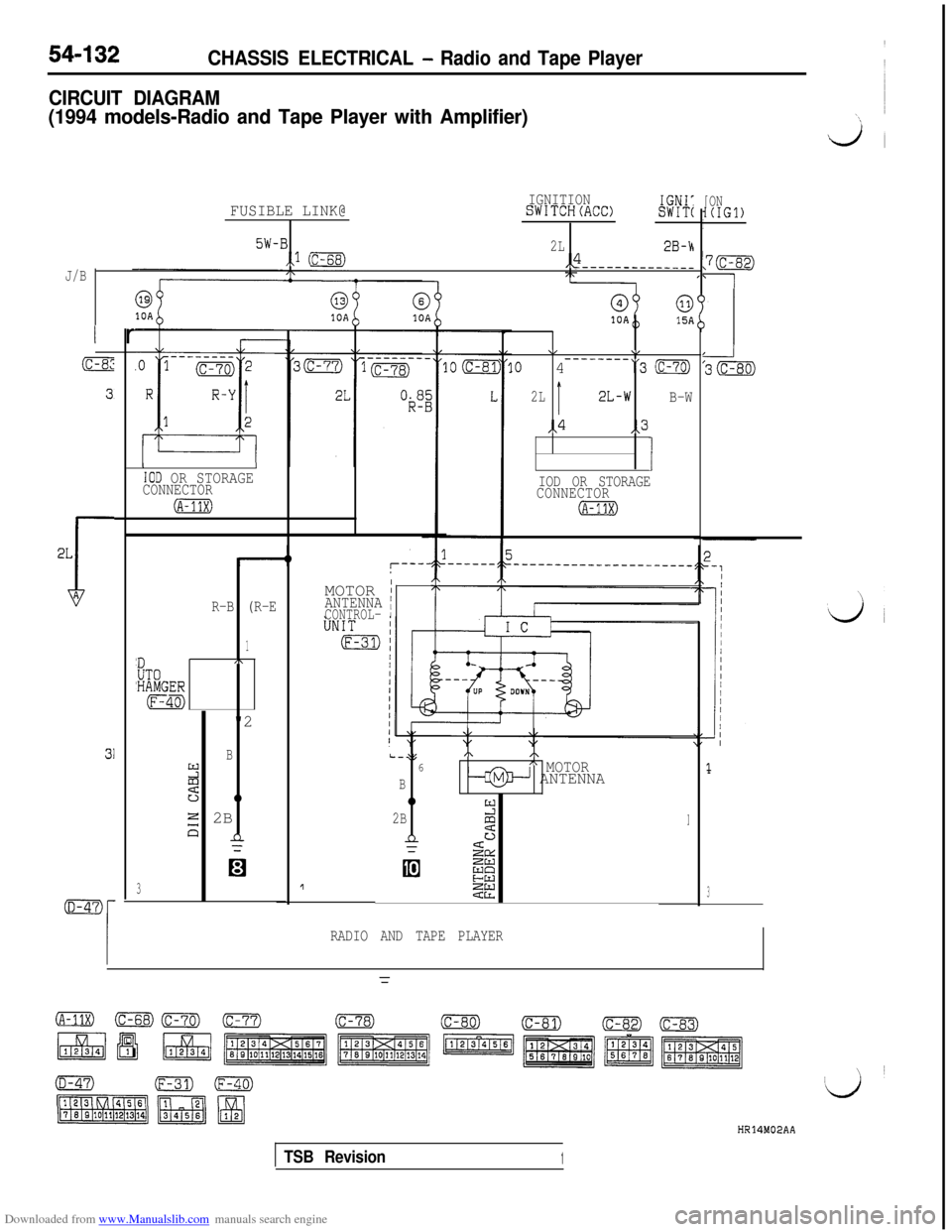
Downloaded from www.Manualslib.com manuals search engine 54-132CHASSIS ELECTRICAL - Radio and Tape Player
CIRCUIT DIAGRAM
(1994 models-Radio and Tape Player with Amplifier)
FUSIBLE LINK@IGNITIONSWITCH(ACC)IGNI:SWIT(
5W-B2L,.1 (c-68)2B-h,4
J/B----------____
I rI
IIOD OR STORAGECONNECTOR
(A-11x)
R-B (R-E
1
'DA
UT0'HAMGER
(F-40)
"2
B2z
0
E 2B13n
3
I
\/v--------.o 4“3 (c-70)
2LI2L-w
B-W
,,4,,3
1IOD OR STORAGE
CONNECTOR
(A-13X)MOTOR
IANTENNA jCONTROL- I
L-35/\,\6fi MOTOR
B-+@+ ANTENNA
0
2Btr:z1
n&
GE
!2g
[ON1(IGl)I
3
RADIO AND TAPE PLAYER
HR14M02AA
TSB Revision1
Page 632 of 738
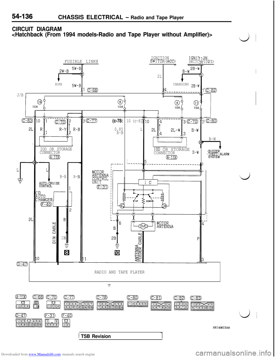
Downloaded from www.Manualslib.com manuals search engine 54-136CHASSIS ELECTRICAL - Radio and Tape Player
CIRCUIT DIAGRAM
d
I
FUSIBLE LINK@IGNITIONSWITCH(ACC)IGNIlSWITC
2W-B
1
B-W2B-w
2LIHORN5W-B
,,l (c-68)
CHARGING 2B-W
,,4------___----_cl\I
IN(IGl)
‘(c-82,
I
i(c-80)
J/B
@10A
tII
IOD OR STORAGE B-WCONNECTOR
(A-11X)
IIIOD OR STORAGE
CONNECTOR
(A-11X)
L
1R-B
W4igfUISE
ID,UTO:HAMGERr
3m(c-78:
0.85
R-B
10 (c-81
L
1.------
B-W
.BUZZER.@;&ALARM
dR-E
2E
RADIO AND TAPE PLAYER
HR14M03AA
1 TSB Revision
Page 636 of 738
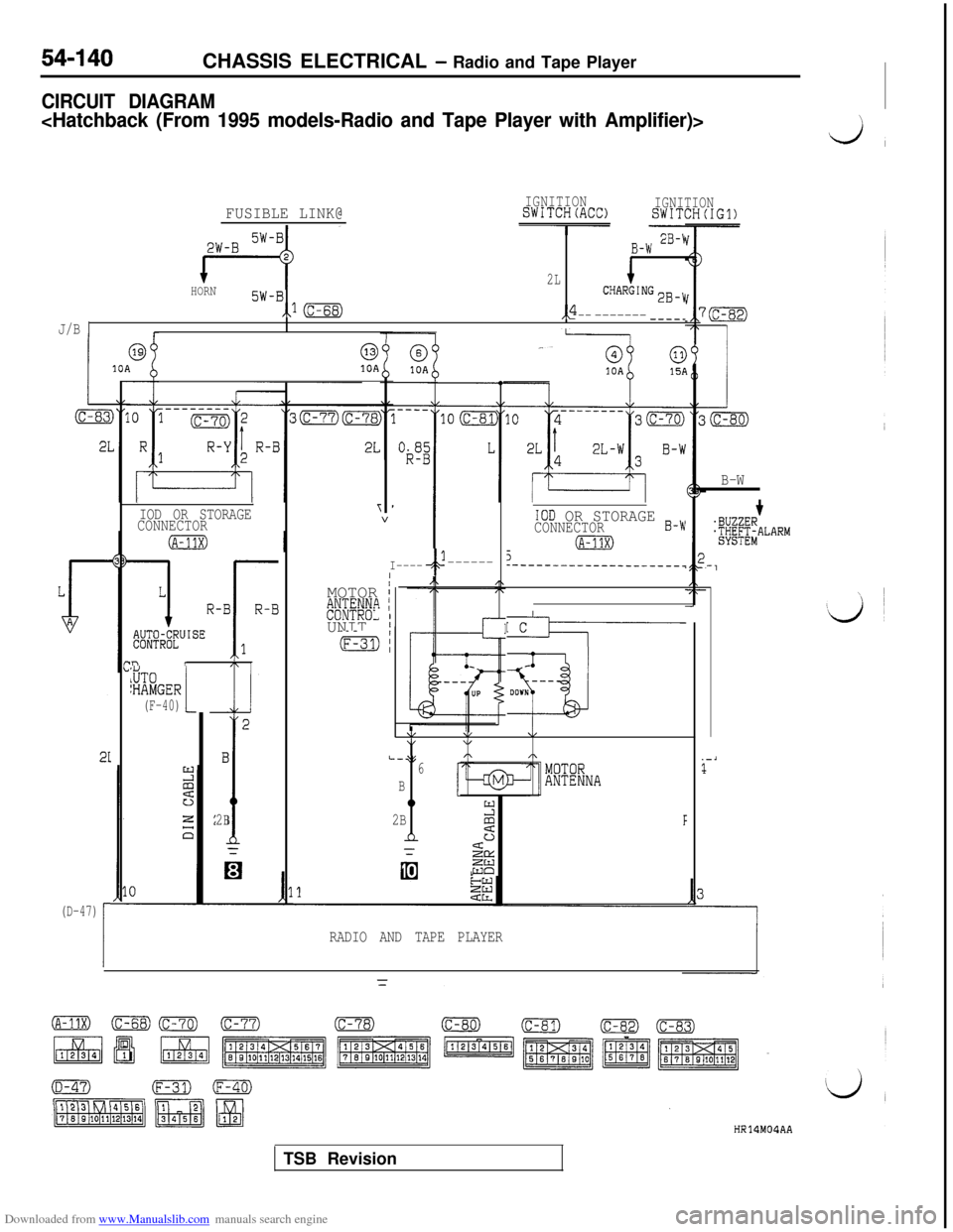
Downloaded from www.Manualslib.com manuals search engine 54-140CHASSIS ELECTRICAL - Radio and Tape Player
CIRCUIT DIAGRAM
J,
IGNITIONSWITCH(ACC)IGNITIONSWITCH(IG1)FUSIBLE LINK@
B-W 2B-\i
2L1HORN5W-BCHARGING2B-y
,,I(c-68),4--J/B1-----------_
I1
010A
T
1I----4------I
MOTOR
I#&#L" IUNIT
I
(F-31):
(D-47)
1
B-W
IIIOD OR STORAGE
CONNECTOR+'BUZZERTW&ALARMIOD OR STORAGE B-wCONNECTOR
5(A-11X)I----__-------__-------
-1
rc
---
v
DOW'tT0jHAMGER(F-40)!
2B
*\/4,4,\,L-35,\,\6
B
0
2BY
2F
n
ii&
Ei
_-i2
RADIO AND TAPE PLAYER
HR14M04AATSB Revision
Page 640 of 738
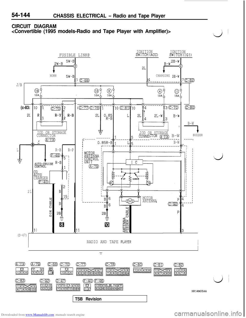
Downloaded from www.Manualslib.com manuals search engine 54-144CHASSIS ELECTRICAL - Radio and Tape Player
CIRCUIT DIAGRAM
d’
FUSIBLE LINK@IGNITIONSWITCH(ACC)IGNITIONSWITCH(IG1)
p&J-B SW-i
1
22L
HORN5W-BCHARGING 33-W
,,I (c-68),$-----------___,,7(c-82)
J/BI\
@10A
(c-83:
21
L
$A
2
‘1--------01 (c-70)2
i
RR-Yt1R-B2
L------__l-2y3(c-70)
_J
(c-80)
IIIOD OR STORAGE
CONNECTOR,
0L
1
R-B
R-P
my,
;;;4i;eUISE R-B1,,l I
:ZiTO
I,\ ,I
CHAMGERI
(F-40) '
L
*l-(D-47)
i
r.l
E
;
2ec
0
I
IOD OR STORAGE:TOR (~-11~) B-W--------_--___
B-WB-W
7BUZZER
----1r------------IIIF-:
MOTORi----_-_---ANTENNA
RADIO AND TAPE PLAYERI
d
HR14MOSAA
TSB Revision
Page 644 of 738
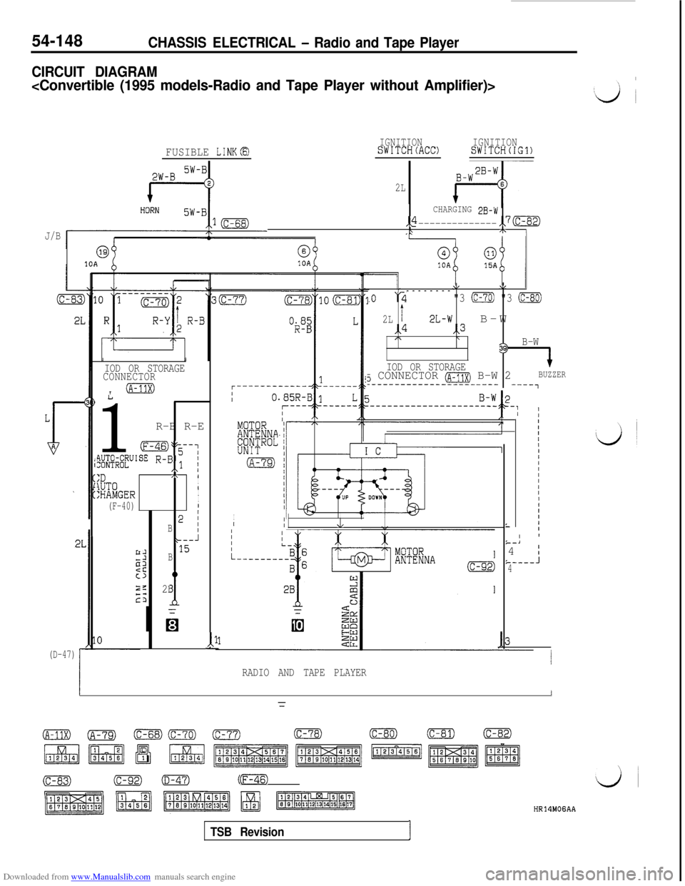
Downloaded from www.Manualslib.com manuals search engine 54-148CHASSIS ELECTRICAL - Radio and Tape Player
CIRCUIT DIAGRAM
J/B
FUSIBLE LINKB
69@10A10A
(D-47)
III
IOD OR STORAGE
CONNECTOR
T@m
1
R-B R-E
oy-;
flW&UISE R-B,,l i
:D,\ 1
lUT0I
:HAMGER/I
(F-40)II
B2 i
* J
:15B
z
c
z2B
d
2L
CHARGING 2B-w
,,4--------------,,7(c-82)\+ I
11-
IGNITIONSWITCH(ACC)IGNITIONSWITCH(IG1)
\/\/--------
.o ‘2"3 (c-70) "3 (c-80)
2Lt2L-wB-W,,4,,3/\\39)B-W
IOD OR STORAGE
+
3 CONNECTOR (A-11X) B-W 2BUZZER_---------------------- ----,
I
,IIIIII,II/IIIIIIIIIL
RADIO AND TAPE PLAYER
L
IIIIII/IIIIIIIII1IIIII ’k--J4 I&-----J4
I
=
o(A-79)(c-68)Gm) (c-77)(c-78)(c-80)(c-81)(c-82)
(c-83)(C-92)0mm)(F-46)
TSB RevisionI
HR14MOGAA
Page 660 of 738
Downloaded from www.Manualslib.com manuals search engine 54-164CHASSIS ELECTRICAL - Radio and Tape Player
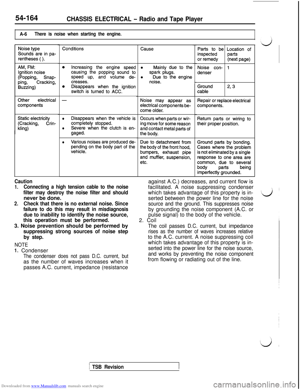
A-6There is noise when starting the engine.
Noise type
Sounds are in pa-
rentheses ( ).
AM, FM:
Ignition noise
(Popping, Snap-
ping,Cracking,
Buzzing)
Otherelectrical
components
Static electricity
(Cracking, Crin-
kling)
Conditions
0Increasing the engine speedcausing the popping sound tospeed up, and volume de-creases.0Disappears when the ignitionswitch is turned to ACC.
-
lDisappears when the vehicle is
completely stopped.Occurs when parts or wir-
Severe when the clutch is en-ing move for some reasonlgaged.and contact metal parts of
the body.
lVarious noises are produced de-pending on the body part of thevehicle.
Due to detachment from
the body of the front hood,
bumpers, exhaust pipe
and muffler, suspension,
etc.
Causel
Mainly due to the
spark plugs.l Due to the enginenoise.
Noise may appear as
electrical components be-
come older.
Parts to be Location of
inspectedparts
or remedy(next page)
Noise con- 1
denser
Ground
cable2, 3
Repair or replace electricalcomponents.
Return parts or wiring to
their proper position.
Caution
1.Connecting a high tension cable to the noise
filter may destroy the noise filter and shouldnever be done.
2.Check that there is no external noise. Since
failure to do this may result in misdiagnosis
due to inability to identify the noise source,
this operation must be performed.3. Noise prevention should be performed by
suppressing strong sources of noise step
by step.
NOTE
1. Condenser
The condenser does not pass D.C. current, butas the number of waves increases when it
passes A.C. current, impedance (resistanceagainst A.C.) decreases, and current flow is
facilitated. A noise suppressing condenser
which takes advantage of this property is in-
serted between the power line for the noise
source and the ground. This suppresses noiseby grounding the noise component (A.C. or
pulse signal) to the body of the vehicle.
2. Coil
The coil passes D.C. current, but impedance
rises as the number of waves increases relativeto the A.C. current. A noise suppressing coil
which takes advantage of this property is in-
serted into the power line for the noise source,
and works by preventing the noise componentfrom flowing or radiating out of the line.
1 TSB Revision
Ground parts by bonding.
Cases where the problem
is not eliminated by a single
response to one area are
common, due to several
bodypartsbeing
imperfectly grounded.
Page 676 of 738
Downloaded from www.Manualslib.com manuals search engine CHASSIS ELECTRICAL - Radio and Taste Plaver
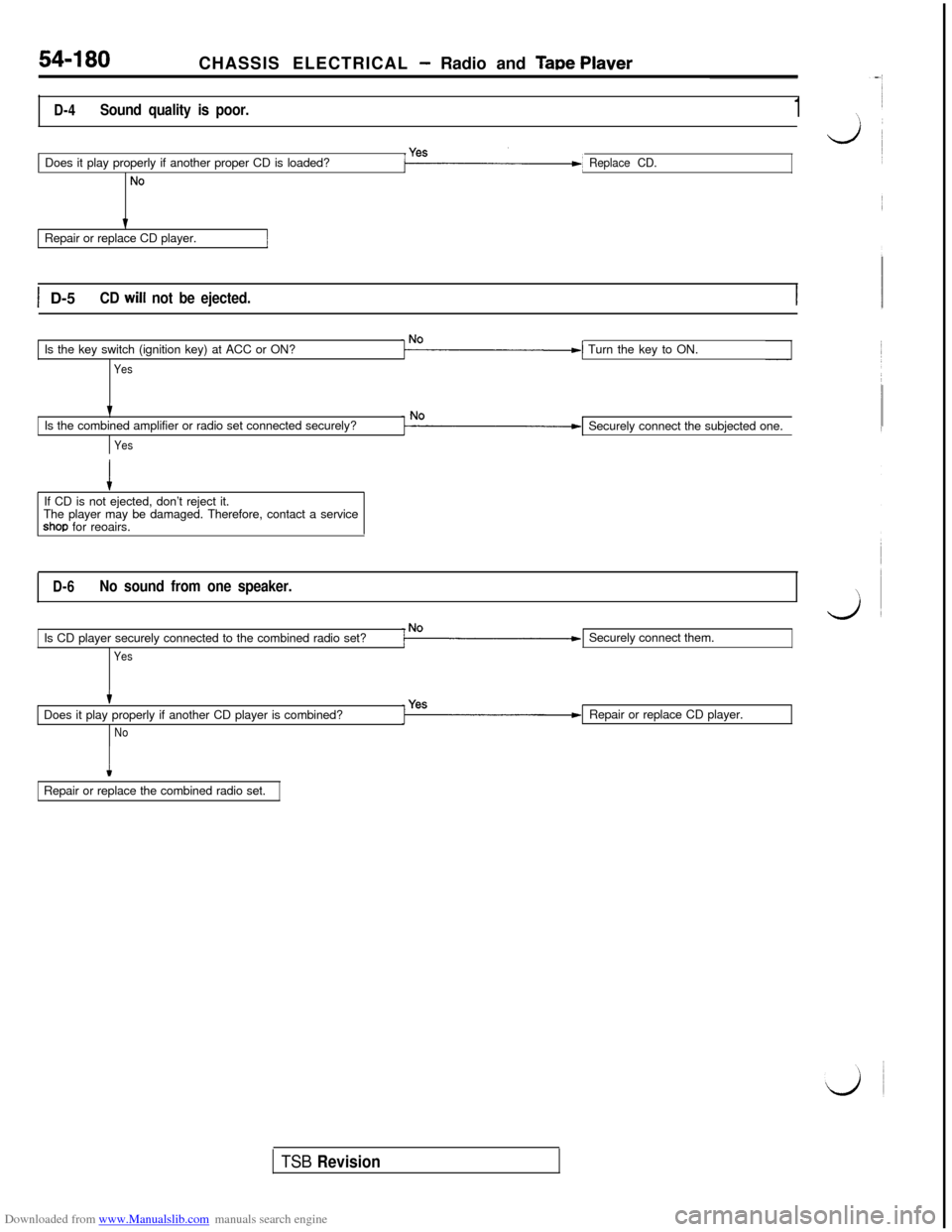
D-4Sound quality is poor.1Does it play properly if another proper CD is loaded?
No
Replace CD.Repair or replace CD player.
1 D-5CD will not be ejected.Is the key switch (ignition key) at ACC or ON?
YesTurn the key to ON.
tIs the combined amplifier or radio set connected securely?
YesSecurely connect the subjected one.
If CD is not ejected, don’t reject it.
The player may be damaged. Therefore, contact a service
shop for reoairs.
D-6No sound from one speaker.Is CD player securely connected to the combined radio set?
YesSecurely connect them.
Does it play properly if another CD player is combined?
NoRepair or replace CD player.
IRepair or replace the combined radio set.
TSB Revision
Page 680 of 738
Downloaded from www.Manualslib.com manuals search engine 54-184CHASSIS ELECTRICAL - Radio and Tape Plaver
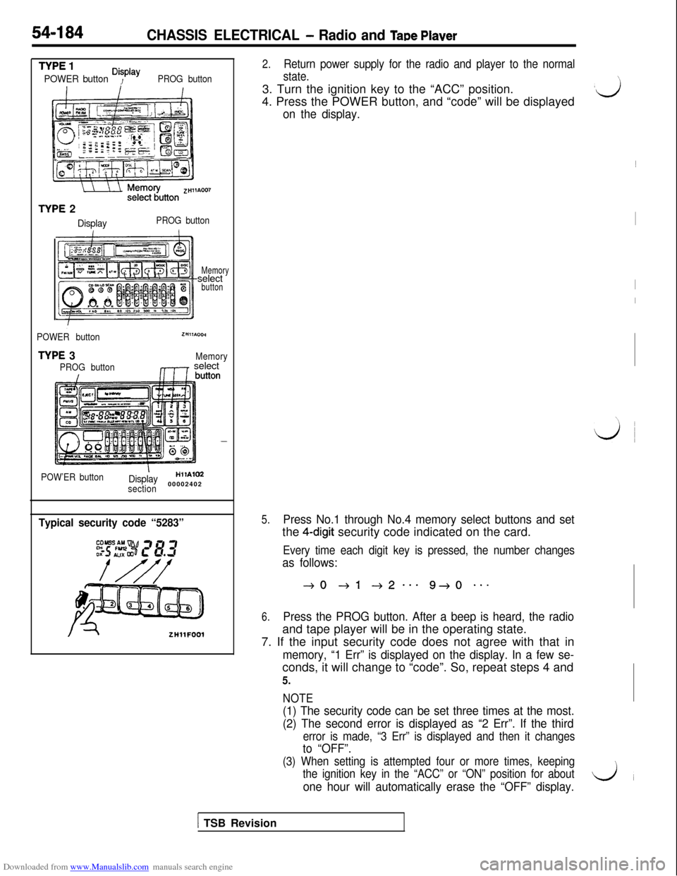
TYPE 1
POWER button Disp’ayPROG button
TYPE 2
DisplayPROG button
Memoryselect
button
POWER button
TYPE 3
PROG button
ZHllA004
Memory,1r select
POW’ER buttonIDisplayH’llAlM
section00002402
Typical security code “5283”
ZHllFOOl
2.Return power supply for the radio and player to the normal
state.3. Turn the ignition key to the “ACC” position.
4. Press the POWER button, and “code” will be displayed
on the display.
5.Press No.1 through No.4 memory select buttons and setthe
4-digit security code indicated on the card.
Every time each digit key is pressed, the number changes
as follows:
40 +l +2--e 9+0 **-
6.Press the PROG button. After a beep is heard, the radioand tape player will be in the operating state.
7. If the input security code does not agree with that in
memory, “1 Err” is displayed on the display. In a few se-conds, it will change to “code”. So, repeat steps 4 and
5.
NOTE
(1) The security code can be set three times at the most.
(2) The second error is displayed as “2 Err”. If the third
error is made, “3 Err” is displayed and then it changes
to “OFF”.
(3) When setting is attempted four or more times, keeping
the ignition key in the “ACC” or “ON” position for about
one hour will automatically erase the “OFF” display.
\
,ij~
I
I
I
\,
LJ
1 TSB Revision