Ignition MITSUBISHI 3000GT 1994 2.G Workshop Manual
[x] Cancel search | Manufacturer: MITSUBISHI, Model Year: 1994, Model line: 3000GT, Model: MITSUBISHI 3000GT 1994 2.GPages: 738, PDF Size: 35.06 MB
Page 564 of 738
Downloaded from www.Manualslib.com manuals search engine 54-68CHASSIS ELECTRICAL - Lighting System
CIRCUIT DIAGRAM
FUSIBLE:LINK@
2R-B
f=-.HEADLIGHT.FOG LIGHT
5/
1.25R-B
R-B
5
'4
1.25R-W
G-Y
AG-Y
6G-Y
IGNITIONSWITCH(IG1)
I2B-WB-W6
CHARGING2B-W,,7 (c-82)rm
q----J12
FUSIBLE LINK@
0
(c-02),,
4:
0
6
I\/
O“16(c-83:
.85B-W(F>R-
@0.85B-W
R-
.85B-W,8E%ffTUP
10A
IP II
(F>R-B
DOOR LIGHT AND
LUGGAGE COMPARTMENT
3 LIGHT
LIGHT
AUTOMATIC
SHUT-OFF
UNIT
(E-17)
(F>'
DOOR LIGHT ANDkY;k+GE COMPARTMENT
(F>Y 7
it
yE[F SWITCH
1 TSB Revision
Page 566 of 738
Downloaded from www.Manualslib.com manuals search engine 54-70CHASSIS ELECTRICAL - Lighting System
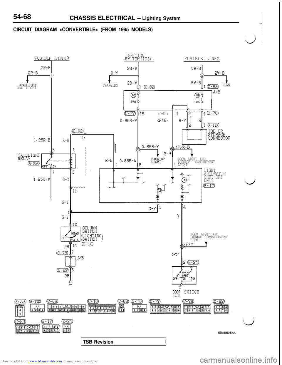
OPERATION
0When the lighting switch is placed in the TAILor HEAD position, current flows through the
coil of the tail light relay to the lighting switchand ground, causing the contacts of the tail
light relay to close.
Then current flows through the contacts of thetail light relay to the dedicated fuse
(2) the
individual lights and ground, causing the tail
lights, parking/side marker lights and licenseplate lights to go ON.
lIf the driver’s door is opened after the ignition
switch is turned to “OFF” or the ignition switchis turned to “OFF” after the driver’s door is
opened when the tail lights are lit, the current
which flows to the coil side of the tail light relaywill be cut off by the light automatic shut-off
unit opening the contact point, and the tail light
relay will be turned “OFF’ to automatically shut
off the tail lights, parking and front side marker
lights and license plate light.
lTo turn on the tail lights, parking and front side
marker lights and license plate light again after
they are automatically shut off, turn the lightingswitch to “OFF” once and to “HEAD” again,
or turn the ignition switch to “ACC” or “ON”,
and the automatic shut-OFF will be cancelled
and the current will flow from the light automaticshut-OFF unit to the coil side of the tail light
relay to close the contact point. Thus, the taillight relay will be turned “ON” to turn on the
tail lights, parking and front marker lights and
license plate light.
NOTE
When the lighting switch is at the “HEAD” position,
the light automatic shut-OFF system will be also
activated for the headlights. (Refer to P.54-37.) The
same system will also be activated for the illumina-
tion lights, etc.
TROUBLESHOOTING HINTS1. All lights don’t illuminate.
(1) The headlights don’t illuminate, either.l Check the fusible link (3).
(2) The headlights illuminate.l Check the tail light relay. (Refer to
P.54-108.)l Check the dedicated fuse (2).
l Check the lighting switch. (Refer to
P.54-113.)l Check the light automatic shut-OFF
unit. (Refer to
P.54-108.)2. Some light does not come on.
l Check the bulb.
l Check the grounding circuit.
3. Some light is not automatically shut off.
lCheck the driver’s side door switch.
(Refer to GROUP 42- Door Assembly.)l Check the automatic shut-OFF unit.
(Refer to
P.54-108.)
1 TSB Revision
Page 568 of 738
Downloaded from www.Manualslib.com manuals search engine 54-72CHASSIS ELECTRICAL - Lighting System
DOME LIGHT, FOOT LIGHT AND IGNITION KEY CYLINDER ILLUMINATION LIGHT
CIRCUIT DIAGRAM (UP TO
1993 MODELS)
FUSIBLE LINK@IGNITIONSWITCH(IGl)
5W-B,.l (c-68)2B-w,,7m/\\J/B
@0310A
L
(c-74)
R-B
I
IO"3 (c-80)
B-W
jl52;gF"___-_________ _----__--_-_--, IOD OR
STORAGE
CONNECTOR
(A-11X)
(c-83)
R-B
R-E
DOME
LIGHT
:E-05)(
R-G
I1(c-81)
0.85R-I
R-E
(LH) (RH:Z-67
-
R-c
$
KEY CYLINDERILLUMINATION
//
,
III
I
1IIIIIII
I
bIOOR
(c-74)
J/B r
(c-83))ICONNECTOR0------- -----
1
R-GIR-G2Ej
27
m(c-34)(c-58)(RH)(LH)\InY
DOOR SWITCH
d
R-G
R-G
d,HR08MlOAA
/ TSB Revision
Page 569 of 738
Downloaded from www.Manualslib.com manuals search engine CHASSIS ELECTRICAL - Lighting System
CIRCUIT DIAGRAM (1994 MODELS)54-73
IGNITIONSWITCH(IG1)IFUSIBLE L!NK@I5W-B2B-W
107m
1.
IOD OR STRAGE
CONNECTOR
(A-?1X)
15A (>
\I\/
‘1 (c-77)'3 (c-80)
B-W
51ETACS
__---_---------_____-_ !!1T--,52
(c-74:1
(F>R-B
R-B
1
ll(c-83) (c-81)
O.B5R-ER-I
>
R-B
R-B
c-35
) (<
FQO?LIGHTLH) (RH)'-67,
R-G
R-G
3>
!GNITION KEYCYLINDERILLUMINATION\gLIGHTEi(c-58)TIMERCIRCUIT6sec.
0
,iR-GR-B B B
,,4 (c-34)lE4 9 5
IA A * Al
R-G
R-GDATA LINK
CONNECTOR R-G
R-G
.NDV
AJj7:1jgZ2
(c-74
J/BR-G
NOTE:l:VEHICLES WI:2:VEHiCLES WITHOUT THEFT-ALARM SYSTEM
TH THEFT-ALARM SYSTEM
(RH)(LH)
DooR SWITCH
(c-77)OFRONT SIDE (C-80)(c-81)(c-82)AA
TSB Revision
Page 571 of 738
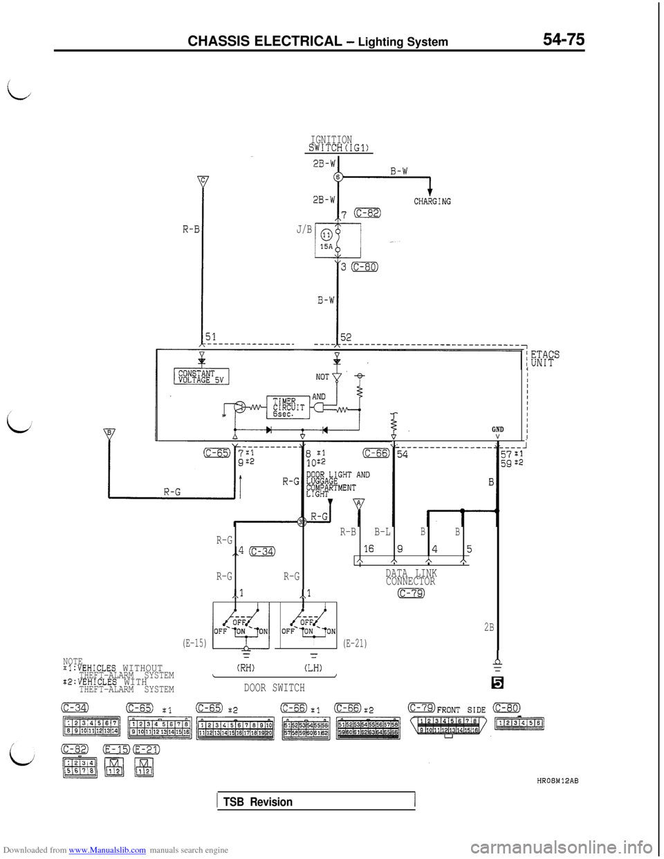
Downloaded from www.Manualslib.com manuals search engine CHASSIS ELECTRICAL - Lighting System54-75
IGNITIONSWITCH(IG1)
J/B
GNDV
. ,.
R-BB-LB
BR-G
,,4 (c-34116 945AAhA
R-GR-GDATA LINK
CONNECTOR
,,l,,l(c-79)
OFF--ON2B
(E-15)I(E-21)
NOTEYz
:l:VEHICLES WITHOUTTHEFT-ALARM SYSTEM(RH)(LH)\I%2:VEHICLES WITHTHEFT-ALARM SYSTEMDOOR SWITCH
A=
IIIIIIIIII1II
(c-34)(c-65) :Iic-65) ?;2(c-66):1 (C-66)$OFRONT sm 0
HROBMlPAB
1 TSB Revision
Page 572 of 738
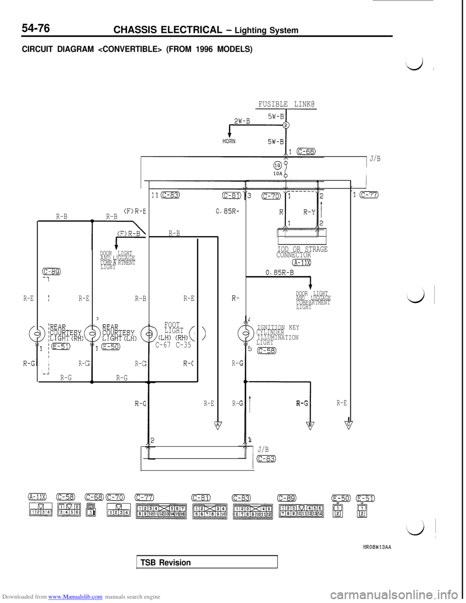
Downloaded from www.Manualslib.com manuals search engine 54-76CHASSIS ELECTRICAL - Lighting System
CIRCUIT DIAGRAM
FUSIBLE LINK@
J/B
R-E
R-BII
R-E
>
~REARICOURTESY I;LIGHT(RH:(
/pg
IIIR-C/'-iR-GR-B
(F)R-E
DOOR LIGHTAND UGGAGE!ACOMP RTMENT
LIGHT
R-B
1
>
[(E-50)
R-C
R-G
R-6
0.85R-
R-B
R-E
>
FOOT
LIGHT
(LH) (RH)(C-67 C-35
R-c
>
R-E
R-
(
R-
R-
>
IGNITION KEYCYLINDERILLUMINATION
LIGHT
l(c-58)
I
----I
R-G
B
I
J/B
(c-s3)
IOD OR STRAGE
CONNECTOR
(A-11XI
0.85R-B
DOOR LIGHT
AND LUGGAGE
COMPARTMENT
LIGHT
R-E
HROBMlSAA
TSB Revision
Page 574 of 738
Downloaded from www.Manualslib.com manuals search engine 54-78CHASSIS ELECTRICAL - Lighting System
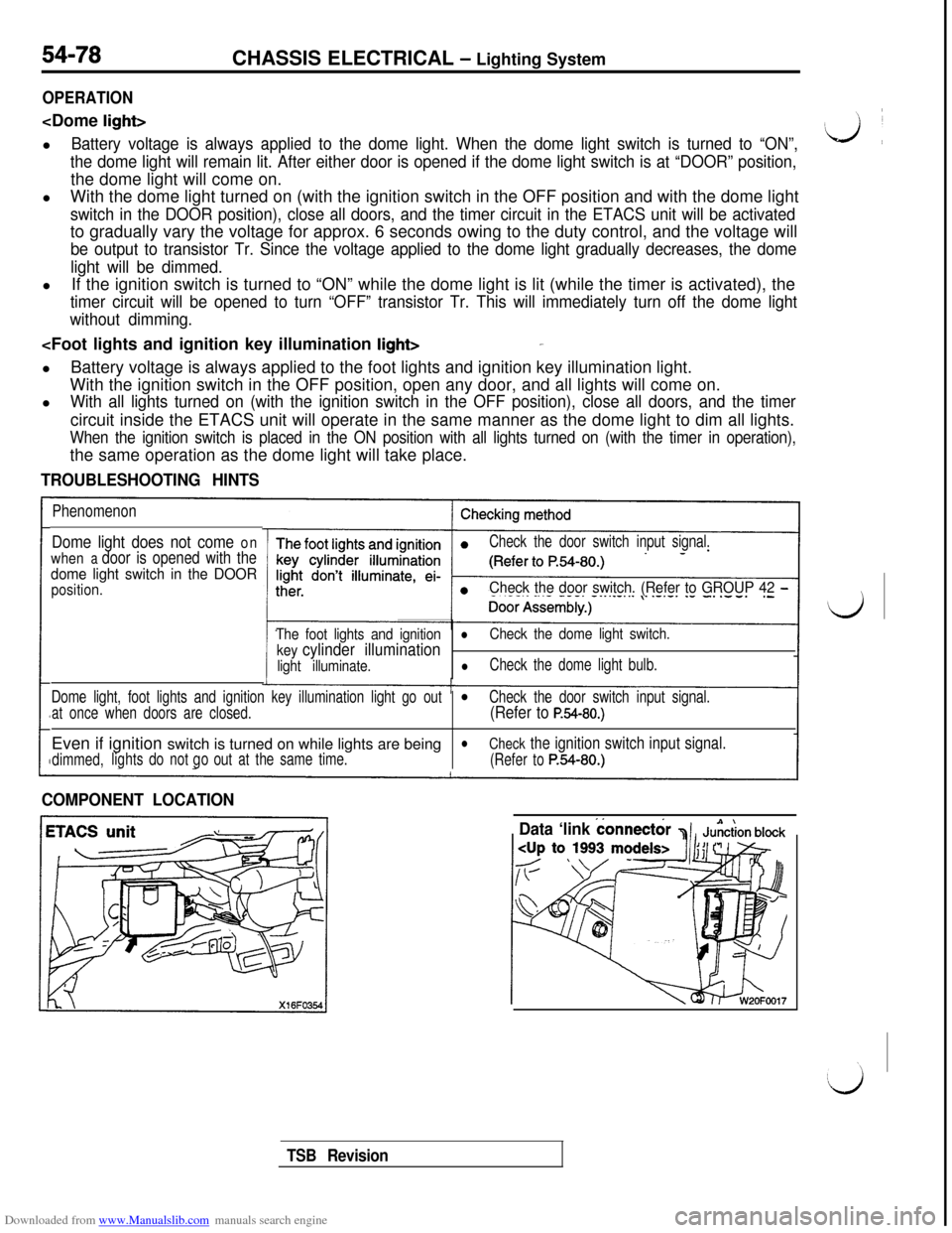
OPERATION
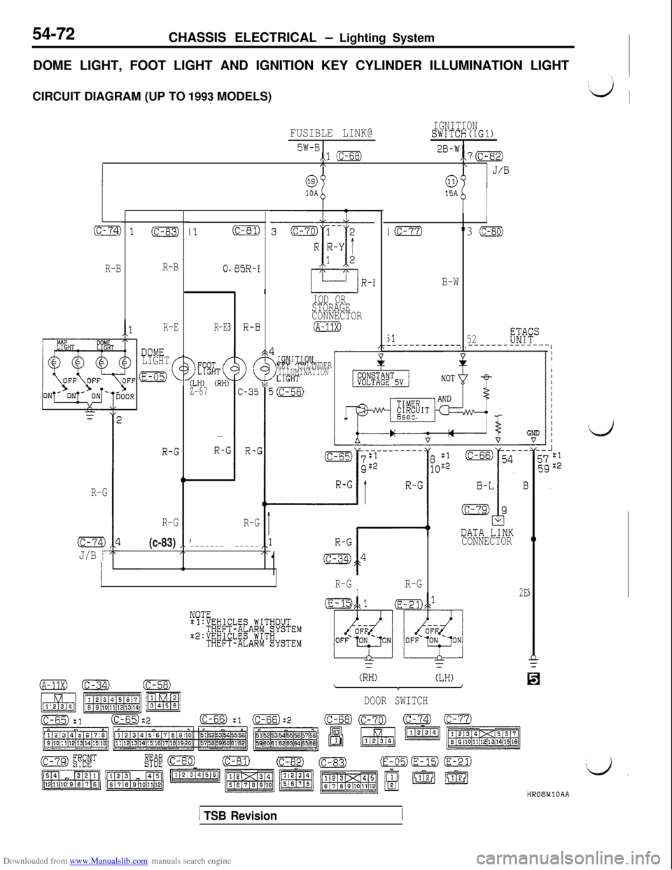
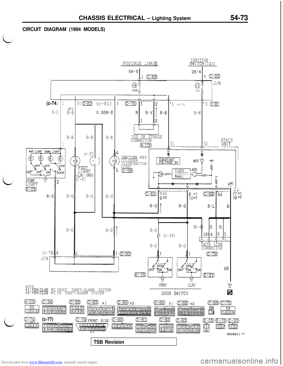
Battery voltage is always applied to the dome light. When the dome light switch is turned to “ON”,
the dome light will remain lit. After either door is opened if the dome light switch is at “DOOR” position,the dome light will come on.
lWith the dome light turned on (with the ignition switch in the OFF position and with the dome light
switch in the DOOR position), close all doors, and the timer circuit in the ETACS unit will be activatedto gradually vary the voltage for approx. 6 seconds owing to the duty control, and the voltage will
be output to transistor Tr. Since the voltage applied to the dome light gradually decreases, the dome
light will be dimmed.lIf the ignition switch is turned to “ON” while the dome light is lit (while the timer is activated), the
timer circuit will be opened to turn “OFF” transistor Tr. This will immediately turn off the dome light
without dimming.
With the ignition switch in the OFF position, open any door, and all lights will come on.
l
With all lights turned on (with the ignition switch in the OFF position), close all doors, and the timercircuit inside the ETACS unit will operate in the same manner as the dome light to dim all lights.
When the ignition switch is placed in the ON position with all lights turned on (with the timer in operation),the same operation as the dome light will take place.
TROUBLESHOOTING HINTS
Phenomenon
Dome light does not come on
when
a door is opened with the
dome light switch in the DOOR
position.
Check the door switch input signal.
Check the door switch. (Refer to GROUP 42 -
The foot lights and ignitionl
key cylinder illumination
Check the dome light switch.
light illuminate.
lCheck the dome light bulb.
Dome light, foot lights and ignition key illumination light go out
l
at once when doors are closed.Check the door switch input signal.(Refer to P.54-80.)Even if ignition switch is turned on while lights are being
l
dimmed,lightsdo notout at the same time.
Check the ignition switch input signal.
go
(Refer toP.54-80.)
COMPONENT LOCATION
Data ‘link
connect&
TSB Revision
Page 576 of 738
Downloaded from www.Manualslib.com manuals search engine With voltmeterData link connector
’‘:’ ’ ’- Data linkGround ETA,CS 21~33300002230
54-80CHASSIS ELECTRICAL - Lighting System
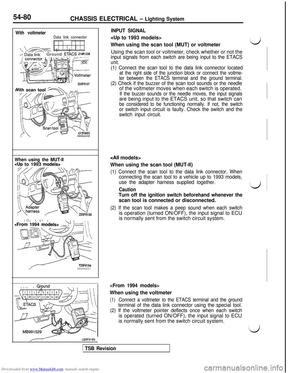
INPUT SIGNAL
When using the scan tool (MUT) or voltmeter
Using the scan tool or voltmeter, check whether or not the
input signals from each switch are being input to the ETACS
unit.
(1) Connect the scan tool to the data link connector located
at the right side of the junction block or connect the voltme-
ter between the ETACS terminal and the ground terminal.
(2) Check if the buzzer of the scan tool sounds or the needleof the voltmeter moves when each switch is operated.
If the buzzer sounds or the needle moves, the input signalsare being input to the ETACS unit, so that switch can
be considered to be functioning normally. If not, the switch
or switch input circuit is faulty. Check the switch and the
switch input circuit.
When using the MUT-II
cup to 1993 models>
Y2OFOl6400002231
#\,I kQwnd\ \U2OFO163
When using the scan tool (MUT-II)
(1) Connect the scan tool to the data link connector. When
connecting the scan tool to a vehicle up to 1993 models,
use the adapter harness supplied together.
Caution
Turn off the ignition switch beforehand whenever thescan tool is connected or disconnected.
(2) If the scan tool makes a peep sound when each switchis operation (turned ON/OFF), the input signal to ECU
is normally sent from the switch circuit system.
(1)Connect a voltmeter to the ETACS terminal and the ground
terminal of the data link connector using the special tool.
(2) If the voltmeter pointer deflects once when each switchis operated (turned ON/OFF), the input signal to ECU
is normally sent from the switch circuit system.
Ii3
\ ~
id ~
!Lj
[ TSB Revision
Page 577 of 738
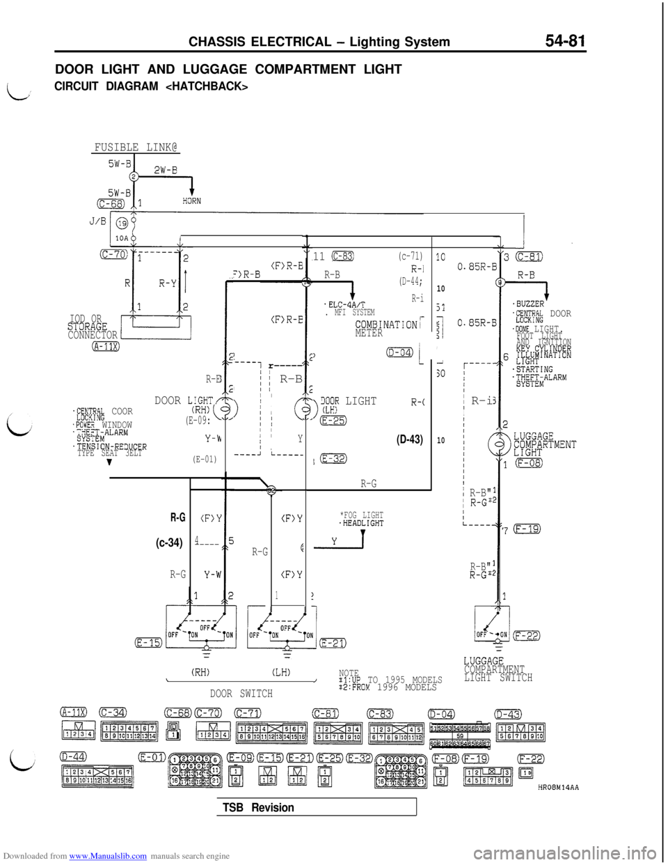
Downloaded from www.Manualslib.com manuals search engine CHASSIS ELECTRICAL - Lighting System54-81DOOR LIGHT AND LUGGAGE COMPARTMENT LIGHT
LCIRCUIT DIAGRAM
FUSIBLE LINK@I
I
IOD ORSTaRAGE
CONNECTOR
(A-11X)
R-E
DOOR LIGHT/.f;;$yik COOR
.POWER WINDOW';;gX$MALARM
.TENSION-RE3UCER
TYPE SEAT 3ELT
v
(RH)(E-09:
Y-b
(E-01)
R-G
(c-34)
R-G
(F)Y
4-----
(F>R-E=)R-B
(F>R-E
)
-----1 r-----/
,; ~ R-BII /
>
I/ II I1; cII II IIY/ ,----Ji-----
R-G
(F)Y
E
(F)Y
1
11 (c-83)(c-71)
R-B
i
(D-44;
.ELCdA/TR-i
. MFI SYSTEM
COMBINATIONrMETER
)
>
iX;? LIGHTR-c
m
(D-43)
l(E-32)
R-G
*FOG LIGHT.HEADLIGHT
-2-l
1C
10
51
$I1',1
SO
10
(RH)(LH)NOTE\/:l:UP TO 1995 MODELS
DOOR SWITCH%2:FROM 1996 MODELS
0.85R-1
0.85R-I
r----'/I/II
R-iI
I
/IIIII/(III/I
i R-B"I R-G":
/IL----.
R-B"R-G";
=I.BUZZER'L"RN;RP.k DOOR
.DOME LIGHT.FOOT LIGHT
AND IGNITION
KEY.CYLINDER6 &L#'NAT'ON
-STARTING.;yE;;iALARMj
7(F-19)
LUGGAGE
COMPARTMENT
LIGHT SWITCH
HR08M14AA
TSB Revision
Page 578 of 738
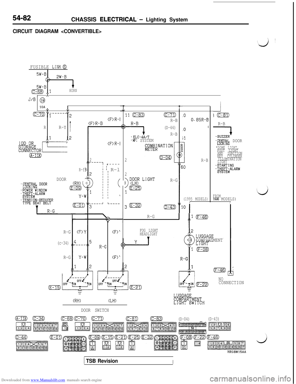
Downloaded from www.Manualslib.com manuals search engine 54-82CHASSIS ELECTRICAL. - Lighting System
CIRCUIT DIAGRAM
FUSIBLE LINKG
2W-B
5W-B(c-68) ,,lHORN/ m
J/B @
10A\I\,
(C-70)y-----3
I
(RR-Y
-1
(A-31X)
-2 I
R-f3
DOORC
R-B
QJ-fE#& DOOR
*DOME LIGHT,FOOT LIGHT
AND IGNITION
KEY CYLINDER
ILLUMINATION
LIGHT
-STARTINGjtjg&ALARM
t
11 (C-83)(c-71)
9
R-B
(D-44)
.ELC-4A/TR-B
.MFI SYSTEM
2
.O0.85R-B(F)R-I:F)R-B
(F)R-I
2
_----7 r----
I' I R-l2II
011 (
1 I/
I I\
.Ot
jl
3R-B
(1995 MODELS)
30
;0
2
R-G
FROM1996 MODELS),.----JI-----
R-G
' f
l(F-46)
R-G
(c-34)
R-G
FOG LIGHT
HEADLIGHT
vCOMPARTMENT
(F>‘
I---_
(F>‘
(F)'
NOCONNECTION
r=
(RH)(LH)
DOOR SWITCH
o(C-34)(c-68)Fml m(c-81)(c-83)
(D-04)(D-43)
HROBM15AA
1 TSB RevisionI