Ignition MITSUBISHI 3000GT 1994 2.G Workshop Manual
[x] Cancel search | Manufacturer: MITSUBISHI, Model Year: 1994, Model line: 3000GT, Model: MITSUBISHI 3000GT 1994 2.GPages: 738, PDF Size: 35.06 MB
Page 581 of 738
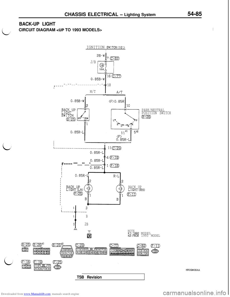
Downloaded from www.Manualslib.com manuals search engine BACK-UP LIGHTCHASSIS ELECTRICAL
- Lighting System54-85
i./’CIRCUIT DIAGRAM CUP TO 1993 MODELS>I
IGNITION SWITCH(IG1)
I
J/B
iir-----_--__-__________-_-
1
M/TI
I
I
L_-----------_--_-_------110r-----
---__--__-_____IIII
I
I0.85R-L
BACK UP
LIGHTCRH)
IBi-~~~~~~~~~~
B
!
2B
PARK/NEUTRAL
POSITION SWITCH
(8-26)
NOTEx1:1992 MODELX2:FROM 1993 MODEL
HROSMOGAA
TSB Revision
Page 582 of 738
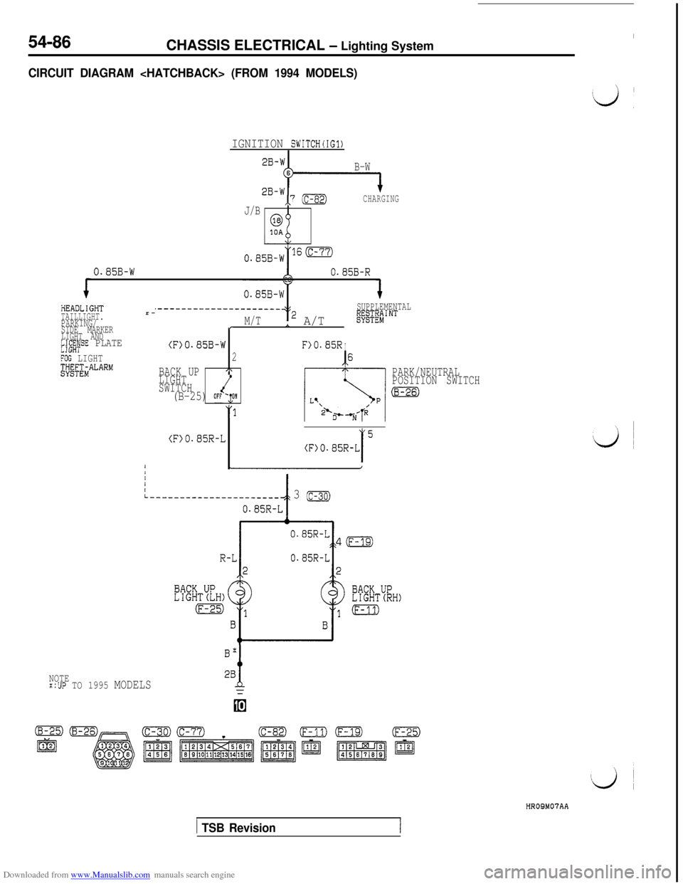
Downloaded from www.Manualslib.com manuals search engine 54-86ICHASSIS ELECTRICAL
- Lighting System
CIRCUIT DIAGRAM
IGNITION SWITCH(IG1)
B-W
2B-W,,7 (c-8)CHARGING
J/B
6310A
0.85B-WlS(c-77)
0.85B-W0.85B-R
PlEADLIGHTTAILLIGHT.PARKING/
SIDE MARKER
LIGHT AND
k];$ySE PLATE
FOG LIGHT;;k#TALARMr-
.---------------------SUPPLEMENTAL
M/T2 A/Tf$Eg$giiNT
r
(F)O.85B-W
2
BACK UP,\
LIGHT
SWITCH
(B-25) OFF&
(F)O.85R-L
F>O.85RI
I6
PARK/NEUTRAL
POSITION SWITCH
I
5
(F>O.85R-LIII
:-___-____-____________
t
3 (c-30)
O.S5R-L
0.85R-L
NOTE::UP TO 1995 MODELS
B"
f28
1 TSB Revision
HR09M07AA
Page 583 of 738
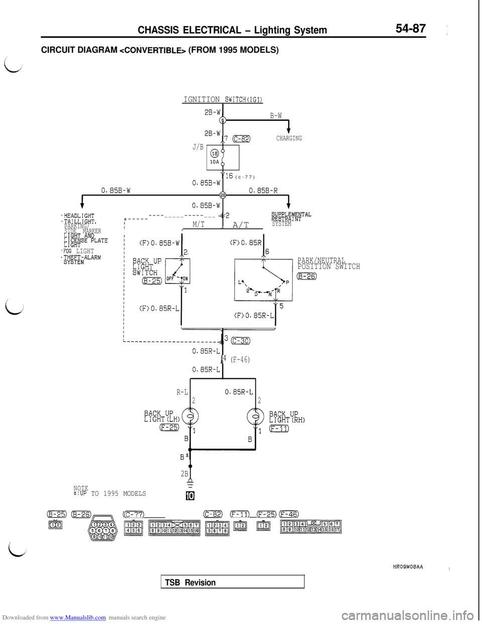
Downloaded from www.Manualslib.com manuals search engine CHASSIS ELECTRICAL - Lighting System54-87 ~
CIRCUIT DIAGRAM
IGNITION SWITCH(IG1)
B-W
2B-W,,7 (c-82)CHARGING
J/B
0.85B-W"16 (c-77)
O.S5B-W28)O.B5B-R
0.85B-W
.!lEADLIGHTr---------_____-----___.TA!LLIGHT.452
PARKING/1M/T
;~$..t!$TAL
I,, A/TSYSTEM
SIDE MARKERII
.FOG LIGHT
PARK/NEUTRALPOSITION SWITCH
0.85R-L
5>4 (F-46)
0.85R-L
R-L
0.85R-L
22
NOTE=:UP TO 1995 MODELS
0
2B
n
(B-25)(c-30)cm(c-82) (F-11) (rn(F-46)
f?EJ~1’~‘~~~ m -1
TSB RevisionHROSMOEAA
I
Page 584 of 738
Downloaded from www.Manualslib.com manuals search engine 54-88CHASSIS ELECTRICAL - Lighting System
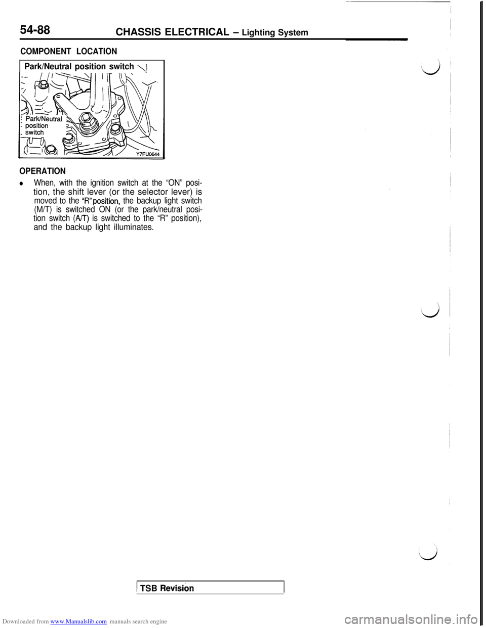
COMPONENT LOCATION
Park/Neutral position switch 11
OPERATION
lWhen, with the ignition switch at the “ON” posi-tion, the shift lever (or the selector lever) is
moved to the “R”position, the backup light switch
(M/T) is switched ON (or the park/neutral posi-
tion switch
(A/T) is switched to the “R” position),
and the backup light illuminates.
1 TSB Revisibn
Page 585 of 738
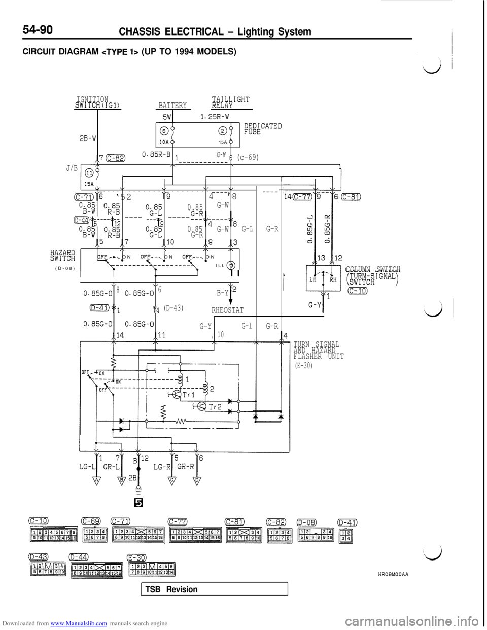
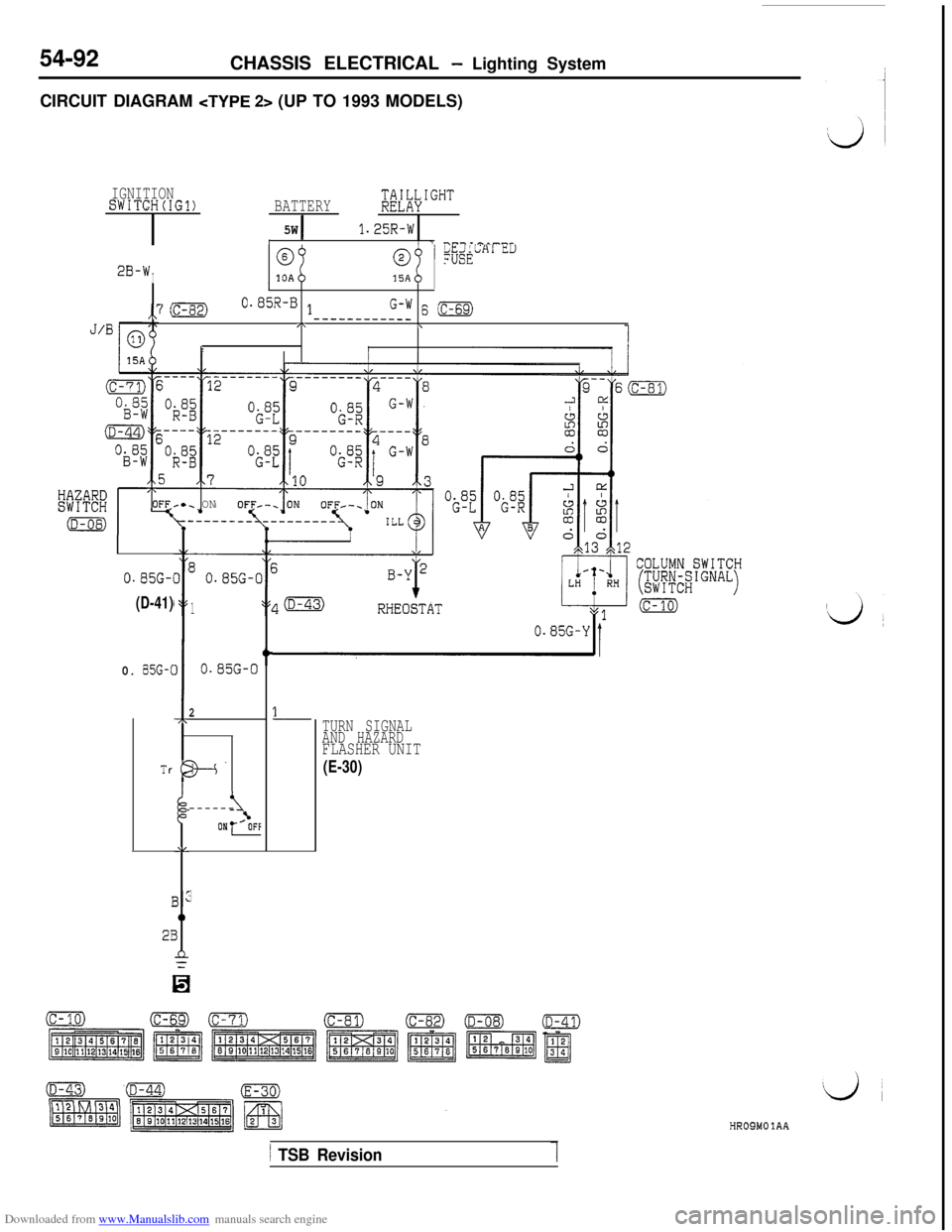
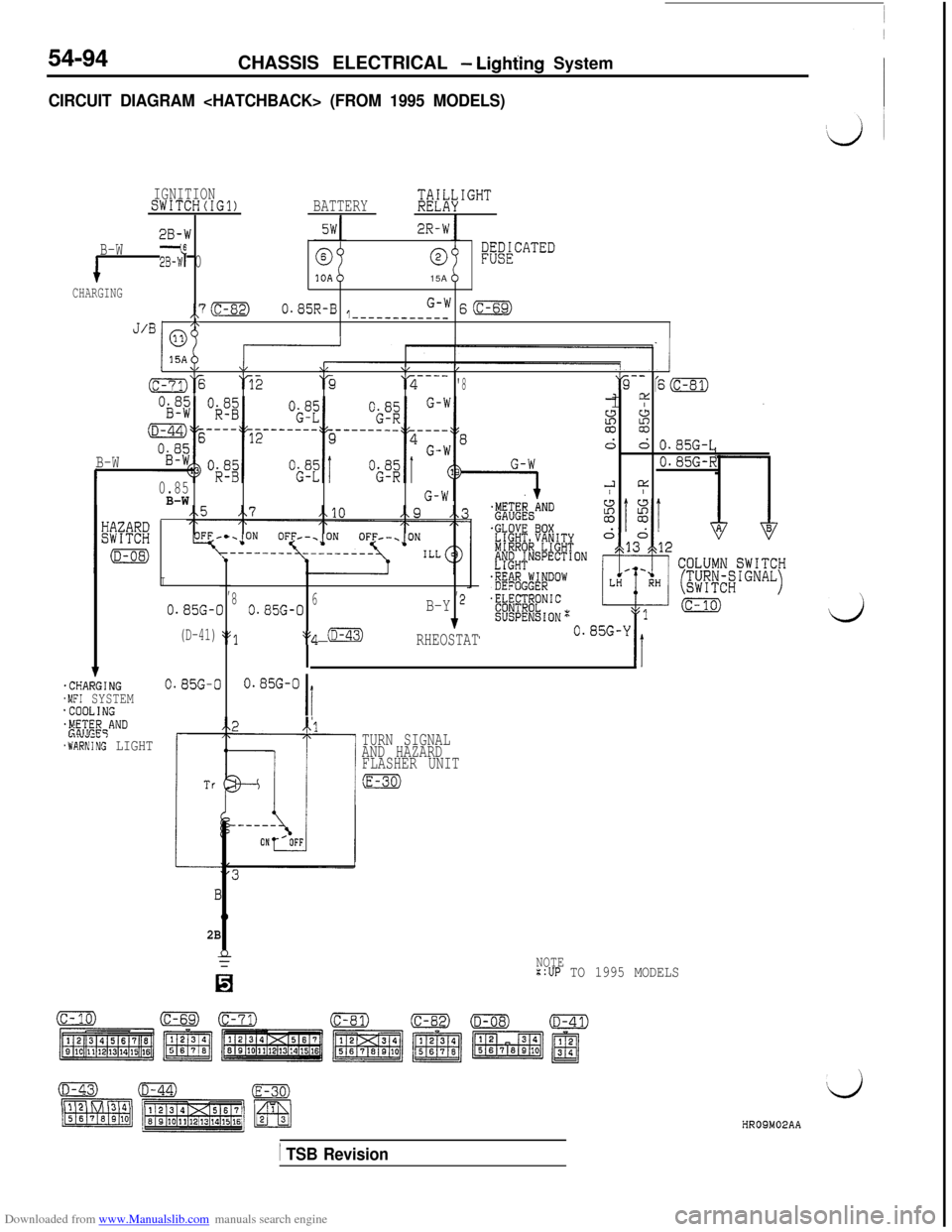
Downloaded from www.Manualslib.com manuals search engine 1. When operation is normal
l
When the ignition switch is switched to the
ON position, battery voltage is applied (viathe multipurpose fuse (11) and hazard
switch) to the turn-signal and hazard flasher
unit.l
When the turn-signal switch is switched to
the LH position,
Trl (within the flasher unit)
is switched ON and OFF repeatedly.
Then the contacts of the relay 1 (also within
the flasher unit) repeatedly switch from ON
to OFF, causing the turn-signal lights and
turn-signal indicator light LH to flash.l
When the turn-signal switch is switched to
the RH position, Tr2 (within the flasher unit)
is switched ON and OFF repeatedly.Then the contacts of relay 2 (also within
the flasher unit) repeatedly switch from ON
to OFF, causing the turn-signal lights and
turn-signal indicator light RH to flash.2. If one of the bulbs is burned out
lIf the LH (or RH) turn-signal light bulb is
burned-out, the resistance of the turn-signalcircuit as a whole increases, resulting in
Lshorter ON and OFF intervals of the LHTrl (or RH Tr2) and a higher flashing rateof the LH lights (or RH lights).CHASSIS ELECTRICAL
- Lighting System54-89
TURN-SIGNAL LIGHT AND HAZARD
L
LIGHT
OPERATION
ed to the “ON” position, the relay contactof the turn signal and hazard flasher unit
is switched ON and OFF repeatedly, in thesame manner as for the operation of the
turn-signal lights, and the left and right turn-
signal lights and turn-signal indicator lights
simultaneously flash repeatedly.
NOTE
(1) The number of flashes of the hazard-warn-
ing lights does not change if there is dam-
aged or disconnected wiring of one light.
(2)The light automatic shut-OFF system is valid
for the illumination light of the hazard switch.(Refer to
P.54-37.)
TROUBLESHOOTING HINTS
1.The turn-signal lights and hazard-warning lightsdo not operate at all.
l Check the hazard switch contact (power
supply side).l Check the turn-signal and hazard flasher
unit.2. All turn-signal lights at the left (or right) side
do not function.
(1) The hazard-warning lights function normal-
ly-lCheck the hazard switch contact (turn-
signal side).l Check the turn-signal switch.
3.The number of flashes of the turn-signal lights
is excessive.l Check the bulbs.
4. The hazard-warning lights do not function.
(1) The turn-signal lights function normally.l
Check the hazard switch contact (haz-
ard-warning light side).
NOTE
For the troubleshooting hints of the automatic lightshut-OFF system, refer to
P.54-37.
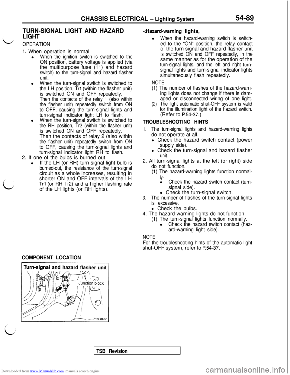
COMPONENT LOCATION
TSB Revision
Page 586 of 738
Downloaded from www.Manualslib.com manuals search engine 54-90CHASSIS ELECTRICAL - Lighting System
CiRCUlT DIAGRAM
IGNITIONSWITCH(IG1)BATTERY$i[l;\IGHT
1.25R-W
28-W0~&~kCATED15A
,,7 (c-82)0.85R-B lG-w 6 (c-69)----------__J/Blop
,\\1
It115AV\I\/\/\,------------ -------- ----\(c-71,‘% ‘52‘-34 '8
Oi3f$ Ok.8B"O$Z0.85G-W
(D-44)25----2&$ ---- ---'3 -----
op; Ok":"i;";
GIR,z----:'s
0.85G-WG-LG-R,,5,7,,lO,,9,,3
KK%
/\\,\,\OFF-e. ONOFF*-. ONOFF/-. ON
(D-08)ILL
----
G-R
IIII I
*4,
0.85G-080.85G-06B-Y2
(D-41)y3:4 (D-43)I
RHEOSTAT
0.85G-00.85G-0
G-YG-l
,,14,,ll10,
G-RCOLUMN SWITCH
(c-10)
LG-I$GR-$$' LG-i$k$
n
TURN SIGNAL
AND HAZARD
FLASHER UNIT
(E-30)HR09MOOAA
TSB Revision
Page 588 of 738
Downloaded from www.Manualslib.com manuals search engine 54-92CHASSIS ELECTRICAL - Lighting System
CIRCUIT DIAGRAM
IGNITIONSWITCH(IG1)BATTERY$E"Lh\IGHT
5W1.25R-WI/ 1 -.---^^^^r
2B-WI
@@!p&LHl LLI
10A15AI
,,7 (c-82)0.05R-0 1G-W 6 (c-69)------__--__J/BI\\
rI
0.85G-1
(D-41)
,\OFFc.. ON
0. 85G-C
Tr
I
2I
II
I
-7r
I;
AL
3:
0
3
n=
3
80.85G-C
1
0.85G-0
2
t
B--’
\------ON-
0.85G-Y
1TURN SIGNAL
AND HAZARD
FLASHER UNIT
(E-30)
HROSMOlAA
1 TSB Revision
Page 590 of 738
Downloaded from www.Manualslib.com manuals search engine 54-94CHASSIS ELECTRICAL - Lighting System
CIRCUIT DIAGRAM
IGNITIONSWITCH(IG1)BATTERY;di\IGHT
28-W2R-W
B-W2B-W6 00l;akCATED15A
CHARGING
,,7(c-82)0.85R-B1G-WS(c-69)-----------_/\J’BI no
1.CHARGING.MFI SYSTEM'COOLING$F!;E$qAND
.WARNIiG LIGHT
I,,
0.85G-C810.85G-06B-Y 2
(D-41)::q (D-43)1
‘$1RHEOSTAT
0.85G-00.85G-0
Ii
I \"w\/\/b/---- -------- --------a‘% ‘52‘3---_‘2'8"9-- '6m2 DiI I2
si
d: O.BSG-L
B-W0.85G-R
0.852 L1:
B-W/ I
2B
TURN SIGNAL
AND HAZARD
FLASHER UNIT
:E-30)
NOTE::UP TO 1995 MODELS
dHROSM02AA
/ TSB Revision
Page 592 of 738
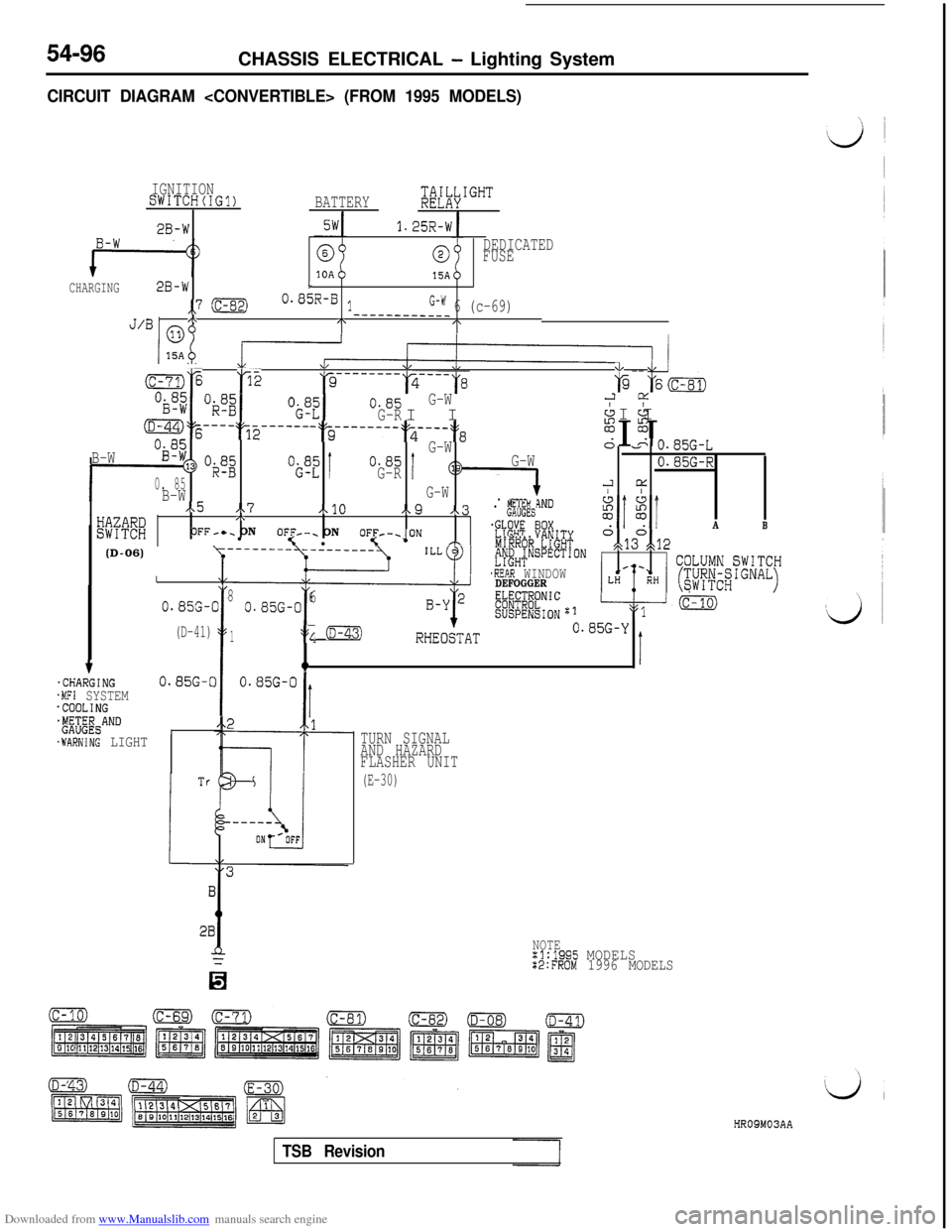
Downloaded from www.Manualslib.com manuals search engine 54-96CHASSIS ELECTRICAL - Lighting System
CIRCUIT DIAGRAM
IGNITIONSWITCH(IG?)BATTERY;&IGHT
2B-W1.25R-W
0DEDICATED
FUSE
15ACHARGING2B-wL
,,7 :c-82)0.85R-B lG-W 6 (c-69)/\J’BI mo
-___----____/\I\
B-W
f-
D-44)% ---- :T2 ------ -$~e---m--.~s---:~8%I I&
Og;G-WA&n
*3> “$2“i;“=!0.85
0. 85G-RI
B-WG-W
I/x5 .\7A10e9 x.3wmj,\. p!&'
OFF-c. ON
lOFF--. ON5 loF1;F-~oN m'R% thnrnnnb
G-W
1. .----iND
- - v.85G-L
0.85G-R
2 cc/ I.
E(D-06)IOX
'E%T'~~~J~~SPECTION
.REAR WINDOWDEFOGGERE#@;.NIC
SUSPENSIONzl
A
o,d3°gt12
B
\y---- --------
:c-?:,jE p2w
*\L &I--
a-7j% 166
“$ZI0.85G-W
G-RI I2 CL
& &I I
I
0.8%-(
(D-41)
38
I
0.85G-06
1:s; (D-43)RHEObAT0.85G-Y
qIt.CHARGING0.85G-C.MFI SYSTEM.COOLING+&$&ANDI.WARNING LIGHT
28
TURN SIGNAL
AND HAZARD
FLASHER UNIT
(E-30)
NOTEx1:1995 MODELSX2:FROM 1996 MODELS
HR09M03AA
TSB Revision
Page 612 of 738
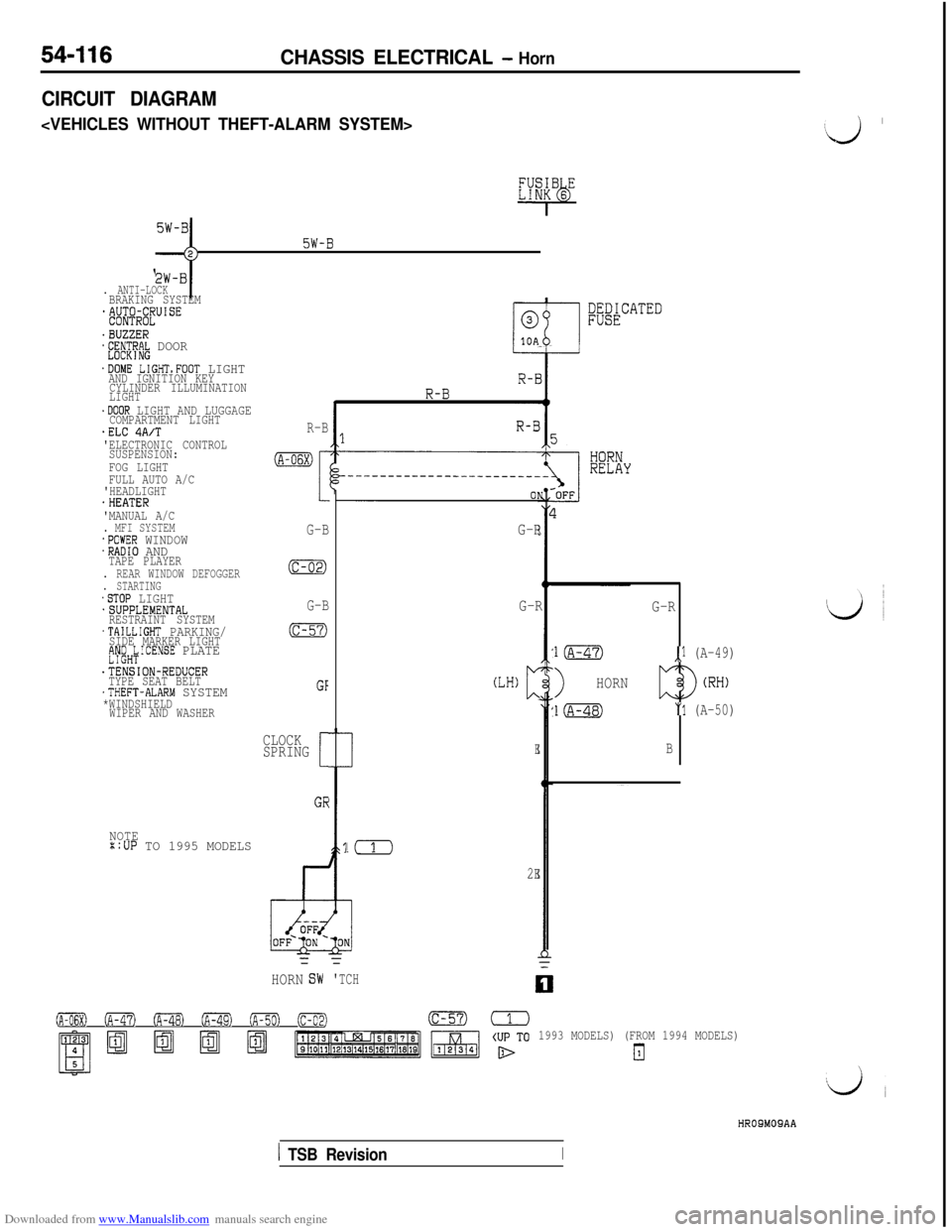
Downloaded from www.Manualslib.com manuals search engine 54-116CHASSIS ELECTRICAL - Horn
CIRCUIT DIAGRAM
c
5W-B;;-j
. ANTI-LOCKBRAKING SYSTEM*&$@lJUISE
.BUZZER*E;~CT~R~ DOOR
.DOME LIGHTsFOOT LIGHTAND IGNITION KEY
CYLINDER ILLUMINATION
LIGHT
.DOOR LIGHT AND LUGGAGECOMPARTMENT LIGHT.ELC 4A/T'ELECTRONIC CONTROL
SUSPENSION:
FOG LIGHT
FULL AUTO A/C
'HEADLIGHT
.HEATER
'MANUAL A/C
. MFI SYSTEM.POWER WINDOW.RADIO ANDTAPE PLAYER. REAR WINDOW DEFOGGER. STARTING.STOP LIGHT.SUPPLEMENTAL
RESTRAINT SYSTEM
.TAILLIGHT PARKING/SIDE MARKER LIGHTfJy;H;ICENSE PLATE
.TENSION-REDUCER
TYPE SEAT BELT
.THEFT-ALARM SYSTEM*WINDSHIELD
WIPER AND WASHER
NOTE::UP TO 1995 MODELS
R-B
(A-06X)
I
G-B
(c-02)
G-B
(c-57)
GF
CLOCK
SPRING
[
GE
;;&CATED
G-R
!(
2E=
HORNG-R
(LH)c
E
=
'TCH
G-R
l(A-47),l (A-49)
>HORN
l(A-48)"1 (A-50)
B
0 (A-47) oFa (A-49) ofiml (c-02)(c-57)=
1993 MODELS) (FROM 1994 MODELS)
El
‘J ’
HROSMOSAA
1 TSB RevisionI