Ignition MITSUBISHI 3000GT 1994 2.G Workshop Manual
[x] Cancel search | Manufacturer: MITSUBISHI, Model Year: 1994, Model line: 3000GT, Model: MITSUBISHI 3000GT 1994 2.GPages: 738, PDF Size: 35.06 MB
Page 519 of 738
Downloaded from www.Manualslib.com manuals search engine LJ
/
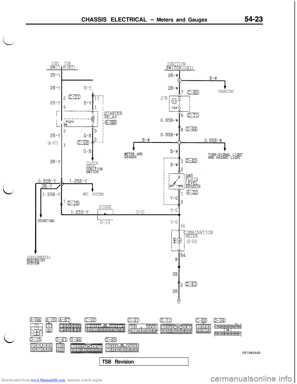
:i:CHASSIS ELECTRICAL
- Meters and Gauges54-23
IGNISWI?
2B-k
2B-k
2B-k
r
2B-Y
(A-67)
2B-Y
jTARTING
SUPPLEMENTALl@TE"#'NT
IONH(ST)
B-YI
z(c-31)17-1
4B-Y I1 /
f
/STARTER--------__;RELAYsPOFFINjm
CLUTCH
PEDAL
&j+$HON
1.25B-Y
IMFI SYSTEM
IGNITIONSWITCH(IG1)I
CHARGING
J/B
s(c-71)
0.85B-W
Y
s(D-44)
0.85B-W
lmDIODE
1.25B-Yu(Y-G)Y-G0
D-10Y-G
66
A COMBINATIONMETER90(D-04)
HRlOMOIAB
TSB Revision
Page 521 of 738
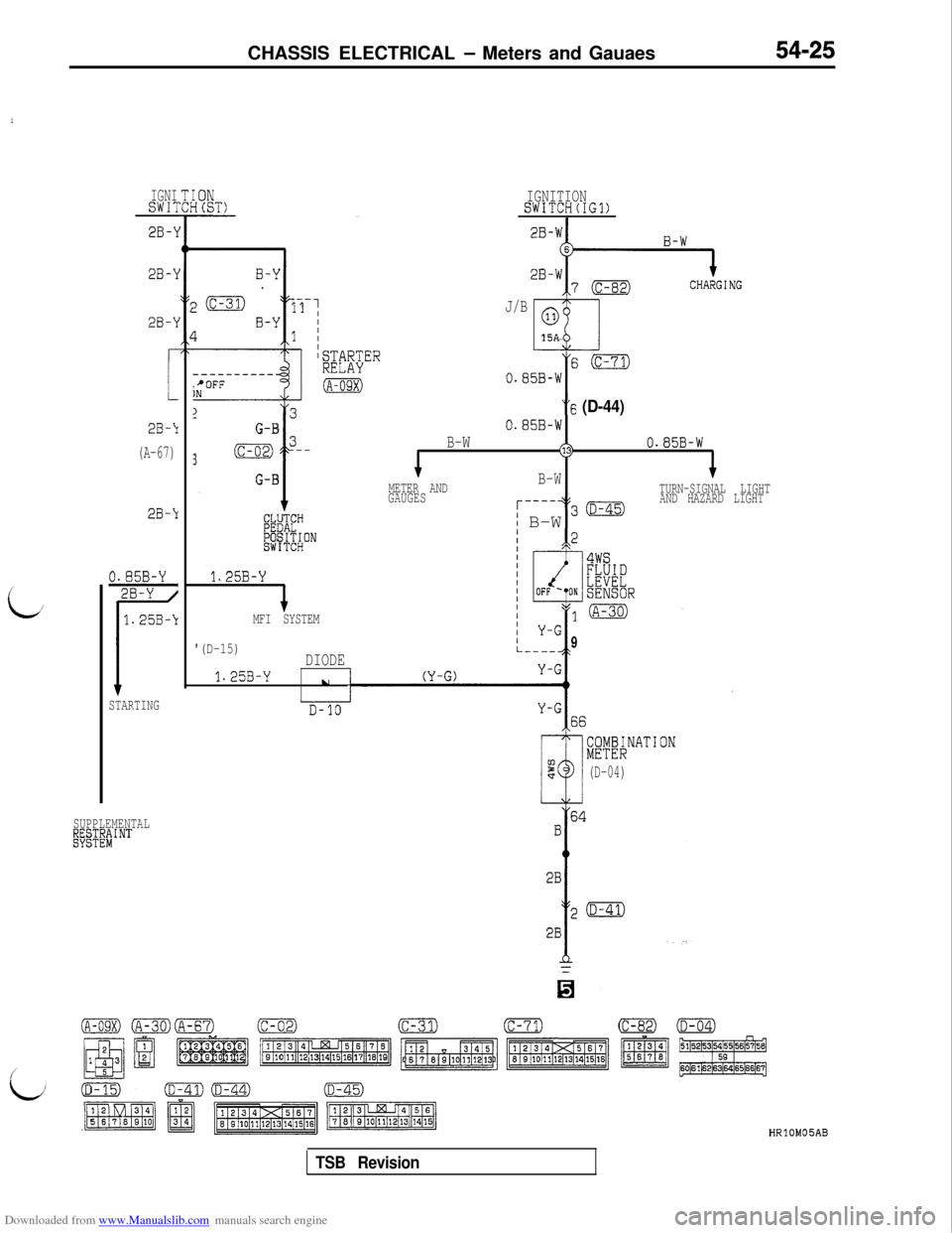
Downloaded from www.Manualslib.com manuals search engine CHASSIS ELECTRICAL - Meters and Gauaes
i
L/
IGNISW17
2B-\1
28-l
2B-\I
2B-‘1
(A-67)
2B-Y
STARTING
SUPPLEMENTAL
~E~&~J$NT
----------.+OFFIN
13
i
G-B
3(c-02) 3--
G-B
1.25B-Y
+MFI SYSTEM
'(D-15)DIODE
1.25B-Yu
I
IGNITIONSWITCH(IG1)
J/B
ml
0
15A“6
(D-44)
0.85B-W
B-W(130.85B-W
METER AND
GAUGESB-WTURN-SIGNAL LIGHT
r----+$30AND HAZARD LIGHT
i B-W
9
i;yEKNATION
(D-04)
HRlOM05AB
TSB Revision
Page 523 of 738
Downloaded from www.Manualslib.com manuals search engine I,;CHASSIS ELECTRICAL
- Meters and Gauges54-27
c I\\ zl6F024;
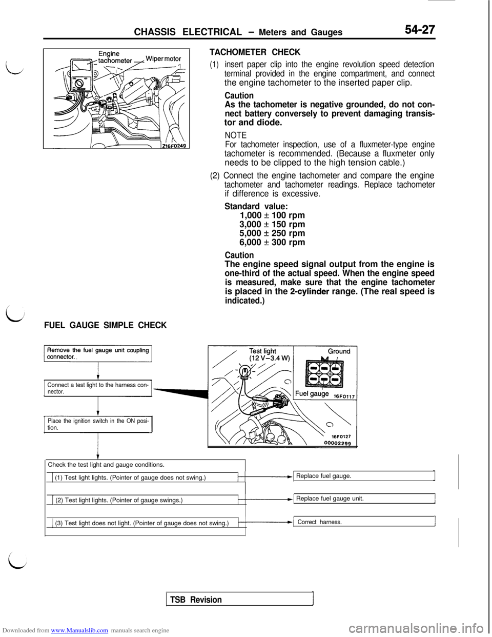
L:FUEL GAUGE SIMPLE CHECKTACHOMETER CHECK
(1)insert paper clip into the engine revolution speed detection
terminal provided in the engine compartment, and connectthe engine tachometer to the inserted paper clip.
Caution
As the tachometer is negative grounded, do not con-
nect battery conversely to prevent damaging transis-tor and diode.
NOTE
For tachometer inspection, use of a fluxmeter-type engine
tachometer is recommended. (Because a fluxmeter onlyneeds to be clipped to the high tension cable.)
(2) Connect the engine tachometer and compare the engine
tachometer and tachometer readings. Replace tachometer
if difference is excessive.
Standard value:1,000
f 100 rpm
3,000
+ 150 rpm
5,000
f 250 rpm
6,000
f 300 rpm
CautionThe engine speed signal output from the engine is
one-third of the actual speed. When the engine speed
is measured, make sure that the engine tachometeris placed in the
2-cylinder range. (The real speed is
indicated.)
Connect a test light to the harness con-nector.
Place the ignition switch in the ON posi-
tion.Check the test light and gauge conditions.
1 (1) Test light lights. (Pointer of gauge does not swing.)/-.-I Replace fuel gauge.
[ (2) Test light lights. (Pointer of gauge swings.)/-.--I Replace fuel gauge unit.1
1 (3) Test light does not light. (Pointer of gauge does not swing.)k-1 Correct harness.I
TSB Revision
Page 525 of 738
Downloaded from www.Manualslib.com manuals search engine CHASSIS ELECTRICAL - Meters and Gauaes
i
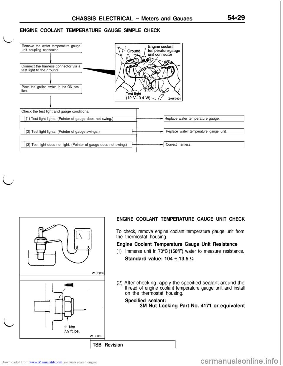
ENGINE COOLANT TEMPERATURE GAUGE SIMPLE CHECKConnect the harness connector via a
test light to the ground.
Remove the water temperature gauge
unit coupling connector.
t
Place the ignition switch in the ON posi-tion.
I
(12 v’3.4 w) \ //Z16FO13lCheck the test light and gauge conditions.
i(1) Test light lights. (Pointer of gauge does not swing.)_____c Replace water temperature gauge.
[ (2) Test light lights. (Pointer of gauge swings.)Replace water temperature gauge unit.
[ (3) Test light does not light. (Pointer of gauge does not swing.)/-------I Correct harness.
ENGINE COOLANT TEMPERATURE GAUGE UNIT CHECK
To check, remove engine coolant temperature gauge unit from
the thermostat housing.
Engine Coolant Temperature Gauge Unit Resistance
(1)Immerse unit in 70°C (158OF) water to measure resistance.Standard value: 104
f 13.5 Sz(2) After checking, apply the specified sealant around the
thread of engine coolant temperature gauge unit and install
on the thermostat housing.
Specified sealant:3M Nut Locking Part No. 4171 or equivalent
TSB RevisionI
Page 526 of 738
Downloaded from www.Manualslib.com manuals search engine 54-30CHASSIS ELECTRICAL - Meters and Gauges
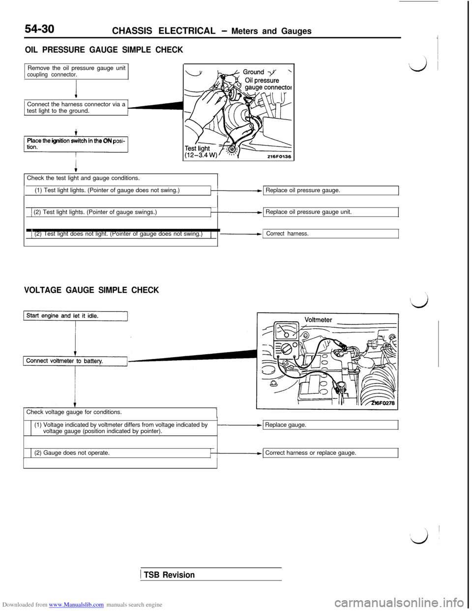
OIL PRESSURE GAUGE SIMPLE CHECKRemove the oil pressure gauge unit
coupling connector.Connect the harness connector via a
test light to the ground.
-1Place the ignition switch in the ON posi-Check the test light and gauge conditions.
(1) Test light lights. (Pointer of gauge does not swing.)
k-1 Replace oil pressure gauge.
1 (2) Test light lights. (Pointer of gauge swings.)k-1 Replace oil pressure gauge unit.
1 (2) Test light does not light. (Pointer of gauge does not swing.)/-1 Correct harness.
VOLTAGE GAUGE SIMPLE CHECKCheck voltage gauge for conditions.
(1) Voltage indicated by voltmeter differs from voltage indicated by
voltage gauge (position indicated by pointer).
-1 Replace gauge.
(2) Gauge does not operate.
/--I Correct harness or replace gauge.
1 TSB Revision
Page 533 of 738
Downloaded from www.Manualslib.com manuals search engine CHASSIS ELECTRICAL - Lighting System54-37
i
TROUBLESHOOTING
LHEADLIGHT
OPERATION
lTurn the lighting switch to “HEAD”, and the con-
tact point of the headlight relay will be closedto turn “ON” the headlight relay.
lWhen the dimmer switch is placed in the LO
position, the headlight low-beams go on. On
vehicles up to 1993 model, when the switch
is placed in the HI position, the headlight high-
beams go on. On vehicles from 1994 model,when the switch is placed in the HI position,
the headlight high-beams and low-beams go
on.
When the high-beam is lit or when the passing
switch is activated, the high-beam indicator lightwill be lit.
If the driver’s door is opened after the ignition
switch is turned to “OFF” or the ignition switchis turned to “OFF” after the driver’s door is
opened when the headlights are lit, the currentwhich flows to the coil side of the headlight
relay will be cut off by the light automatic shut-OFF unit opening the contact point, and the
headlight relay will be turned “OFF” to automati-
cally shut off the headlights.l
To turn the headlights on again after they are
automatically shut off, turn the lighting switchto “OFF” once and then back to “HEAD”, or
turn the ignition switch to “ACC” or “ON”, and
the
aut0mati.c shut-OFF will be cancelled andthe current will flow from the light automatic
shut-OFF unit to the coil side of the headlightrelay again to close the contact point. Thus,
the headlight relay will be turned “ON” to turnon the headlights.
NOTEWhen the lighting switch is at “HEAD”, the light
automatic shut-OFF system is valid for tail lights,
parking and side marker lights, license plate light,
illumination light, etc.(Refer to
P.54-70.)
l
When the lighting switch is placed in the HEAD
position, current flows through multi-purpose
fuse (6) to the lighting switch, and the ETACScontrol unit. Then the UP timer circuit in the
LETACS control unit is operated, and currentflows from the ETACS control unit to the U con-tact of the pop-up motor U/D (UP/DOWN)
switch, the coil of the pop-up motor relay and
ground, causing the contacts of the pop-up mo-
tor relay to close.
When the contacts of the pop-up motor relay
close, current flows through the contacts of the
pop-up motor relay to the pop-up motor and
ground, causing the pop-up motor to rotate,
which brings the headlights to the UP position.
The pop-up motor rotates until the automatic
UP stop position is reached, then the contactsof the interlocked U/D (UP/DOWN) switch
change from the U to D contacts. As a result,
the contacts of the pop-up motor relay opento cut off the current supplied to the pop-up
motor. Then the pop-up motor ceases to rotate,
holding the headlights in the UP position.l
When the lighting switch is placed in the TAIL
or OFF position, current flows through the multi-
purpose fuse (6) to the lighting switch, and the
ETACS control unit. Then the DOWN timer cir-
cuit in the ETACS control unit is operated and
current flows from the ETACS control unit to
the DOWN contacts of the pop-up motor U/D
(UP/DOWN) switch, the coil of the pop-up motor
relay and ground, causing the contacts of the
pop-up motor relay to close.
When the contacts of the pop-up motor relay
close, current flows through the contacts of the
pop-up motor relay to the pop-up motor andground, causing the pop-up motor to rotate,
which brings the headlights to the DOWN posi-
tion.
The pop-up motor rotates until the automatic
DOWN stop position is reached, then the con-
tacts of the interlocked U/D (UP/DOWN) switch
change from the D to U contacts. As a result,
the contacts of the pop-up motor relay open
to cut off current supply to the pop-up motor.
Then the pop-up motor ceases to rotate, holding
the headlights in the DOWN position.
When the pop-up switch is placed in the UP
position, current flows through multi-purpose
fuse (6) to the lighting switch, the pop-up switch
and the ETACS control unit, which brings the
headlights to the UP position and holds them
in the UP position just like when they are oper-
ated by the lighting switch.l
When the pop-up switch is placed in the DOWN
position, current flows through the multi-purpose
fuse (6) to the lighting switch, the pop-up switch
and the ETACS control unit, which brings the
headlights to the DOWN position and holds them
in the DOWN position just like when they are
operated by the lighting switch.
TSB Revision
Page 538 of 738
Downloaded from www.Manualslib.com manuals search engine 54-42CHASSIS ELECTRICAL - Lighting System
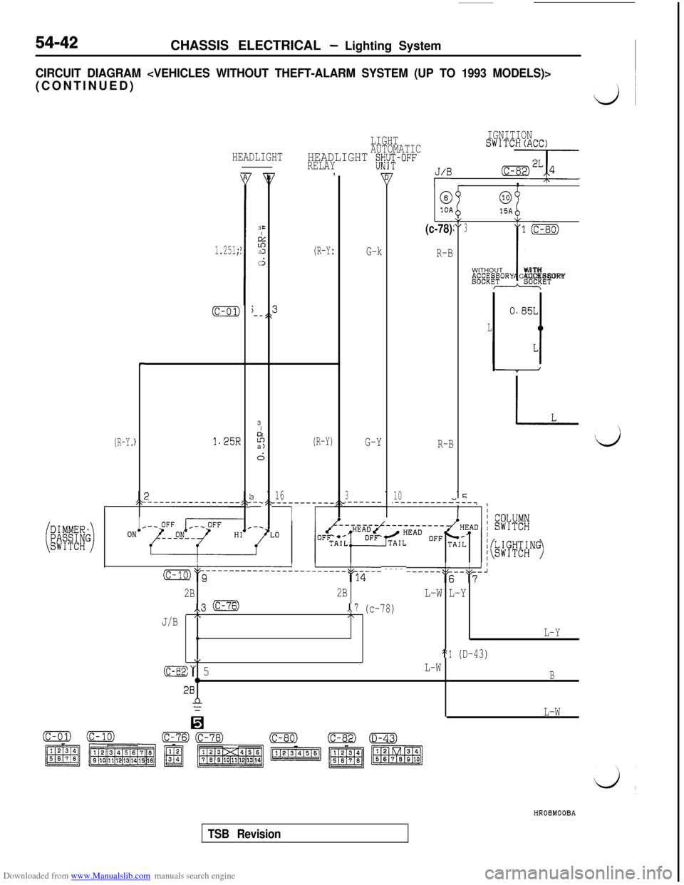
CIRCUIT DIAGRAM
(R-Y.
HEADLIGHT
1.251;
(c-01)j-_,\
L
c
)1.25R
B3
EI
z:aJ
C5
LIGHTIGNITION
AUTOMATICSWITCH(ACC)
HEADLIGHT gWi-i;-OFFRELAY7,J/B -7
(R-Y:I
@0
10A15AY(c-78)\I:3
G-k
R-BWITHOUTP.~~“.~~ORY
-3
I
P;
a(R-Y)G-YR-B
i;3
16310.-_.------.-----------
7 r
-__-7
(c-01)
l(c-80)
iWITH
ACCESSORY*ET
m&c-----------------------~q-6-- ---- ------""s--"F-'
2B2BL-W L-Y
,,3 mx.7 (c-78)
J/B/\I\
t.L-Y
\/St1 (D-43)
(c-82)“ 5L-W
0B28n
0
L-W
HROEMOOBA
TSB Revision
Page 542 of 738
Downloaded from www.Manualslib.com manuals search engine 54-46CHASSIS ELECTRICAL - Lighting System
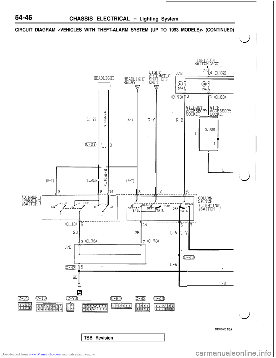
CIRCUIT DIAGRAM
IGNITIONSWITCy(ACC)
HEADLIGHT
(R-Y)
10A
;--
1. 251
(c-01)
(R-Y)
1-25F1
I
5
3
(R-Y)
6:-_-
,O
5---7
B
L-W
0(c-01)0Fz)(c-78)(c-80)(c-82)-HROBMOlBA
TSB Revision
Page 550 of 738
Downloaded from www.Manualslib.com manuals search engine 54-54CHASSIS ELECTRICAL - Lighting System
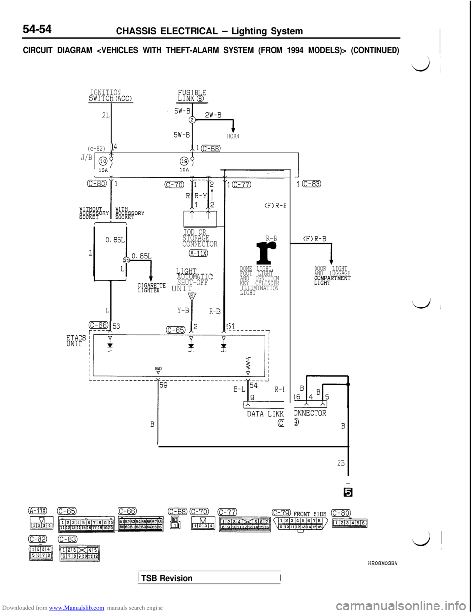
CIRCUIT DIAGRAM
IGNITIONSWITCH(ACC)I
2L2W-B
5W-BHORN
(c-82) ,P/x1=
J/Ba315A10A
IOD ORSTORAGE
CONNECTOR
L
AUTOMATIC
SHUT-OFF
L";@v;$TE UNITE
LYY-BR-E
(F>R-E
R-Br
DOME LIGHT,FOOT LIGHT
AND IGNITION
KEY CYLINDER
ILLUMINATION
LIGHT
51---------7
(F)R-B
2B
DOOR LIGHT
AND LUGGAGE
EWtRTMENT
d,
3NNECTOR
3I3HROBM03BA
1 TSB RevisionI
Page 552 of 738
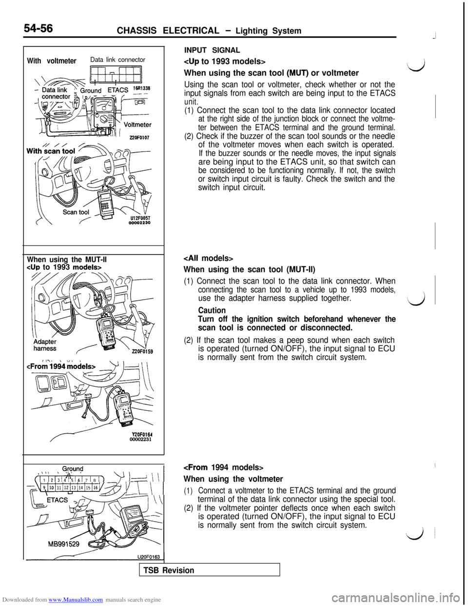
Downloaded from www.Manualslib.com manuals search engine INPUT SIGNALWith voltmeterData link connector
Ii ri7-11
When using the scan tool (MUT) or voltmeter‘d
Using the scan tool or voltmeter, check whether or not the
input signals from each switch are being input to the ETACS
unit.
54-56CHASSIS ELECTRICAL - Lighting System
(1) Connect the scan tool to the data link connector located
at the right side of the junction block or connect the voltme-
ter between the ETACS terminal and the ground terminal.
(2) Check if the buzzer of the scan tool sounds or the needle
of the voltmeter moves when each switch is operated.
If the buzzer sounds or the needle moves, the input signalsare being input to the ETACS unit, so that switch can
be considered to be functioning normally. If not, the switch
or switch input circuit is faulty. Check the switch and the
switch input circuit.
When using the MUT-II
CUP to 1993 models>
Y2OFO16400002231,
0,@y.m$
( 1 1 1 2 1; 1 4% 16 1 7 1 8 / 1
’ 1-d \ \ 1
~~~4i10illi12i13illi15i16v~~~1 \ \ 1U2OFO163
When using the scan tool (MUT-II)
(1) Connect the scan tool to the data link connector. When
connecting the scan tool to a vehicle up to 1993 models,
use the adapter harness supplied together.‘dCaution
Turn off the ignition switch beforehand whenever the
scan tool is connected or disconnected.
(2) If the scan tool makes a peep sound when each switchis operated (turned ON/OFF), the input signal to ECU
is normally sent from the switch circuit system.
When using the voltmeter
(1)Connect a voltmeter to the ETACS terminal and the ground
terminal of the data link connector using the special tool.
(2) If the voltmeter pointer deflects once when each switchis operated (turned ON/OFF), the input signal to ECU
is normally sent from the switch circuit system.
do
TSB Revision