Ignition MITSUBISHI 3000GT 1994 2.G Workshop Manual
[x] Cancel search | Manufacturer: MITSUBISHI, Model Year: 1994, Model line: 3000GT, Model: MITSUBISHI 3000GT 1994 2.GPages: 738, PDF Size: 35.06 MB
Page 681 of 738

Downloaded from www.Manualslib.com manuals search engine CHASSIS ELECTRICAL - Radio and Tape Player54-185After the erasing, therefore, repeat step 3 and up.
If the ignition key is turned to the “OFF” position during
one-hour period of keeping it in “ACC” or “ON” position,
the “OFF” display will be erased.With the ignition key placed in the “ACC” position
again, press the POWER button, and the “OFF” display
will be resumed. Therefore, keep this state for another
one hour or so.TSB Revision
Page 685 of 738
Downloaded from www.Manualslib.com manuals search engine CHASSIS ELECTRICAL - Radio and Tape Player54-I 89
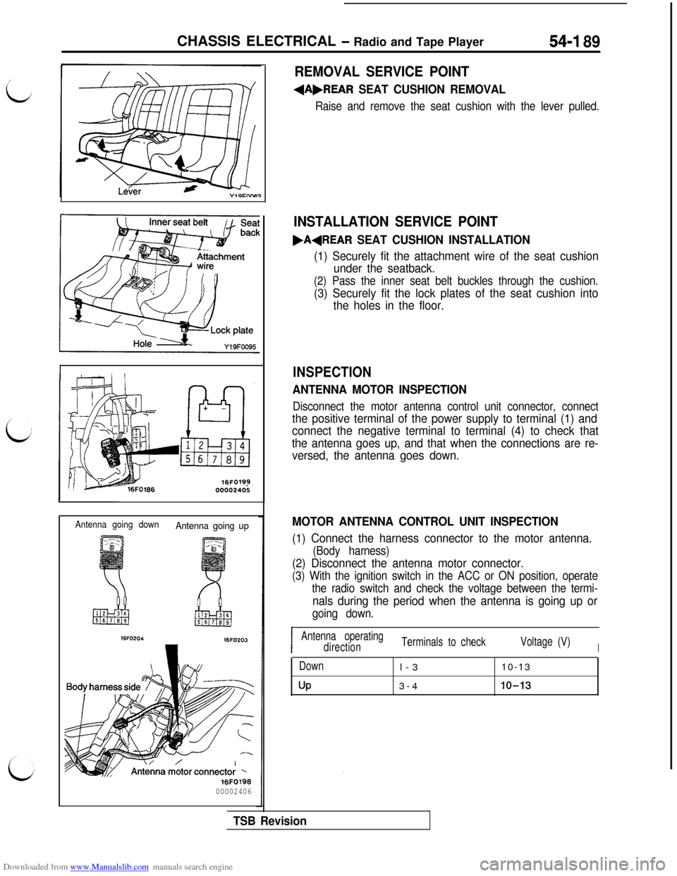
Antenna going downAntenna going up
16FO203
16F019800002406
REMOVAL SERVICE POINT
+A,REAR SEAT CUSHION REMOVAL
Raise and remove the seat cushion with the lever pulled.
INSTALLATION SERVICE POINT
.AqREAR SEAT CUSHION INSTALLATION
(1) Securely fit the attachment wire of the seat cushion
under the seatback.
(2) Pass the inner seat belt buckles through the cushion.
(3) Securely fit the lock plates of the seat cushion into
the holes in the floor.
INSPECTION
ANTENNA MOTOR INSPECTION
Disconnect the motor antenna control unit connector, connect
the positive terminal of the power supply to terminal (1) and
connect the negative terminal to terminal (4) to check that
the antenna goes up, and that when the connections are re-
versed, the antenna goes down.
MOTOR ANTENNA CONTROL UNIT INSPECTION
(1) Connect the harness connector to the motor antenna.
(Body harness)
(2) Disconnect the antenna motor connector.
(3) With the ignition switch in the ACC or ON position, operate
the radio switch and check the voltage between the termi-
nals during the period when the antenna is going up or
going down.
I
I
Antenna operating
directionTerminals to checkVoltage (V)
I
Down
UPl-310-13
3-410-13
TSB Revision
Page 690 of 738
Downloaded from www.Manualslib.com manuals search engine 54-194CHASSIS ELECTRICAL - Rear Window Defogger
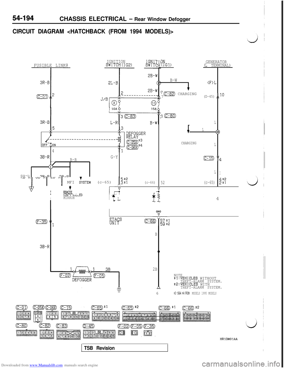
CIRCUIT DIAGRAM
FUSIBLE LINK@IGNITIONSWITCH(IG2)IGNIlSWIT(
I1 1OAb15A
3R-BI
,,5,,3/\,\
imGER------_____---______--~~~~~
OFF-,=ON
'4
3B-R
B-RG-Y
J(1,
pa-u7?a-D'3u-0
.y "I u" "I =" :‘I MFI &STEM (c-65) I,"::(c-66)
vI
t
%!E, i Cl?L-7r
IbUI” I KUl2~C”MIRRORI4 I7i7-
IN(IGl)GENERATOR(L TERMINAL)
B-W
(F>L
7m CHARGING7(D-45)JO
3m
L
L
16s)
CHARGINGL
(c-15) :$
LI
52(c-65)2%4
GNO
EWc&+;;;
B
3B-R0
2B
NOTEal:VEHICLES WITHOUTTHEFT-ALARM SYSTEM.X2:VEHICLES WITHnTHEFT-ALARM SYSTEM.6
:3:1994 :4:FROMMODELS 1995 MODELS
HR13MOlAA
TSB Revision
Page 692 of 738
Downloaded from www.Manualslib.com manuals search engine 54-196CHASSIS ELECTRICAL - Rear Window Defogger
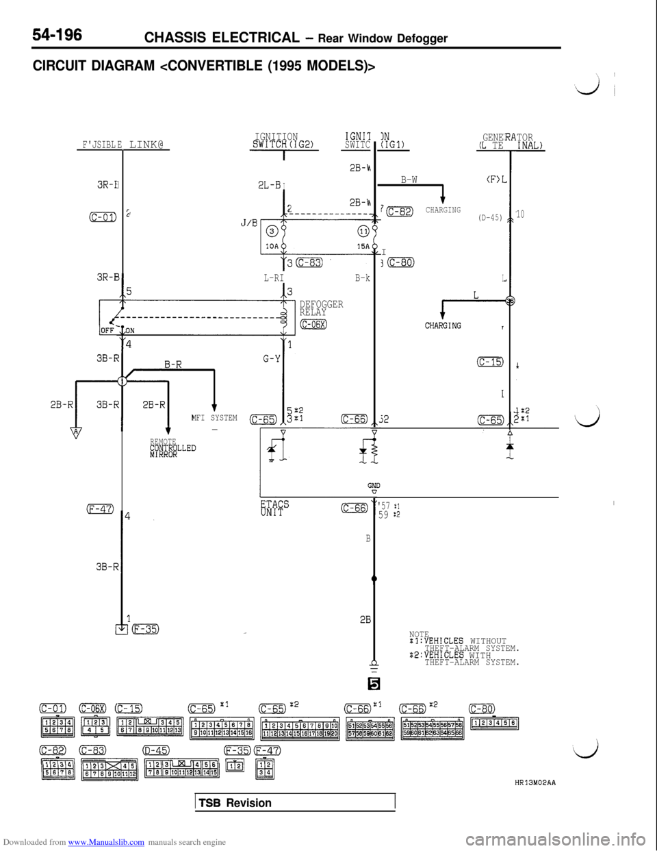
CIRCUIT DIAGRAM
F'JSIBLELINK@
3R-I3
(c-01)22B-h,-----------___.
3R-E
3B-F
38-F
IGNITIONIGNIlSWITCH(IG2)SWITC
- -
2L-BI
28-h
J’Bp
L-RIB-k
DEFOGGER
RELAY
(c-06x)
MFI SYSTEM3;:(c-66)-
REMOTE#JJ&LLED
GNIn
B
!B
INGENE(IGl)(L TE
B-W(F>I
7mCHARGINGI(D-45)
30
I
e-CHARGINGT
(c-15)
52
TORINAL)
10
'57 :1I
59 $2
NOTE:l:VEHICLES WITHOUTTHEFT-ALARM SYSTEM.22:VEHICLES WITHTHEFT-ALARM SYSTEM.
HR13M02AA
1 TSB Revision
Page 694 of 738
Downloaded from www.Manualslib.com manuals search engine 54-I 98CHASSIS ELECTRICAL - Rear Window Defogger
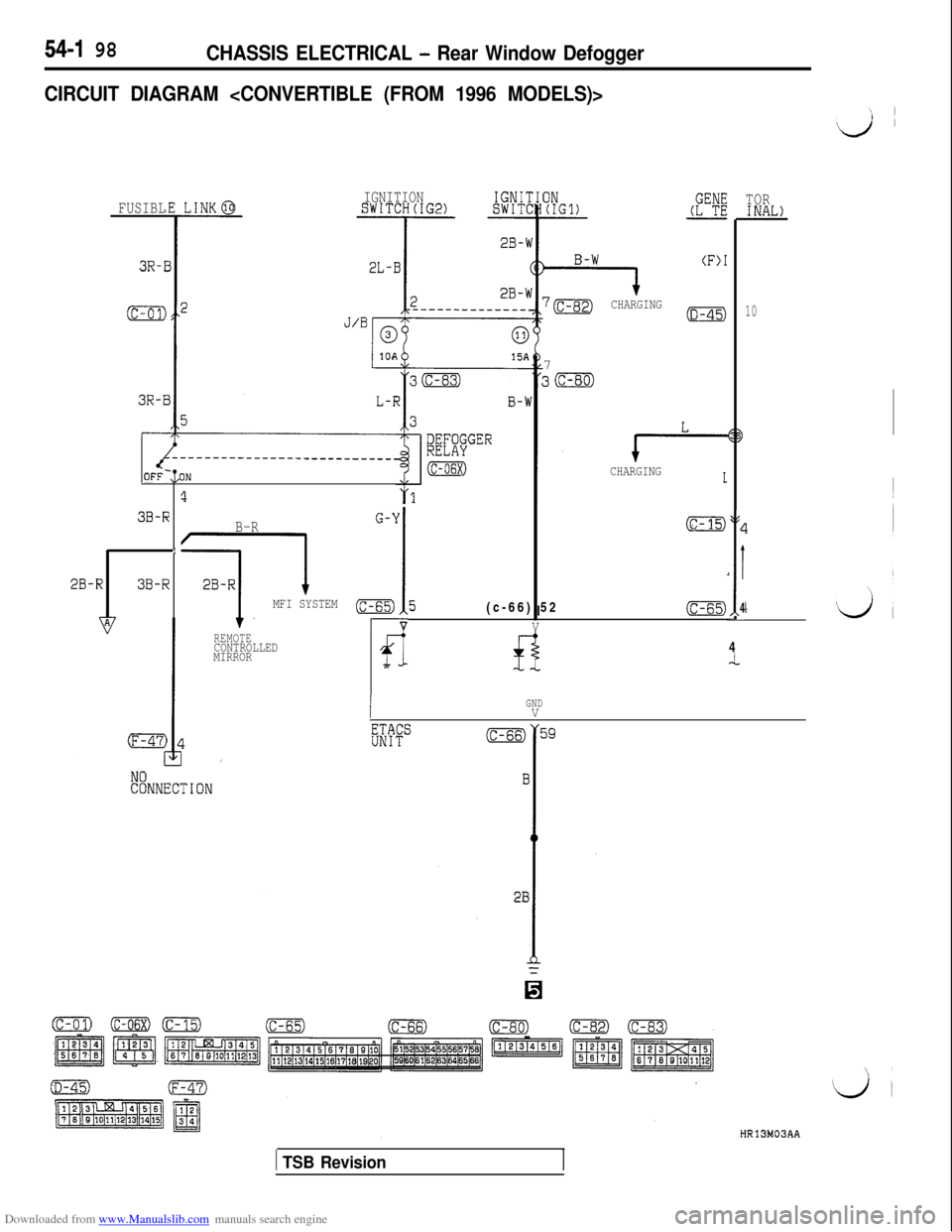
CIRCUIT DIAGRAM
2B-RFUSIBL
3R-I
(c-01)
3R-i
3B-R
1
3B-R
IGNITIONSWITCH(IG2)IGNIIISWITC
J’Bn
?
B-R
MFI SYSTEM
REMOTECONTROLLED
MIRROR
OFF-:,ON
-l (F)*
7BCHARGING7(D-45)
e-CHARGINGI
G-Y
,I I
(6-15)
(c-65)5(c-66) 52(c-65)
VV
fl
IGNDV
I
L
,I
4-4
TORINAL)
10
HR13M03AA
1 TSB Revision
Page 696 of 738
Downloaded from www.Manualslib.com manuals search engine 54-200CHASSIS ELECTRICAL - Rear Window Defogger
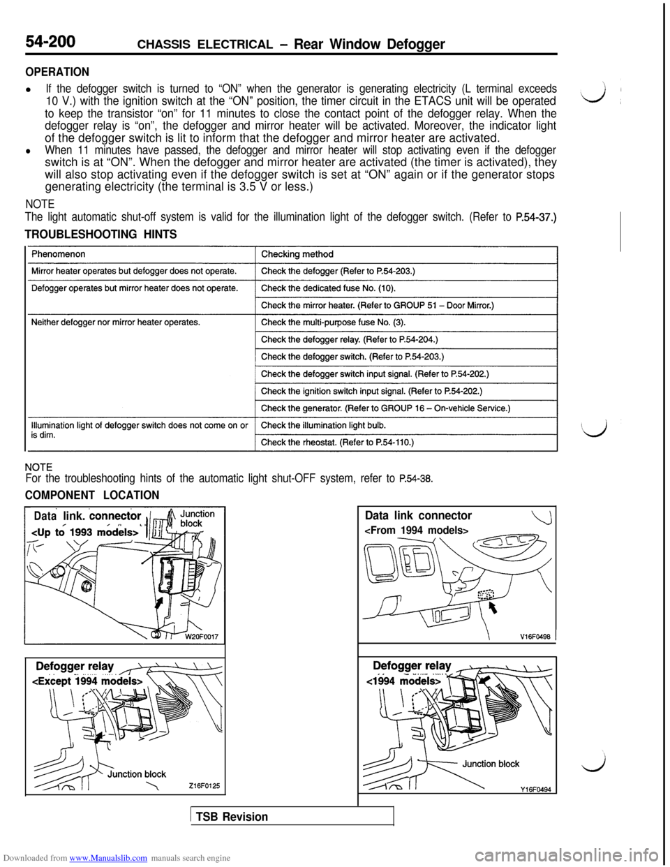
OPERATIONl
If the defogger switch is turned to “ON” when the generator is generating electricity (L terminal exceeds
10 V.) with the ignition switch at the “ON” position, the timer circuit in the ETACS unit will be operated
to keep the transistor “on” for 11 minutes to close the contact point of the defogger relay. When the
defogger relay is “on”,the defogger and mirror heater will be activated. Moreover, the indicator lightof the defogger switch is lit to inform that the defogger and mirror heater are activated.
lWhen 11 minutes have passed, the defogger and mirror heater will stop activating even if the defoggerswitch is at “ON”. When the defogger and mirror heater are activated (the timer is activated), they
will also stop activating even if the defogger switch is set at “ON” again or if the generator stops
generating electricity (the terminal is 3.5 V or less.)
NOTE
The light automatic shut-off system is valid for the illumination light of the defogger switch. (Refer to
P.54-37.)
TROUBLESHOOTING HINTS
NOTE
For the troubleshooting hints of the automatic light shut-OFF system, refer to P.54-38.
COMPONENT LOCATION
Datalink. connector
216FO125
Data link connector
\V16FO496 1
es.-‘) blocky,6Fww
1 TSB Revision
Page 698 of 738
Downloaded from www.Manualslib.com manuals search engine 54-202CHASSIS ELECTRICAL - Rear Window Defogger
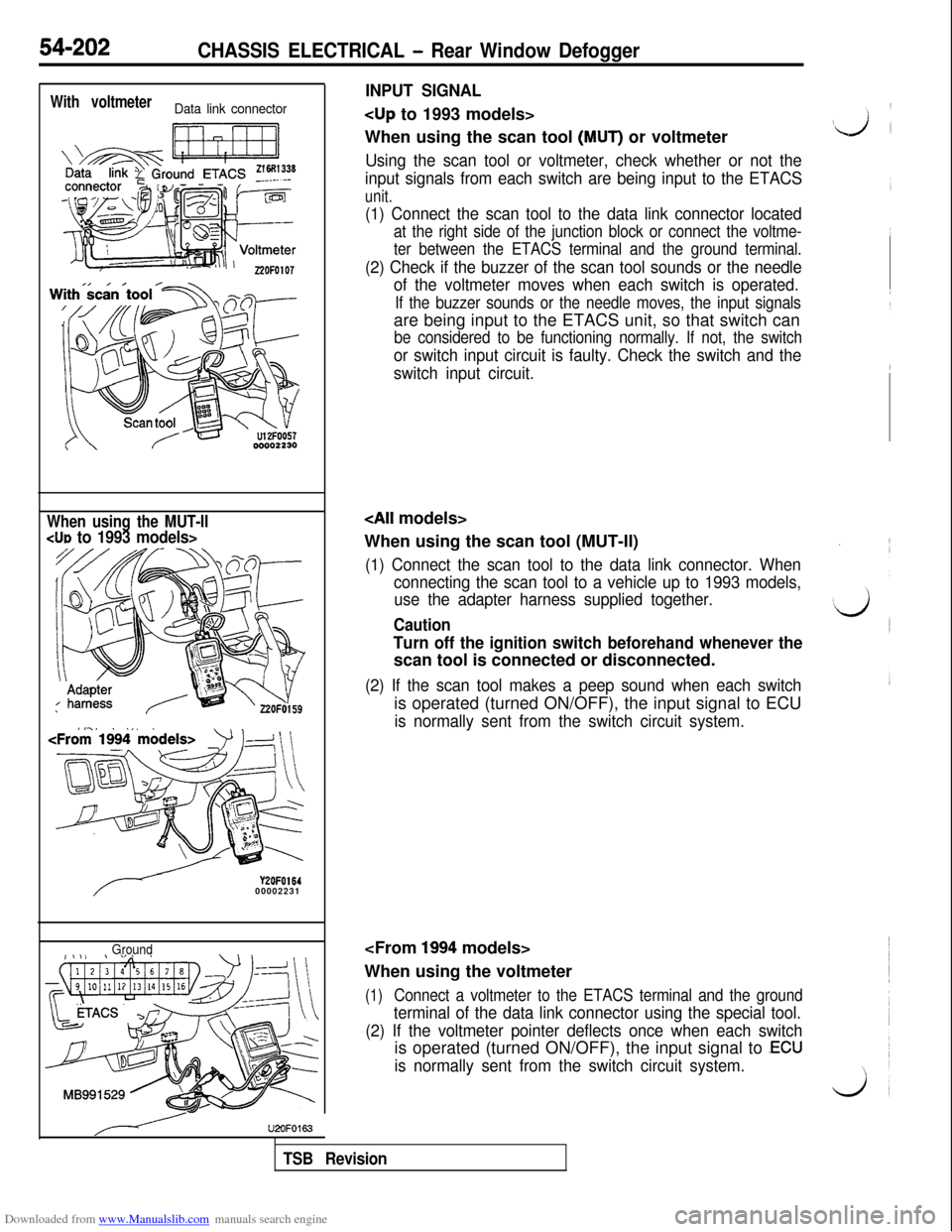
With voltmeterData link connector
When using the MUT-IICUD to 1993 models>
Y2OFO16400002231
Ground
INPUT SIGNAL
When using the scan tool
(MUT) or voltmeter
Using the scan tool or voltmeter, check whether or not the
input signals from each switch are being input to the ETACS
unit.
(1) Connect the scan tool to the data link connector located
at the right side of the junction block or connect the voltme-
ter between the ETACS terminal and the ground terminal.
(2) Check if the buzzer of the scan tool sounds or the needle
of the voltmeter moves when each switch is operated.
If the buzzer sounds or the needle moves, the input signalsare being input to the ETACS unit, so that switch can
be considered to be functioning normally. If not, the switch
or switch input circuit is faulty. Check the switch and the
switch input circuit.
When using the scan tool (MUT-II)
(1) Connect the scan tool to the data link connector. When
connecting the scan tool to a vehicle up to 1993 models,
use the adapter harness supplied together.
Caution
Turn off the ignition switch beforehand whenever thescan tool is connected or disconnected.
(2) If the scan tool makes a peep sound when each switchis operated (turned ON/OFF), the input signal to ECU
is normally sent from the switch circuit system.
When using the voltmeter
(1)Connect a voltmeter to the ETACS terminal and the ground
terminal of the data link connector using the special tool.
(2) If the voltmeter pointer deflects once when each switchis operated (turned ON/OFF), the input signal to
.ECU
is normally sent from the switch circuit system.
U2OFO163
TSB Revision
Page 702 of 738
Downloaded from www.Manualslib.com manuals search engine CHASSIS ELECTRICAL - Theft-alarm Svstem
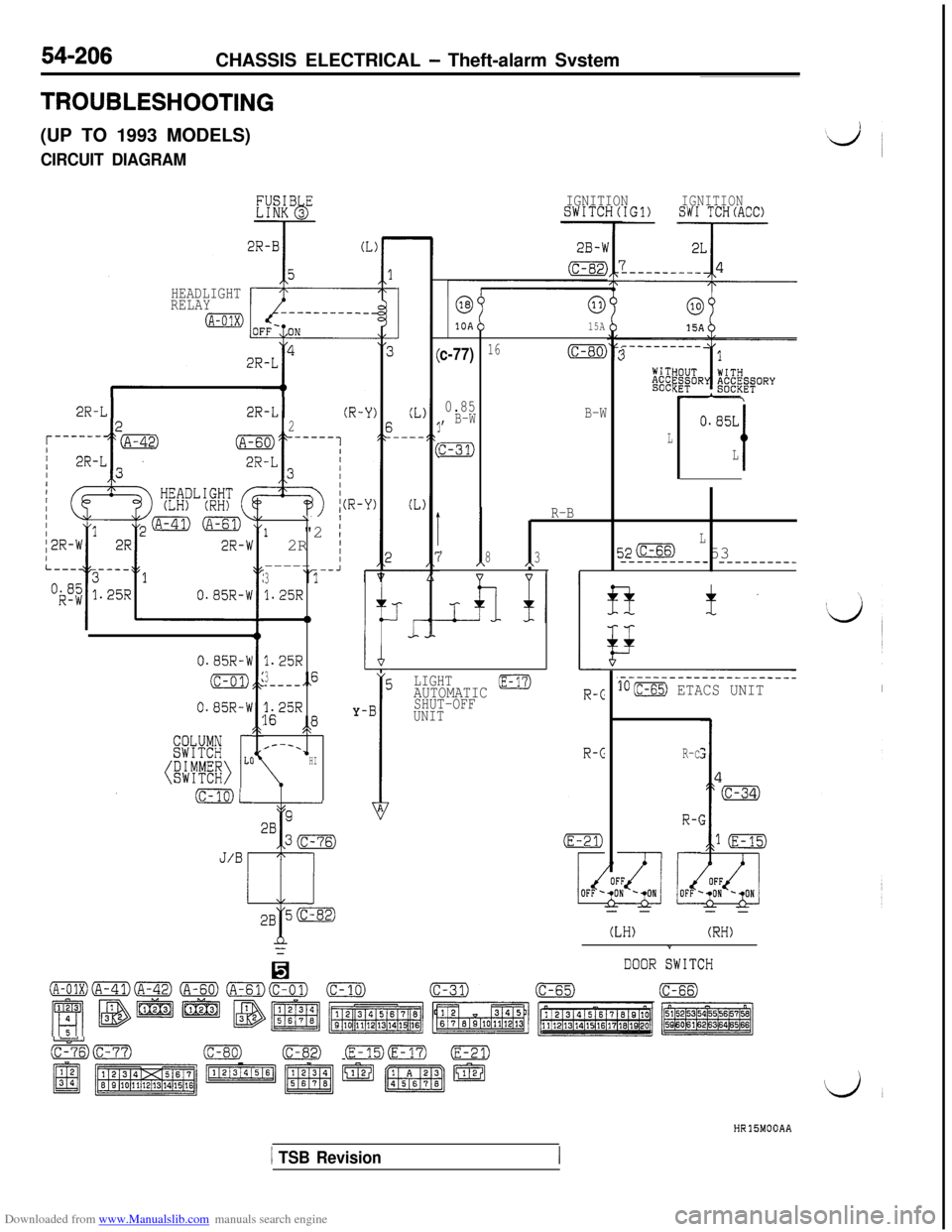
TROUBLESHOOTING(UP TO 1993 MODELS)
CIRCUIT DIAGRAM
HEADLIGHT
RELAY
0---------_
IGNITIONIGNITIONSWITCH(IG1)SW1 TCH(ACC)
63
10A
0
15A
c-77)16(c-80)
0.85, B-W
FJ$
B-W
----------1
xSOCI
0.85L
L
Lt
2R-L12R-L1(R.2
’ I
R-B
L
8
3520 53,\---------__ --------__
\II
1"2 /2R ;I----- --A3‘3
1.25R
0
1.25R
3_----,,6
1625R,8,C
I---.*HI
Y
+
LI
E
-B
1A
0.85R-W
(c-01)
0.85R-W
jLIGHTAUTOMATIC 0SHUT-OFF
UNIT
.----------------------
lO(c-65) ETACS UNITI
- -
E54#
G#~O L[r
R-c
R-c
nr-
- -
(LH)(RH)
DOOR TWITCH
;zk77)(c-80)(c-82) (E-15)(m) (E-21)
gj 1~~~~~~~~~
HR15MOOAA
1 TSB Revision
Page 704 of 738
Downloaded from www.Manualslib.com manuals search engine 54-208CHASSIS ELECTRICAL - Theft-alarm System
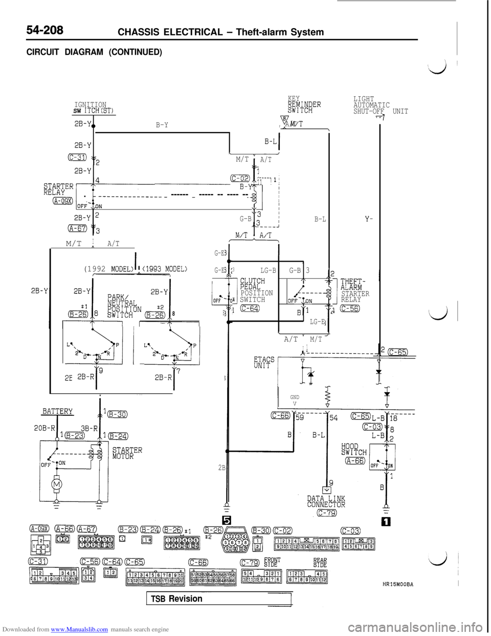
CIRCUIT DIAGRAM (CONTINUED)
LIGHT
AUTOMATIC
SHUT-OFF UNIT IGNITIONKEY
SW ITCH(ST)I#$!;'"
2B-Y0B-YyM/TA/T,
2B-Y
(c-31) v2LM/T "
t
A/T
2B-Y
,4may1j---1 1 j
L.mI.b ------____--___ - ------ - ----- -- ---- --$V??ER/
r77
OFi-,,ON/I\,/
2B-Y 2\G-B
(A-67) 2(3,J---_II ,-rn /TIM/T *A/Ta
I
G-E3
(1992 MODEL> *cl993 MODEL>
t
G-Er\3 ;
,
3LG-BG-B 3I
SE"
/\
POSITIONN SWITCHOFF-,:ONl(c-64)
6'1
LG-E
B-LY-
\A/T *
I
M/T
1
I
xm-STARTER
RELAY
l(c-56)t8E
L-2%13q 1 ‘-:liq2E
GNDV
2B
HR15MOOBAI
TSB Revision
Page 706 of 738
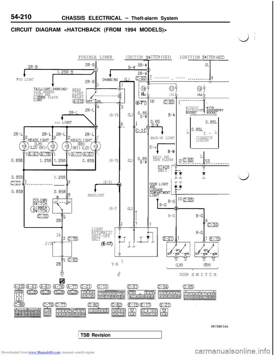
Downloaded from www.Manualslib.com manuals search engine 54-210CHASSIS ELECTRICAL - Theft-alarm System
CIRCUIT DIAGRAM
FUSIBLE LINK@IGNITIONI
2B-
(I
(
L)
3,t
Q
2)(I
@
i10
c-7’
Ob”
I
x
ObS
AAL,
D
'G0
DZ8
t
z
5
1
'ITCH(IG1)IGNITION SWITCH(ACC)
7_ ------ - ---- Tjj-
-l
0
15A@
15A
2R-B
FOG LIGHT
5TAILLIGHT.bARKING/
SIDE MARKER
LIGHT AND
b;gXySE PLATE
HEAD
LIGHT
RELAY
(A-O1X)16 (c-80)------____3
1
1
WITHOUTWITHACCESSORY ACCESS
SoCKET
0.85L
L 0.85LI--L
CIGARETTE
LIGHTER
\
>)
I
(R-Y‘3D-r2R-L;ORY
B-h
----IBACK-UP LIGHT
3-w
1B-W
RADIO ANDTAPE PLAYER
rFOG
LIGHT
3
>
1
(R-Y
0.85BI
@” L1GHTJGGAGEiyi;tRTMENT
(c-ol)&---------- ____ ,F
0.85B0.85R
* e8
2B,,3 (c-76)J/B'
A
\/ _
3 (c-82)28
n=
(R-Y)
HEADLIGHT
lO(c-65)
(R-Y(I
R-G
I8
Vk
i
LIGHT
AUTOMATIC
SHUT-OFF
UNIT
- -- -= =
(LH)(RH)\*/
DOORSWITCH
2hJ
5(E-17)._i
Y-B56
A
HRlJMOlAA
1 TSB Revision