diagram MITSUBISHI 380 2005 Owners Manual
[x] Cancel search | Manufacturer: MITSUBISHI, Model Year: 2005, Model line: 380, Model: MITSUBISHI 380 2005Pages: 1500, PDF Size: 47.87 MB
Page 446 of 1500
INPUT SIGNAL PROCEDURES
SIMPLIFIED WIRING SYSTEM (SWS)54B-446
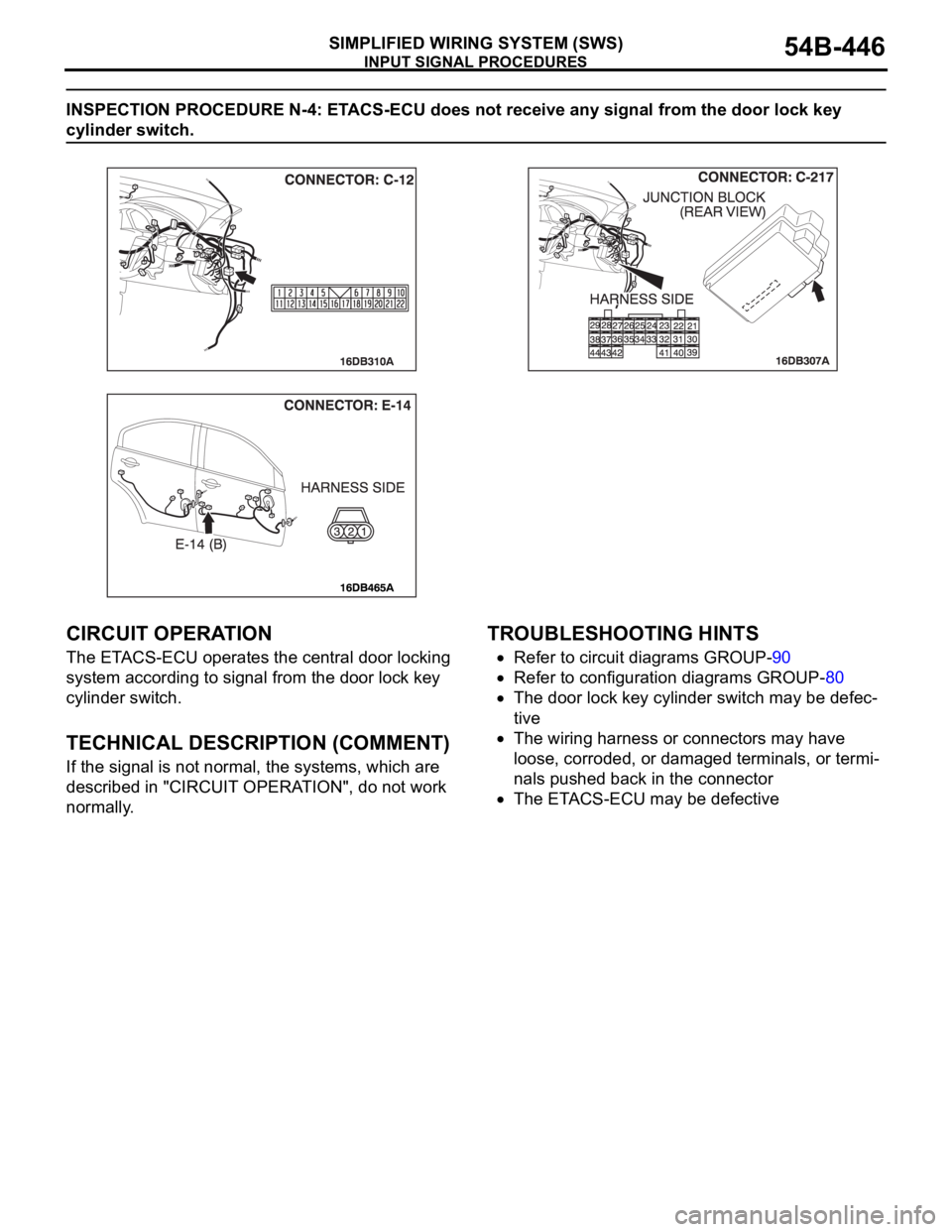
INSPECTION PROCEDURE N-4: ETACS-ECU does not receive any signal from the door lock key
cylinder switch.
.
CIRCUIT OPERATION
The ETACS-ECU operates the central door locking
system according to signal from the door lock key
cylinder switch.
.
TECHNICAL DESCRIPTION (COMMENT)
If the signal is not normal, the systems, which are
described in "CIRCUIT OPERATION", do not work
normally.
.
TROUBLESHOOTING HINTS
Refer to circuit diagrams GROUP-90
Refer to configuration diagrams GROUP-80
The door lock key cylinder switch may be defec-
tive
The wiring harness or connectors may have
loose, corroded, or damaged terminals, or termi-
nals pushed back in the connector
The ETACS-ECU may be defective
Page 451 of 1500
INPUT SIGNAL PROCEDURES
SIMPLIFIED WIRING SYSTEM (SWS)54B-451
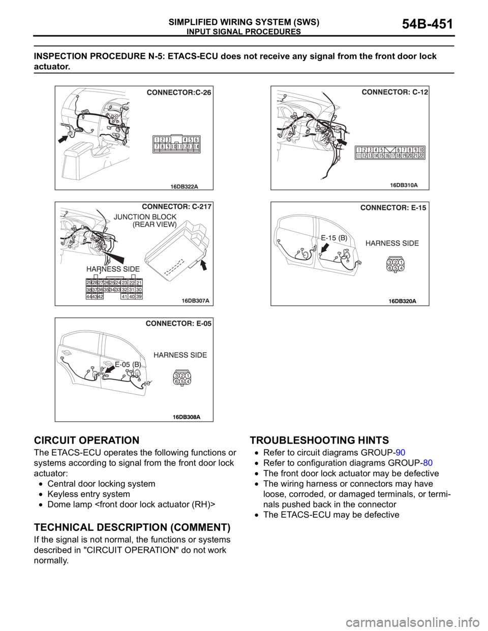
INSPECTION PROCEDURE N-5: ETACS-ECU does not receive any signal from the front door lock
actuator.
.
CIRCUIT OPERATION
The ETACS-ECU operates the following functions or
systems according to signal from the front door lock
actuator:
Central door locking system
Keyless entry system
Dome lamp
.
TECHNICAL DESCRIPTION (COMMENT)
If the signal is not normal, the functions or systems
described in "CIRCUIT OPERATION" do not work
normally.
.
TROUBLESHOOTING HINTS
Refer to circuit diagrams GROUP-90
Refer to configuration diagrams GROUP-80
The front door lock actuator may be defective
The wiring harness or connectors may have
loose, corroded, or damaged terminals, or termi-
nals pushed back in the connector
The ETACS-ECU may be defective
Page 460 of 1500
INPUT SIGNAL PROCEDURES
SIMPLIFIED WIRING SYSTEM (SWS)54B-460
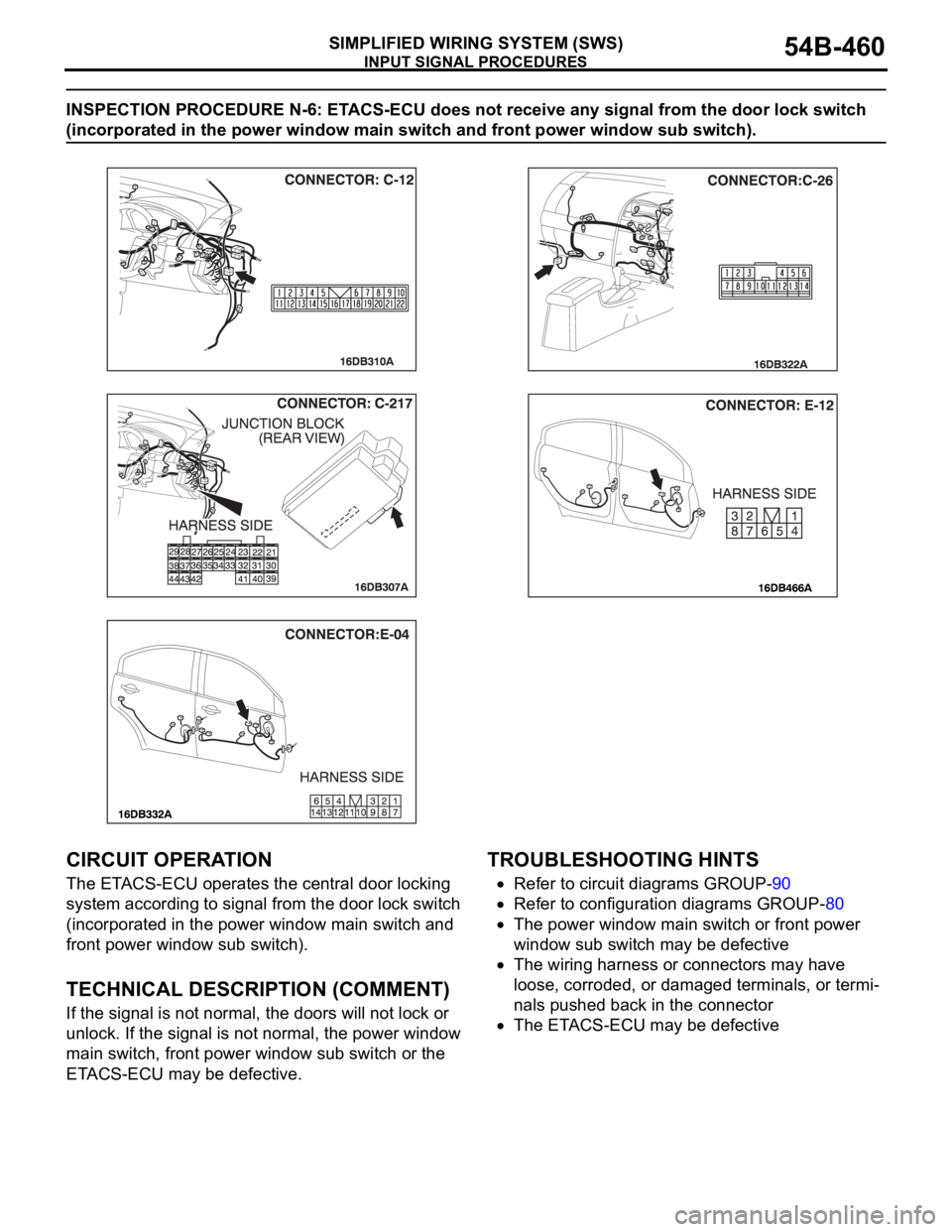
INSPECTION PROCEDURE N-6: ETACS-ECU does not receive any signal from the door lock switch
(incorporated in the power window main switch and front power window sub switch).
.
CIRCUIT OPERATION
The ETACS-ECU operates the central door locking
system according to signal from the door lock switch
(incorporated in the power window main switch and
front power window sub switch).
.
TECHNICAL DESCRIPTION (COMMENT)
If the signal is not normal, the doors will not lock or
unlock. If the signal is not normal, the power window
main switch, front power window sub switch or the
ETACS-ECU may be defective.
.
TROUBLESHOOTING HINTS
Refer to circuit diagrams GROUP-90
Refer to configuration diagrams GROUP-80
The power window main switch or front power
window sub switch may be defective
The wiring harness or connectors may have
loose, corroded, or damaged terminals, or termi-
nals pushed back in the connector
The ETACS-ECU may be defective
Page 469 of 1500
INPUT SIGNAL PROCEDURES
SIMPLIFIED WIRING SYSTEM (SWS)54B-469
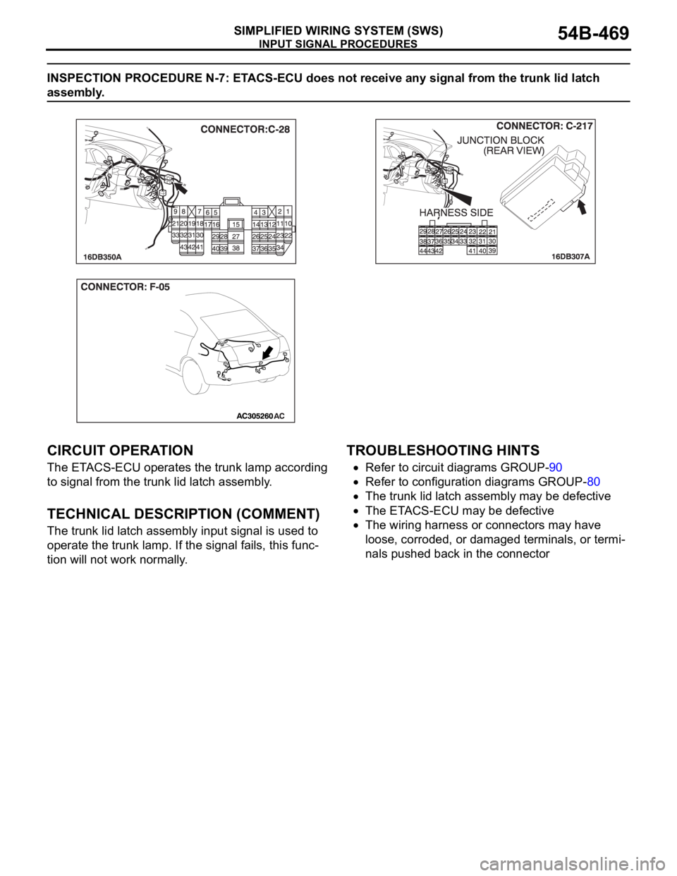
INSPECTION PROCEDURE N-7: ETACS-ECU does not receive any signal from the trunk lid latch
assembly.
.
CIRCUIT OPERATION
The ETACS-ECU operates the trunk lamp according
to signal from the trunk lid latch assembly.
.
TECHNICAL DESCRIPTION (COMMENT)
The trunk lid latch assembly input signal is used to
operate the trunk lamp. If the signal fails, this func-
tion will not work normally.
.
TROUBLESHOOTING HINTS
Refer to circuit diagrams GROUP-90
Refer to configuration diagrams GROUP-80
The trunk lid latch assembly may be defective
The ETACS-ECU may be defective
The wiring harness or connectors may have
loose, corroded, or damaged terminals, or termi-
nals pushed back in the connector
Page 472 of 1500
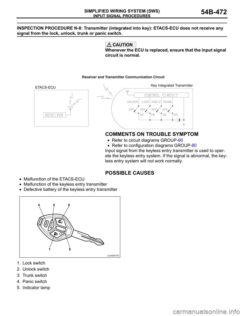
INPUT SIGNAL PROCEDURES
SIMPLIFIED WIRING SYSTEM (SWS)54B-472
INSPECTION PROCEDURE N-8: Transmitter (integrated into key): ETACS-ECU does not receive any
signal from the lock, unlock, trunk or panic switch.
Whenever the ECU is replaced, ensure that the input signal
circuit is normal.
.
COMMENTS ON TROUBLE SYMPTOM
Refer to circuit diagrams GROUP-90
Refer to configuration diagrams GROUP-80
Input signal from the keyless entry transmitter is used to oper-
ate the keyless entry system. If the signal is abnormal, the key-
less entry system will not work normally.
.
POSSIBLE CAUSES
Malfunction of the ETACS-ECU
Malfunction of the keyless entry transmitter
Defective battery of the keyless entry transmitter
1. Lock switch
2. Unlock switch
3. Trunk switch
4. Panic switch
5. Indicator lamp
Page 474 of 1500
INPUT SIGNAL PROCEDURES
SIMPLIFIED WIRING SYSTEM (SWS)54B-474
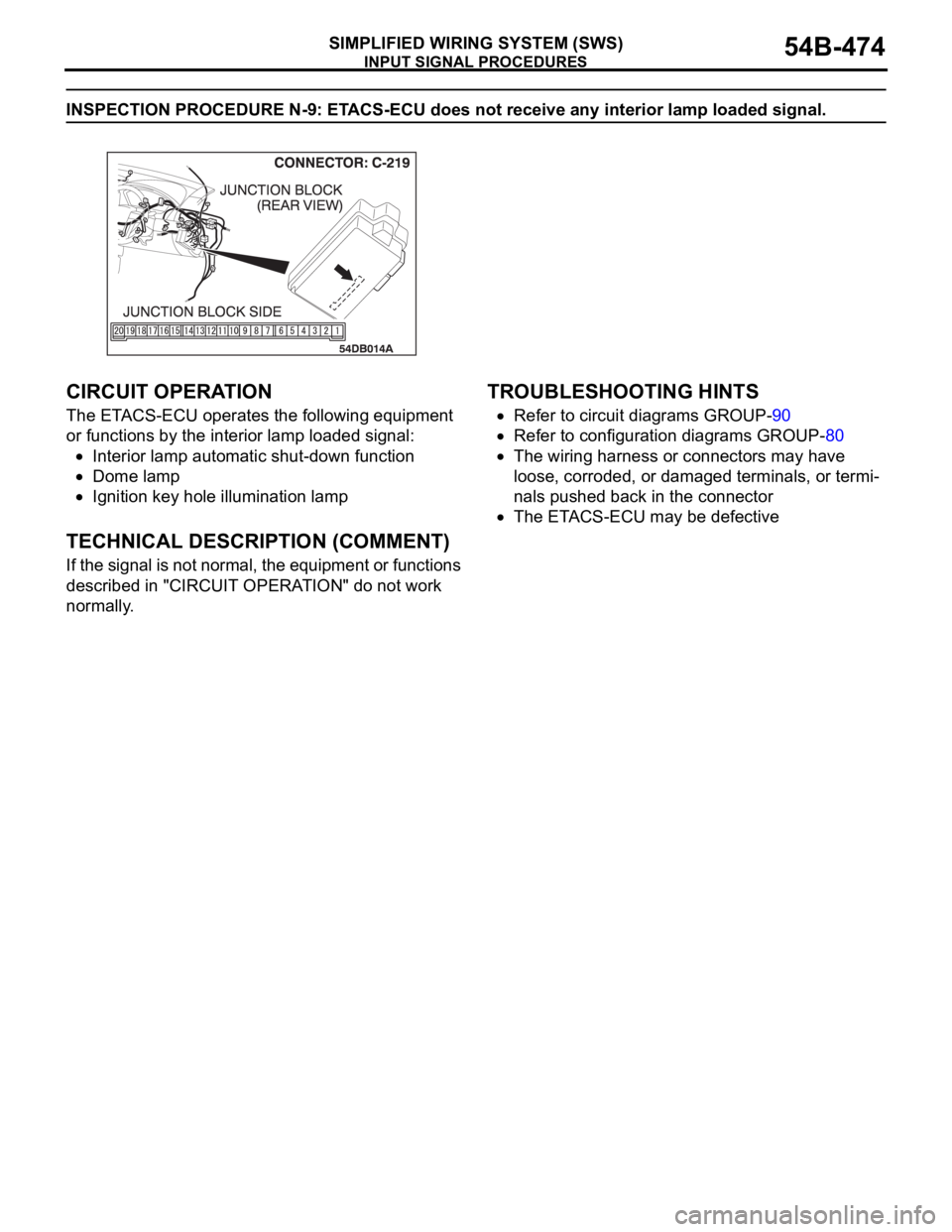
INSPECTION PROCEDURE N-9: ETACS-ECU does not receive any interior lamp loaded signal.
.
CIRCUIT OPERATION
The ETACS-ECU operates the following equipment
or functions by the interior lamp loaded signal:
Interior lamp automatic shut-down function
Dome lamp
Ignition key hole illumination lamp
.
TECHNICAL DESCRIPTION (COMMENT)
If the signal is not normal, the equipment or functions
described in "CIRCUIT OPERATION" do not work
normally.
.
TROUBLESHOOTING HINTS
Refer to circuit diagrams GROUP-90
Refer to configuration diagrams GROUP-80
The wiring harness or connectors may have
loose, corroded, or damaged terminals, or termi-
nals pushed back in the connector
The ETACS-ECU may be defective
Page 512 of 1500

FRONT SEAT ASSEMBLY
INTERIOR52A-23
INSPECTIONM1522005500113
POWER SEAT CONTINUITY AND DIAGNOSIS
CHECK
SPECIAL TOOL:
MB991219: Inspection Test Harness
CIRCUIT DIAGRAMS:
Refer to circuit diagrams GROUP-90
Refer to configuration diagrams GROUP-80
NOTE: Check connectors and terminals for damage or
loose connections at the seat harness and all supply
circuits connections to seat. Repair or replace wiring
harness if damaged.
NON-MEMORY SEAT DIAGNOSIS
POWER SEAT SUPPLY AND GROUND CONNECTOR (D-40)
NOTE: The special tool (Inspection test harness) MB991219
for connector pin contact pressure should be used. The test
probe should never be forcibly inserted, as it may cause a
defective contact.
4-WAY TRACK (NON MEMORY)
NOTE: The special tool (Inspection test harness) MB991219
for connector pin contact pressure should be used. The test
probe should never be forcibly inserted, as it may cause a
defective contact. SUPPLY TEST
CONNECTION
(D-40) SPECIFIED CONDITION
BATTERY
SUPPLY112V
GROUND 2 Less than 2 ohms or 0V
SWITCH POSITION TEST CONNECTION SPECIFIED CONDITION
SWITCH MOTOR
REAR LIFT MOTOR UP 1 1 Less than 2 ohms
DOWN 4 5 Less than 2 ohms
FRONT LIFT MOTOR UP 2 1 Less than 2 ohms
DOWN 3 5 Less than 2 ohms
Page 514 of 1500

FRONT SEAT ASSEMBLY
INTERIOR52A-25
MEMORY SEAT DIAGNOSIS
POWER SEAT SUPPLY AND GROUND CONNECTOR (D-40)
SPECIAL TOOL:
MB991219: Inspection Test Harness
CIRCUIT DIAGRAMS:
Refer to circuit diagrams GROUP-90
Refer to configuration diagrams GROUP-80
NOTE: Check connectors and terminals for damage or
loose connections at the seat harness and all supply
circuits connections to seat. Repair or replace wiring
harness if damaged.
NOTE: The special tool (Inspection test harness) MB991219
for connector pin contact pressure should be used. The test
probe should never be forcibly inserted, as it may cause a
defective contact.
10-WAY TRACK (MEMORY)- SOURCE TO (MSC) POWER
CONNECTOR (D-38)
NOTE: The special tool (Inspection test harness) MB991219
for connector pin contact pressure should be used. The test
probe should never be forcibly inserted, as it may cause a
defective contact. SUPPLY TEST
CONNECTION
(D-40) SPECIFIED CONDITION
BATTERY
SUPPLY112V
GROUND 2 Less than 2 ohms or 0V
CIRCUIT
DESCRIPTION TEST CONNECTION
(MSC)
POWER
(D-38) SOURCE INTERMEDIATE
CONNECTOR
GROUND 1 GROUND 15 -
"NEUTRAL" 2 A/T-ECU (B-19) 31 (B-25) pin 9
Bus LT 3 - -
IGNITION- LED ON 4 (IGN 2) J/B fuse 9 (C-28) pin 35
DOOR SW.- LED ON 5 RH Door sw. (D-34) 2 -
VEHICLE SPEED 6 A/T-ECU (B-19) 24 (C-25) pin 8
"PARK" 7 A/T-ECU (B-19) 30 (C-25) pin 10
N.C - - -
Page 515 of 1500

FRONT SEAT ASSEMBLY
INTERIOR52A-26
10-WAY TRACK (MEMORY)-switch to module- 20 pin
CIRCUIT DIAGRAMS:
Refer to circuit diagrams GROUP-90
Refer to configuration diagrams GROUP-80
NOTE: Check connectors and terminals for damage or
loose connections at the seat harness and all supply
circuits connections to seat. Repair or replace wiring
harness if damaged.
NOTE: The special tool (Inspection test harness) MB991219
for connector pin contact pressure should be used. The test
probe should never be forcibly inserted, as it may cause a
defective contact.
10-WAY TRACK (MEMORY) 12pin connector (A) at module
to motor circuits
NOTE: The special tool (Inspection test harness) MB991219
for connector pin contact pressure should be used. The test
probe should never be forcibly inserted, as it may cause a
defective contact. SWITCH POSITION TEST CONNECTION SPECIFIED CONDITION
SWITCH (MSC)
MODULE
20 PIN
REAR LIFT MOTOR UP 7 16 Less than 2 ohms
DOWN 8 13 Less than 2 ohms
FRONT LIFT MOTOR UP 6 5 Less than 2 ohms
DOWN 9 7 Less than 2 ohms
TRACK/ SLIDE MOTOR FORWARD 10 4 Less than 2 ohms
BACK 3 3 Less than 2 ohms
RECLINING MOTOR FORWARD 4 14 Less than 2 ohms
BACK 2 2 Less than 2 ohms
SWITCH POSITION TEST CONNECTION SPECIFIED CONDITION
(MSC)
MODULE
12 PIN(A) MOTOR
REAR LIFT MOTOR UP 2 1 Less than 2 ohms
DOWN 3 5 Less than 2 ohms
FRONT LIFT MOTOR UP 11 5 Less than 2 ohms
DOWN 10 1 Less than 2 ohms
TRACK/ SLIDE MOTOR FORWARD 4 2 Less than 2 ohms
BACK 9 1 Less than 2 ohms
Page 516 of 1500

FRONT SEAT ASSEMBLY
INTERIOR52A-27
10-WAY TRACK (MEMORY) lumbar switch to module
(20-pin)
CIRCUIT DIAGRAMS:
Refer to circuit diagrams GROUP-90
Refer to configuration diagrams GROUP-80
NOTE: Check connectors and terminals for damage or
loose connections at the seat harness and all supply
circuits connections to seat. Repair or replace wiring
harness if damaged.
NOTE: The special tool (Inspection test harness) MB991219
for connector pin contact pressure should be used. The test
probe should never be forcibly inserted, as it may cause a
defective contact.
10-WAY TRACK (MEMORY) lumbar and recline module
connector (12-pin) to motors
NOTE: The special tool (Inspection test harness) MB991219
for connector pin contact pressure should be used. The test
probe should never be forcibly inserted, as it may cause a
defective contact. SWITCH POSITION TEST CONNECTION SPECIFIED CONDITION
SWITCH (MSC)
MODULE
LUMBAR SWITCH SOFTER 2 12 (20pin) Less than 2 ohms
HARDER 4 6 (20pin) Less than 2 ohms
MEMORY 3 6 (16pin) Less than 2 ohms
SWITCH POSITION TEST CONNECTION SPECIFIED CONDITION
(MSC)
MODULE
12 PIN MOTOR
LUMBAR MOTOR SOFTER 7 1 Less than 2 ohms
HARDER 2 2 Less than 2 ohms
RECLINER MOTOR FORWARD 1 1 Less than 2 ohms
BACK 8 5 Less than 2 ohms