diagram MITSUBISHI 380 2005 Repair Manual
[x] Cancel search | Manufacturer: MITSUBISHI, Model Year: 2005, Model line: 380, Model: MITSUBISHI 380 2005Pages: 1500, PDF Size: 47.87 MB
Page 257 of 1500

SYMPTOM PROCEDURES
SIMPLIFIED WIRING SYSTEM (SWS)54B-257
HEADLAMP AND TAILLAMP
GENERAL DESCRIPTION CONCERNING THE HEADLAMPS AND TAILLAMPSM1549021300264
Refer to circuit diagrams GROUP-90
Refer to configuration diagrams GROUP-80The following ECUs affect the functions and control
of the headlamps and the taillamps.
FUNCTION CONTROL ECU
Taillamps Front-ECU, column switch
Headlamps ETACS-ECU, front-ECU, column switch
High-beam indicator lamp ETACS-ECU, column switch
Headlamp automatic-shutoff function ETACS-ECU, front-ECU, column switch
Dimmer automatic reset function Front-ECU, column switch
Page 260 of 1500
SYMPTOM PROCEDURES
SIMPLIFIED WIRING SYSTEM (SWS)54B-260
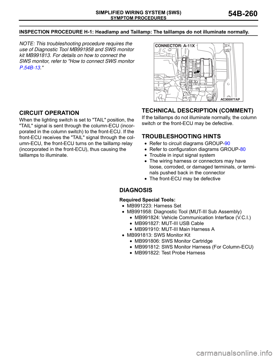
INSPECTION PROCEDURE H-1: Headlamp and Taillamp: The taillamps do not illuminate normally.
NOTE: This troubleshooting procedure requires the
use of Diagnostic Tool MB991958 and SWS monitor
kit MB991813. For details on how to connect the
SWS monitor, refer to "How to connect SWS monitor
P.54B-13."
.
CIRCUIT OPERATION
When the lighting switch is set to "TAIL" position, the
"TAIL" signal is sent through the column-ECU (incor-
porated in the column switch) to the front-ECU. If the
front-ECU receives the "TAIL" signal through the col-
umn-ECU, the front-ECU turns on the taillamp relay
(incorporated in the front-ECU), thus causing the
taillamps to illuminate.
.
TECHNICAL DESCRIPTION (COMMENT)
If the taillamps do not illuminate normally, the column
switch or the front-ECU may be defective.
.
TROUBLESHOOTING HINTS
Refer to circuit diagrams GROUP-90
Refer to configuration diagrams GROUP-80
Trouble in input signal system
The wiring harness or connectors may have
loose, corroded, or damaged terminals, or termi-
nals pushed back in the connector
The front-ECU may be defective
DIAGNOSIS
Required Special Tools:
MB991223: Harness Set
MB991958: Diagnostic Tool (MUT-III Sub Assembly)
MB991824: Vehicle Communication Interface (V.C.I.)
MB991827: MUT-III USB Cable
MB991910: MUT-III Main Harness A
MB991813: SWS Monitor Kit
MB991806: SWS Monitor Cartridge
MB991812: SWS Monitor Harness (For Column-ECU)
MB991822: Test Probe Harness
Page 264 of 1500
SYMPTOM PROCEDURES
SIMPLIFIED WIRING SYSTEM (SWS)54B-264
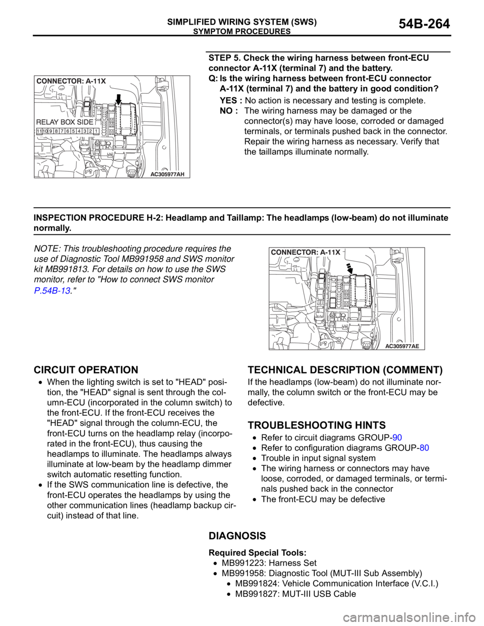
STEP 5. Check the wiring harness between front-ECU
connector A-11X (terminal 7) and the battery.
Q: Is the wiring harness between front-ECU connector
A-11X (terminal 7) and the battery in good condition?
YES : No action is necessary and testing is complete.
NO : The wiring harness may be damaged or the
connector(s) may have loose, corroded or damaged
terminals, or terminals pushed back in the connector.
Repair the wiring harness as necessary. Verify that
the taillamps illuminate normally.
INSPECTION PROCEDURE H-2: Headlamp and Taillamp: The headlamps (low-beam) do not illuminate
normally.
NOTE: This troubleshooting procedure requires the
use of Diagnostic Tool MB991958 and SWS monitor
kit MB991813. For details on how to use the SWS
monitor, refer to "How to connect SWS monitor
P.54B-13."
.
CIRCUIT OPERATION
When the lighting switch is set to "HEAD" posi-
tion, the "HEAD" signal is sent through the col-
umn-ECU (incorporated in the column switch) to
the front-ECU. If the front-ECU receives the
"HEAD" signal through the column-ECU, the
front-ECU turns on the headlamp relay (incorpo-
rated in the front-ECU), thus causing the
headlamps to illuminate. The headlamps always
illuminate at low-beam by the headlamp dimmer
switch automatic resetting function.
If the SWS communication line is defective, the
front-ECU operates the headlamps by using the
other communication lines (headlamp backup cir-
cuit) instead of that line.
.
TECHNICAL DESCRIPTION (COMMENT)
If the headlamps (low-beam) do not illuminate nor-
mally, the column switch or the front-ECU may be
defective.
.
TROUBLESHOOTING HINTS
Refer to circuit diagrams GROUP-90
Refer to configuration diagrams GROUP-80
Trouble in input signal system
The wiring harness or connectors may have
loose, corroded, or damaged terminals, or termi-
nals pushed back in the connector
The front-ECU may be defective
DIAGNOSIS
Required Special Tools:
MB991223: Harness Set
MB991958: Diagnostic Tool (MUT-III Sub Assembly)
MB991824: Vehicle Communication Interface (V.C.I.)
MB991827: MUT-III USB Cable
Page 268 of 1500
SYMPTOM PROCEDURES
SIMPLIFIED WIRING SYSTEM (SWS)54B-268
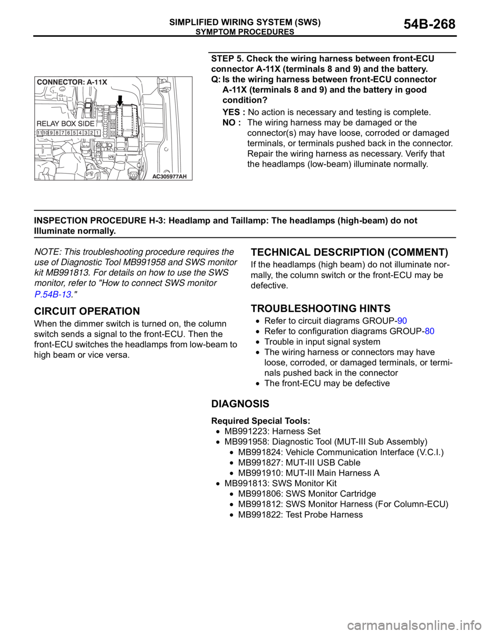
STEP 5. Check the wiring harness between front-ECU
connector A-11X (terminals 8 and 9) and the battery.
Q: Is the wiring harness between front-ECU connector
A-11X (terminals 8 and 9) and the battery in good
condition?
YES : No action is necessary and testing is complete.
NO : The wiring harness may be damaged or the
connector(s) may have loose, corroded or damaged
terminals, or terminals pushed back in the connector.
Repair the wiring harness as necessary. Verify that
the headlamps (low-beam) illuminate normally.
INSPECTION PROCEDURE H-3: Headlamp and Taillamp: The headlamps (high-beam) do not
Illuminate normally.
NOTE: This troubleshooting procedure requires the
use of Diagnostic Tool MB991958 and SWS monitor
kit MB991813. For details on how to use the SWS
monitor, refer to "How to connect SWS monitor
P.54B-13."
.
CIRCUIT OPERATION
When the dimmer switch is turned on, the column
switch sends a signal to the front-ECU. Then the
front-ECU switches the headlamps from low-beam to
high beam or vice versa.
.
TECHNICAL DESCRIPTION (COMMENT)
If the headlamps (high beam) do not illuminate nor-
mally, the column switch or the front-ECU may be
defective.
.
TROUBLESHOOTING HINTS
Refer to circuit diagrams GROUP-90
Refer to configuration diagrams GROUP-80
Trouble in input signal system
The wiring harness or connectors may have
loose, corroded, or damaged terminals, or termi-
nals pushed back in the connector
The front-ECU may be defective
DIAGNOSIS
Required Special Tools:
MB991223: Harness Set
MB991958: Diagnostic Tool (MUT-III Sub Assembly)
MB991824: Vehicle Communication Interface (V.C.I.)
MB991827: MUT-III USB Cable
MB991910: MUT-III Main Harness A
MB991813: SWS Monitor Kit
MB991806: SWS Monitor Cartridge
MB991812: SWS Monitor Harness (For Column-ECU)
MB991822: Test Probe Harness
Page 271 of 1500

SYMPTOM PROCEDURES
SIMPLIFIED WIRING SYSTEM (SWS)54B-271
INSPECTION PROCEDURE H-4: Headlamp and Taillamp: When the passing switch is turned "ON," the
headlamps (low-beam or high-beam) do not illuminate.
NOTE: This troubleshooting procedure requires the
use of Diagnostic Tool MB991958 and SWS monitor
kit MB991813. For details on how to use the SWS
monitor, refer to "How to connect SWS monitor
P.54B-13."
.
TECHNICAL DESCRIPTION (COMMENT)
If both of the headlamps (low-beam and high-beam)
do not illuminate, the input circuit from the passing
switch or the front-ECU may be defective.
.
TROUBLESHOOTING HINTS
Refer to circuit diagrams GROUP-90
Refer to configuration diagrams GROUP-80
Trouble in input signal system
The wiring harness or connectors may have
loose, corroded, or damaged terminals, or termi-
nals pushed back in the connector
The front-ECU may be defective
DIAGNOSIS
Required Special Tools:
MB991223: Harness Set
MB991958: Diagnostic Tool (MUT-III Sub Assembly)
MB991824: Vehicle Communication Interface (V.C.I.)
MB991827: MUT-III USB Cable
MB991910: MUT-III Main Harness A
MB991813: SWS Monitor Kit
MB991806: SWS Monitor Cartridge
MB991812: SWS Monitor Harness (For Column-ECU)
MB991822: Test Probe Harness
STEP 1. Check the headlamps.
Q: Do the headlamps (low-beam and high-beam) illuminate
normally?
The headlamps illuminate normally. : Go to Step 2.
Headlamps (low-beam) do not illuminate normally :
Refer to Inspection Procedure H-2 "The headlamps
(low-beam) do not illuminate normally P.54B-264.
Headlamps (high-beam) do not illuminate normally :
Refer to Inspection Procedure H-3 "The headlamps
(high-beam) do not illuminate normally P.54B-268.
Page 273 of 1500

SYMPTOM PROCEDURES
SIMPLIFIED WIRING SYSTEM (SWS)54B-273
INSPECTION PROCEDURE H-5: Headlamp and Taillamp: Headlamps do not illuminate when the
lighting switch is at "TAIL," and "PASSING" position, but illuminate at low-beam when the switch is at
"HEAD" position. At this position, the headlamps cannot be changed to high beam by operating the
dimmer switch.
NOTE: This troubleshooting procedure requires the
use of Diagnostic Tool MB991958 and SWS monitor
kit MB991813. For details on how to use the SWS
monitor, refer to "How to connect SWS monitor
P.54B-13."
.
TECHNICAL DESCRIPTION (COMMENT)
If the headlamps illuminate at low-beam regardless
of the lighting switch positions, the headlamp opera-
tion is in fail-safe mode.
.
TROUBLESHOOTING HINTS
Refer to circuit diagrams GROUP-90
Refer to configuration diagrams GROUP-80
The wiring harness or connectors may have
loose, corroded, or damaged terminals, or termi-
nals pushed back in the connector
The front-ECU may be defective
DIAGNOSIS
Required Special Tools:
MB991223: Harness Set
MB991958: Diagnostic Tool (MUT-III Sub Assembly)
MB991824: Vehicle Communication Interface (V.C.I.)
MB991827: MUT-III USB Cable
MB991910: MUT-III Main Harness A
MB991813: SWS Monitor Kit
MB991806: SWS Monitor Cartridge
MB991812: SWS Monitor Harness (For Column-ECU)
MB991822: Test Probe Harness
Page 275 of 1500
SYMPTOM PROCEDURES
SIMPLIFIED WIRING SYSTEM (SWS)54B-275
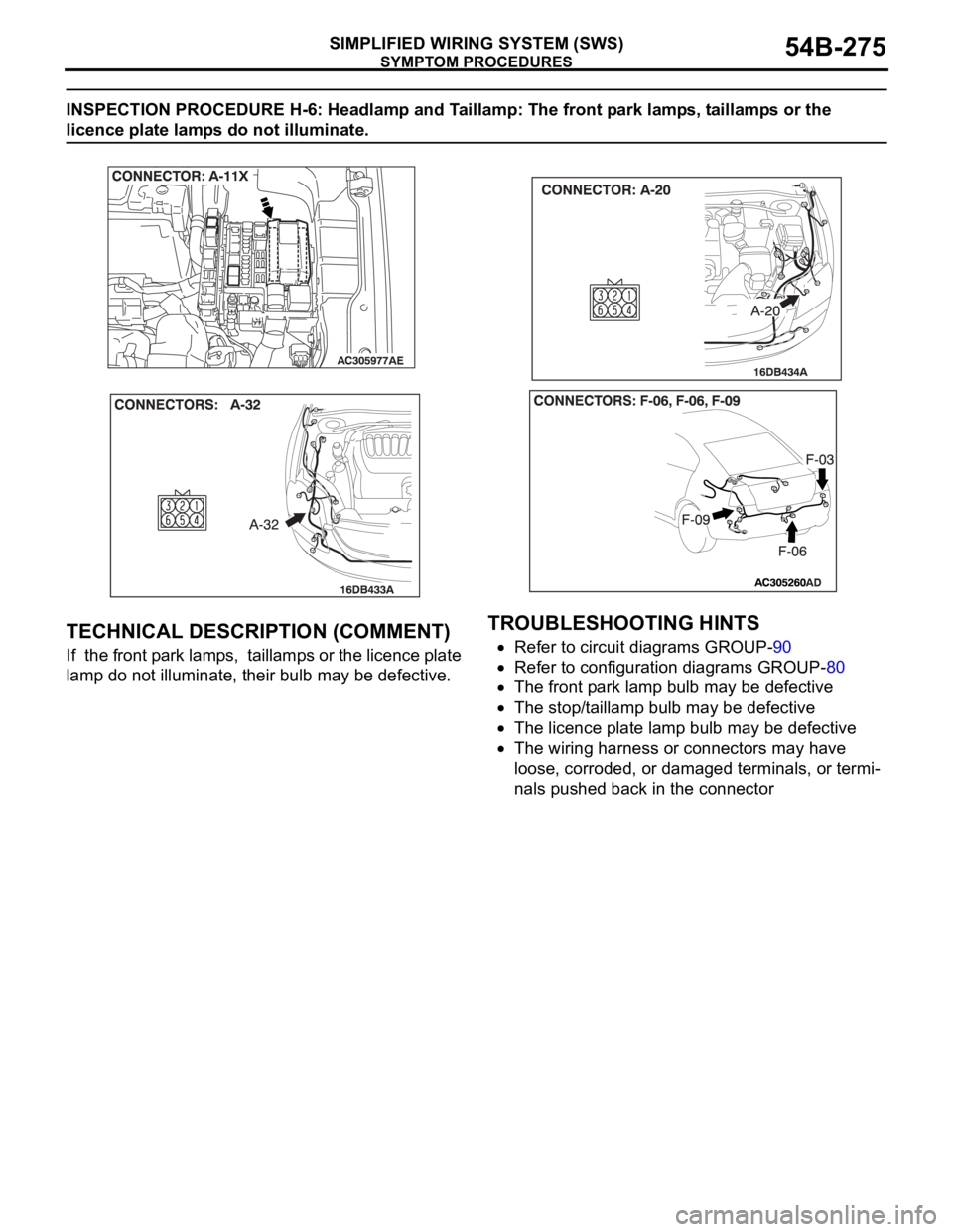
INSPECTION PROCEDURE H-6: Headlamp and Taillamp: The front park lamps, taillamps or the
licence plate lamps do not illuminate.
.
TECHNICAL DESCRIPTION (COMMENT)
If the front park lamps, taillamps or the licence plate
lamp do not illuminate, their bulb may be defective.
.
TROUBLESHOOTING HINTS
Refer to circuit diagrams GROUP-90
Refer to configuration diagrams GROUP-80
The front park lamp bulb may be defective
The stop/taillamp bulb may be defective
The licence plate lamp bulb may be defective
The wiring harness or connectors may have
loose, corroded, or damaged terminals, or termi-
nals pushed back in the connector
.
Page 290 of 1500
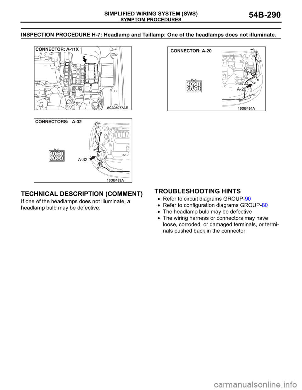
SYMPTOM PROCEDURES
SIMPLIFIED WIRING SYSTEM (SWS)54B-290
INSPECTION PROCEDURE H-7: Headlamp and Taillamp: One of the headlamps does not illuminate.
.
TECHNICAL DESCRIPTION (COMMENT)
If one of the headlamps does not illuminate, a
headlamp bulb may be defective.
.
TROUBLESHOOTING HINTS
Refer to circuit diagrams GROUP-90
Refer to configuration diagrams GROUP-80
The headlamp bulb may be defective
The wiring harness or connectors may have
loose, corroded, or damaged terminals, or termi-
nals pushed back in the connector
.
Page 301 of 1500
SYMPTOM PROCEDURES
SIMPLIFIED WIRING SYSTEM (SWS)54B-301
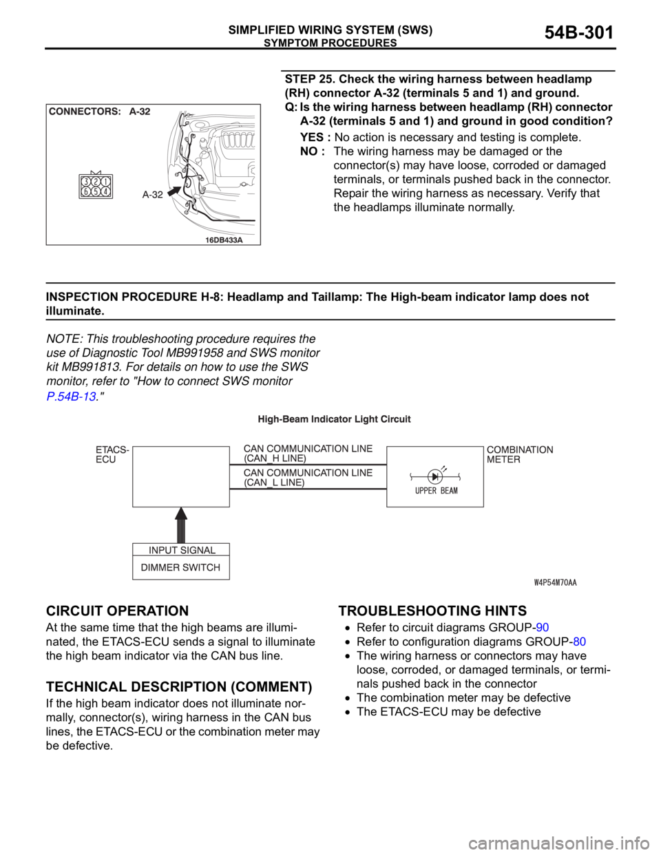
STEP 25. Check the wiring harness between headlamp
(RH) connector A-32 (terminals 5 and 1) and ground.
Q: Is the wiring harness between headlamp (RH) connector
A-32 (terminals 5 and 1) and ground in good condition?
YES : No action is necessary and testing is complete.
NO : The wiring harness may be damaged or the
connector(s) may have loose, corroded or damaged
terminals, or terminals pushed back in the connector.
Repair the wiring harness as necessary. Verify that
the headlamps illuminate normally.
INSPECTION PROCEDURE H-8: Headlamp and Taillamp: The High-beam indicator lamp does not
illuminate.
NOTE: This troubleshooting procedure requires the
use of Diagnostic Tool MB991958 and SWS monitor
kit MB991813. For details on how to use the SWS
monitor, refer to "How to connect SWS monitor
P.54B-13."
.
CIRCUIT OPERATION
At the same time that the high beams are illumi-
nated, the ETACS-ECU sends a signal to illuminate
the high beam indicator via the CAN bus line.
.
TECHNICAL DESCRIPTION (COMMENT)
If the high beam indicator does not illuminate nor-
mally, connector(s), wiring harness in the CAN bus
lines, the ETACS-ECU or the combination meter may
be defective.
.
TROUBLESHOOTING HINTS
Refer to circuit diagrams GROUP-90
Refer to configuration diagrams GROUP-80
The wiring harness or connectors may have
loose, corroded, or damaged terminals, or termi-
nals pushed back in the connector
The combination meter may be defective
The ETACS-ECU may be defective
.
Page 305 of 1500

SYMPTOM PROCEDURES
SIMPLIFIED WIRING SYSTEM (SWS)54B-305
INSPECTION PROCEDURE H-9: Headlamp and Taillamp: Headlamp automatic shutoff function does
not work normally.
NOTE: This troubleshooting procedure requires the
use of Diagnostic Tool MB991958 and SWS monitor
kit MB991813. For details on how to use the SWS
monitor, refer to "How to connect SWS monitor
P.54B-13."
.
CIRCUIT OPERATION
The ETACS-ECU operates the headlamp automatic
shutdown function according to the following signals:
Ignition switch (IG1): OFF
Driver's door switch: ON
Taillamp switch: ON
Headlamp switch: ON
The ETACS-ECU operates the headlamp automatic
shutdown function under the following conditions:
Ignition key: Other than "ON" position
Driver's door: open
Taillamps or headlamps: on
.
TECHNICAL DESCRIPTION (COMMENT)
If the function does not work normally, the input cir-
cuit system from the switches, the ETACS-ECU or
the front-ECU may be defective (refer to "CIRCUIT
OPERATION").
.
TROUBLESHOOTING HINTS
Refer to circuit diagrams GROUP-90
Refer to configuration diagrams GROUP-80
Trouble in input signal system
The wiring harness or connectors may have
loose, corroded, or damaged terminals, or termi-
nals pushed back in the connector
The front-ECU may be defective