window MITSUBISHI 380 2005 Workshop Manual
[x] Cancel search | Manufacturer: MITSUBISHI, Model Year: 2005, Model line: 380, Model: MITSUBISHI 380 2005Pages: 1500, PDF Size: 47.87 MB
Page 1106 of 1500
DOOR
BODY42-39
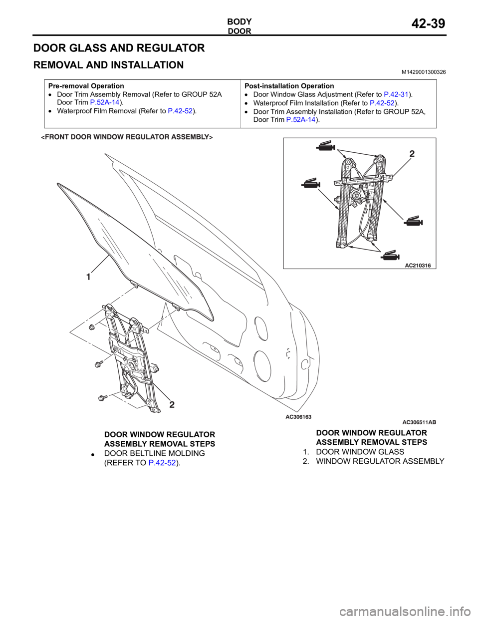
DOOR GLASS AND REGULATOR
REMOVAL AND INSTALLATIONM1429001300326
Pre-removal Operation
Door Trim Assembly Removal (Refer to GROUP 52A
Door Trim P.52A-14).
Waterproof Film Removal (Refer to P.42-52).Post-installation Operation
Door Window Glass Adjustment (Refer to P.42-31).
Waterproof Film Installation (Refer to P.42-52).
Door Trim Assembly Installation (Refer to GROUP 52A,
Door Trim P.52A-14).
DOOR WINDOW REGULATOR
ASSEMBLY REMOVAL STEPS
DOOR BELTLINE MOLDING
(REFER TO P.42-52).1. DOOR WINDOW GLASS
2. WINDOW REGULATOR ASSEMBLYDOOR WINDOW REGULATOR
ASSEMBLY REMOVAL STEPS
Page 1107 of 1500
DOOR
BODY42-40
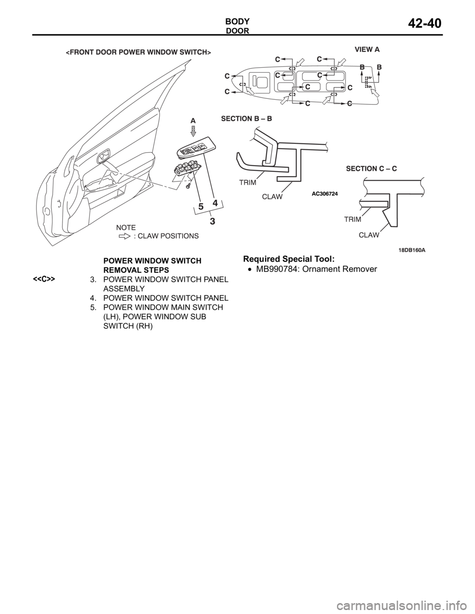
Required Special Tool:
MB990784: Ornament Remover
POWER WINDOW SWITCH
REMOVAL STEPS
<
ASSEMBLY
4. POWER WINDOW SWITCH PANEL
5. POWER WINDOW MAIN SWITCH
(LH), POWER WINDOW SUB
SWITCH (RH)
Page 1108 of 1500
DOOR
BODY42-41
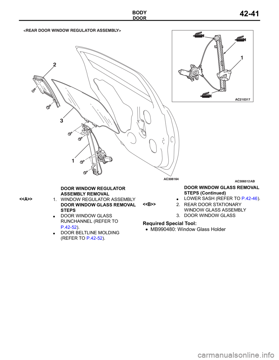
Required Special Tool:
MB990480: Window Glass Holder
DOOR WINDOW REGULATOR
ASSEMBLY REMOVAL
<>1. WINDOW REGULATOR ASSEMBLY
DOOR WINDOW GLASS REMOVAL
STEPS
DOOR WINDOW GLASS
RUNCHANNEL (REFER TO
P.42-52).
DOOR BELTLINE MOLDING
(REFER TO P.42-52).
LOWER SASH (REFER TO P.42-46).
<>2. REAR DOOR STATIONARY
WINDOW GLASS ASSEMBLY
3. DOOR WINDOW GLASSDOOR WINDOW GLASS REMOVAL
STEPS (Continued)
Page 1109 of 1500
DOOR
BODY42-42
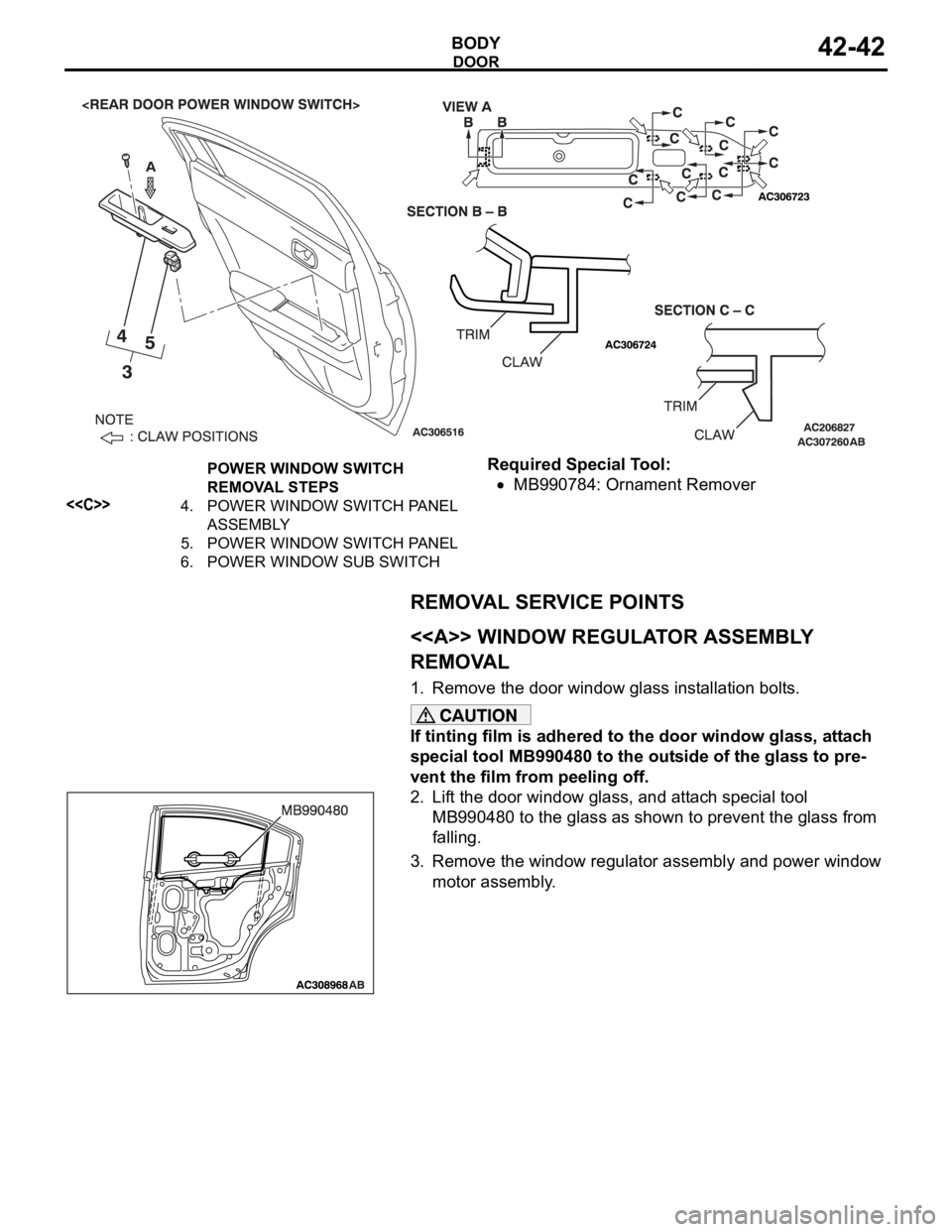
Required Special Tool:
MB990784: Ornament Remover
REMOVAL SERVICE POINTS
.
<> WINDOW REGULATOR ASSEMBLY
REMOVAL
1. Remove the door window glass installation bolts.
If tinting film is adhered to the door window glass, attach
special tool MB990480 to the outside of the glass to pre-
vent the film from peeling off.
2. Lift the door window glass, and attach special tool
MB990480 to the glass as shown to prevent the glass from
falling.
3. Remove the window regulator assembly and power window
motor assembly.
.
POWER WINDOW SWITCH
REMOVAL STEPS
<
ASSEMBLY
5. POWER WINDOW SWITCH PANEL
6. POWER WINDOW SUB SWITCH
Page 1110 of 1500
DOOR
BODY42-43
<> REAR DOOR STATIONARY WINDOW
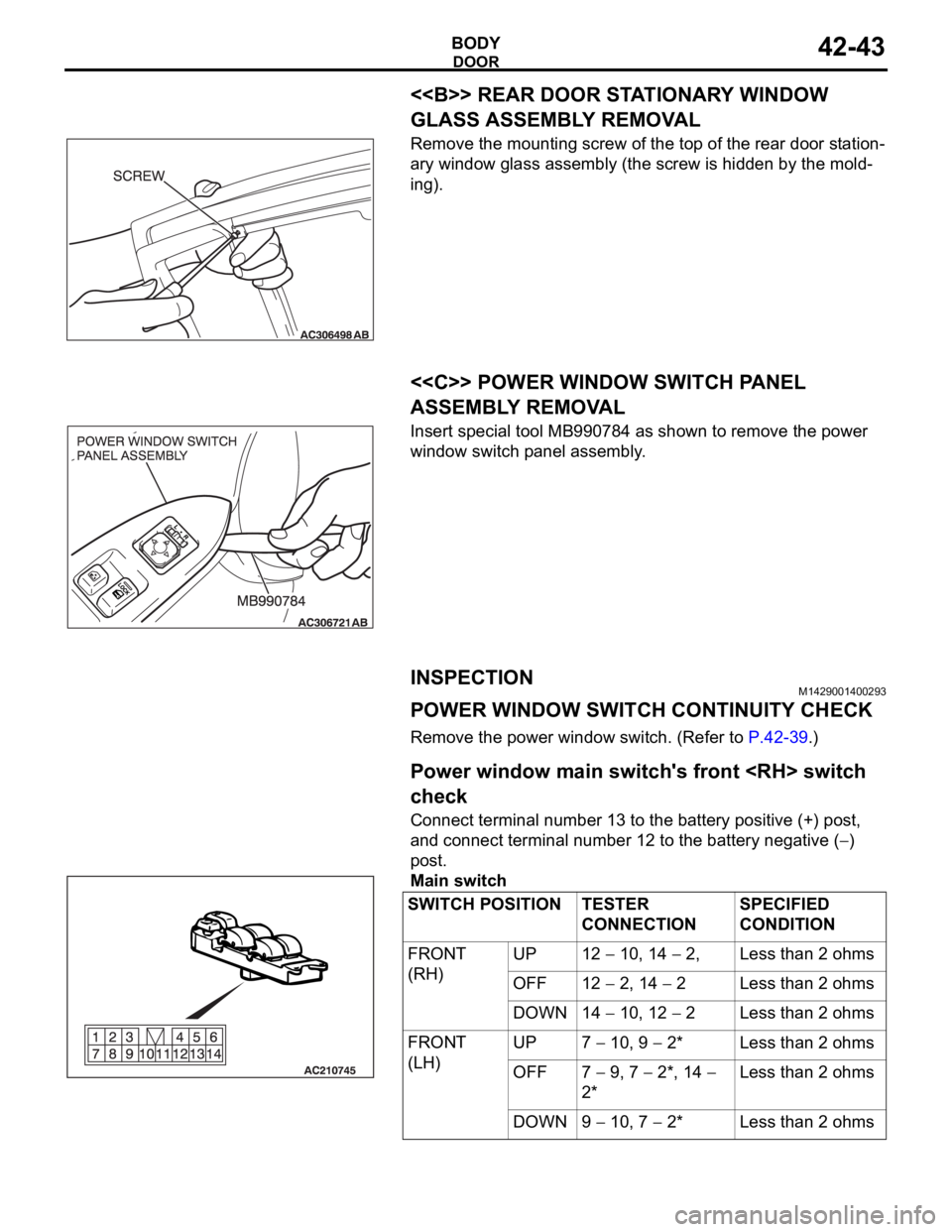
GLASS ASSEMBLY REMOVAL
Remove the mounting screw of the top of the rear door station-
ary window glass assembly (the screw is hidden by the mold-
ing).
.
<
ASSEMBLY REMOVAL
Insert special tool MB990784 as shown to remove the power
window switch panel assembly.
INSPECTIONM1429001400293
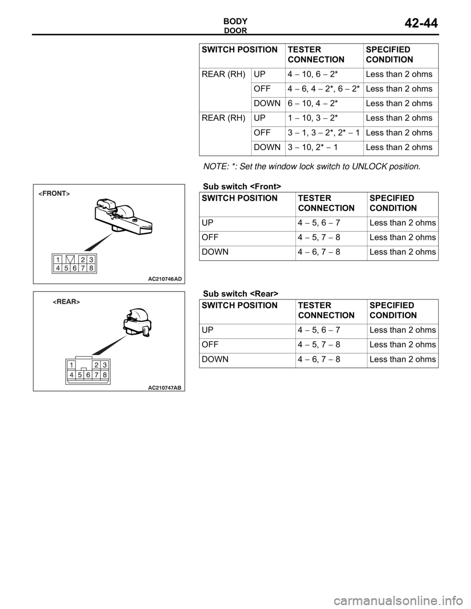
POWER WINDOW SWITCH CONTINUITY CHECK
Remove the power window switch. (Refer to P.42-39.).
Power window main switch's front
check
Connect terminal number 13 to the battery positive (+) post,
and connect terminal number 12 to the battery negative (
)
post.
Main switch
SWITCH POSITION TESTER
CONNECTIONSPECIFIED
CONDITION
FRONT
(RH)UP 12
10, 14 2, Less than 2 ohms
OFF 12
2, 14 2 Less than 2 ohms
DOWN 14
10, 12 2 Less than 2 ohms
FRONT
(LH)UP 7
10, 9 2* Less than 2 ohms
OFF 7
9, 7 2*, 14
2*Less than 2 ohms
DOWN 9
10, 7 2* Less than 2 ohms
Page 1111 of 1500
DOOR
BODY42-44
NOTE: *: Set the window lock switch to UNLOCK position.
.Sub switch
Sub switch
10, 6 2* Less than 2 ohms
OFF 4
6, 4 2*, 6 2* Less than 2 ohms
DOWN 6
10, 4 2* Less than 2 ohms
REAR (RH) UP 1
10, 3 2* Less than 2 ohms
OFF 3
1, 3 2*, 2* 1 Less than 2 ohms
DOWN 3
10, 2* 1 Less than 2 ohms
SWITCH POSITION TESTER
CONNECTIONSPECIFIED
CONDITION
UP 4
5, 6 7 Less than 2 ohms
OFF 4
5, 7 8 Less than 2 ohms
DOWN 4
6, 7 8 Less than 2 ohms
SWITCH POSITION TESTER
CONNECTIONSPECIFIED
CONDITION
UP 4
5, 6 7 Less than 2 ohms
OFF 4
5, 7 8 Less than 2 ohms
DOWN 4
6, 7 8 Less than 2 ohms SWITCH POSITION TESTER
CONNECTIONSPECIFIED
CONDITION
Page 1112 of 1500
DOOR
BODY42-45
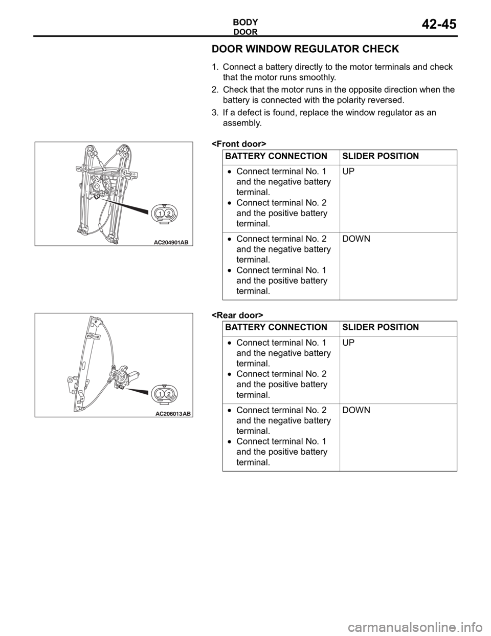
DOOR WINDOW REGULATOR CHECK
.
1. Connect a battery directly to the motor terminals and check
that the motor runs smoothly.
2. Check that the motor runs in the opposite direction when the
battery is connected with the polarity reversed.
3. If a defect is found, replace the window regulator as an
assembly.
.
.
Connect terminal No. 1
and the negative battery
terminal.
Connect terminal No. 2
and the positive battery
terminal.UP
Connect terminal No. 2
and the negative battery
terminal.
Connect terminal No. 1
and the positive battery
terminal.DOWN
BATTERY CONNECTION SLIDER POSITION
Connect terminal No. 1
and the negative battery
terminal.
Connect terminal No. 2
and the positive battery
terminal.UP
Connect terminal No. 2
and the negative battery
terminal.
Connect terminal No. 1
and the positive battery
terminal.DOWN
Page 1115 of 1500
Page 1118 of 1500
DOOR
BODY42-51
FUEL LID D00R ACTUATOR CHECK
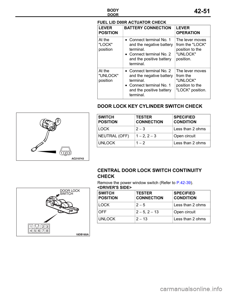
DOOR LOCK KEY CYLINDER SWITCH CHECK
CENTRAL DOOR LOCK SWITCH CONTINUITY
CHECK
Remove the power window switch (Refer to P.42-39).
POSITIONBATTERY CONNECTION LEVER
OPERATION
At the
"LOCK"
position
Connect terminal No. 1
and the negative battery
terminal.
Connect terminal No. 2
and the positive battery
terminal.The lever moves
from the "LOCK"
position to the
"UNLOCK"
position.
At the
"UNLOCK"
position
Connect terminal No. 2
and the negative battery
terminal.
Connect terminal No. 1
and the positive battery
terminal.The lever moves
from the
"UNLOCK"
position to the
"LOCK" position.
SWITCH
POSITIONTESTER
CONNECTIONSPECIFIED
CONDITION
LOCK 2
3 Less than 2 ohms
NEUTRAL (OFF) 1
2, 2 3 Open circuit
UNLOCK 1
2 Less than 2 ohms
SWITCH
POSITIONTESTER
CONNECTIONSPECIFIED
CONDITION
LOCK 2
5 Less than 2 ohms
OFF 2
5, 2 13 Open circuit
UNLOCK 2
13 Less than 2 ohms
Page 1119 of 1500
DOOR
BODY42-52
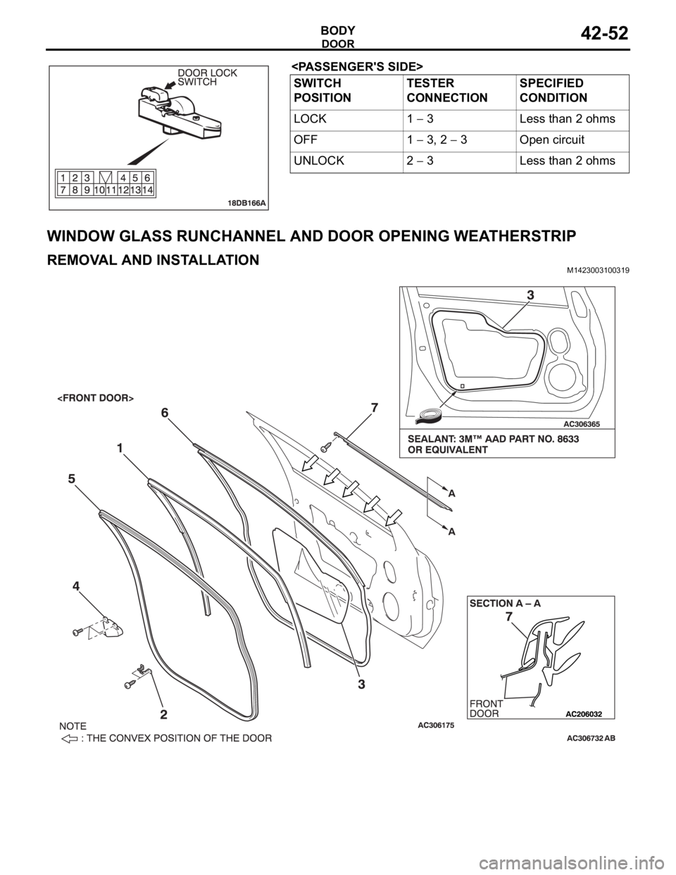
WINDOW GLASS RUNCHANNEL AND DOOR OPENING WEATHERSTRIP
REMOVAL AND INSTALLATIONM1423003100319
SWITCH
POSITIONTESTER
CONNECTIONSPECIFIED
CONDITION
LOCK 1
3 Less than 2 ohms
OFF 1
3, 2 3 Open circuit
UNLOCK 2
3 Less than 2 ohms