window MITSUBISHI 380 2005 Manual PDF
[x] Cancel search | Manufacturer: MITSUBISHI, Model Year: 2005, Model line: 380, Model: MITSUBISHI 380 2005Pages: 1500, PDF Size: 47.87 MB
Page 639 of 1500
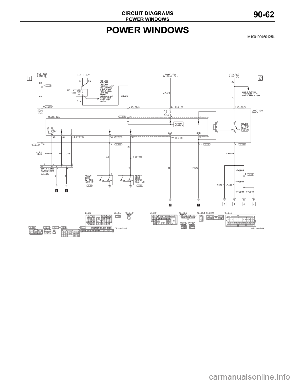
POWER WINDOWS
CIRCUIT DIAGRAMS90-62
POWER WINDOWSM1901004601254
Page 640 of 1500
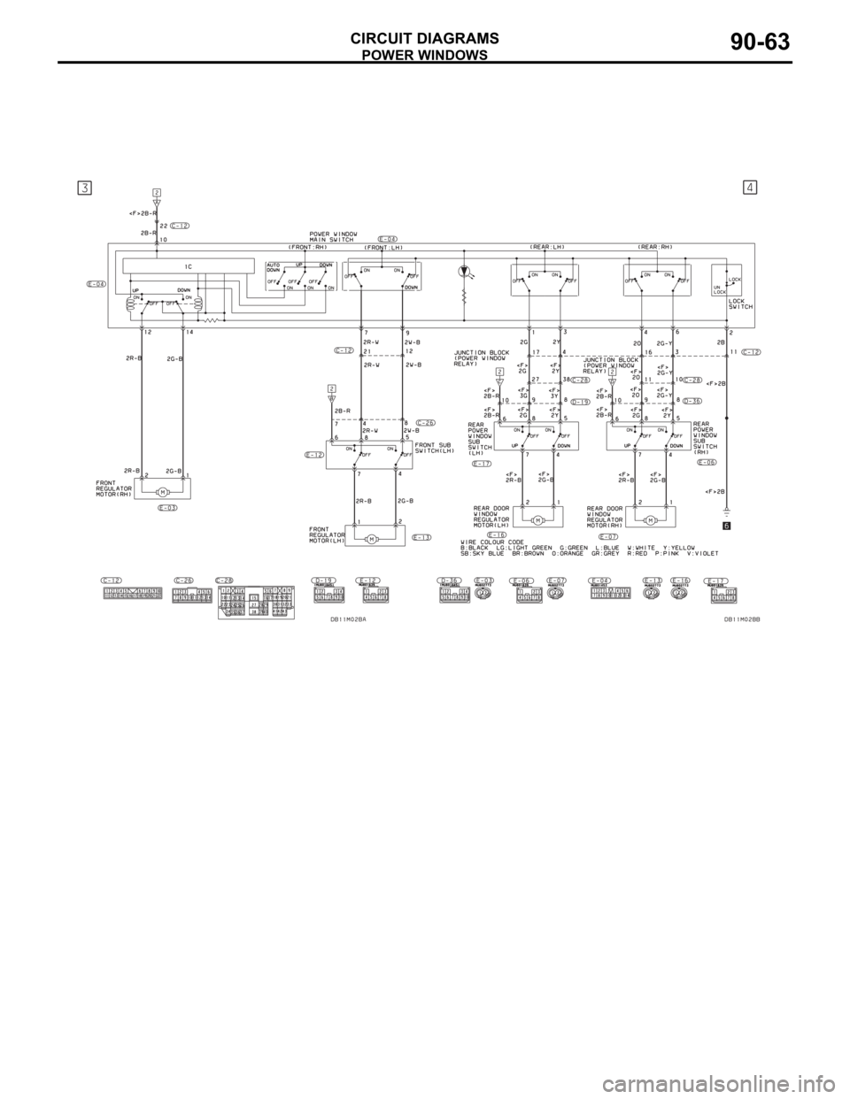
POWER WINDOWS
CIRCUIT DIAGRAMS90-63
Page 822 of 1500
AUTO A/C DIAGNOSIS
HEATER, AIR CONDITIONING AND VENTILATION55-121
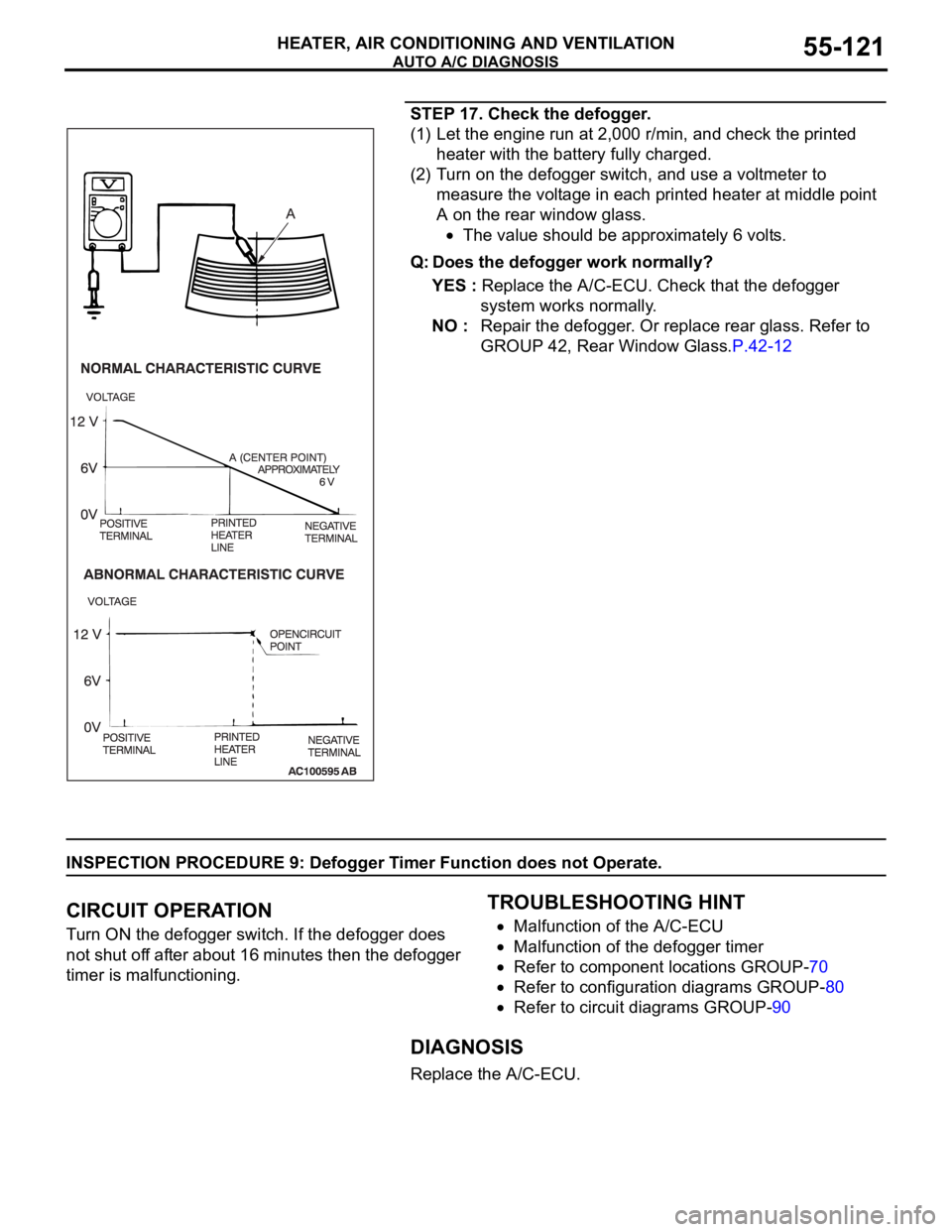
STEP 17. Check the defogger.
(1) Let the engine run at 2,000 r/min, and check the printed
heater with the battery fully charged.
(2) Turn on the defogger switch, and use a voltmeter to
measure the voltage in each printed heater at middle point
A on the rear window glass.
The value should be approximately 6 volts.
Q: Does the defogger work normally?
YES : Replace the A/C-ECU. Check that the defogger
system works normally.
NO : Repair the defogger. Or replace rear glass. Refer to
GROUP 42, Rear Window Glass.P.42-12
INSPECTION PROCEDURE 9: Defogger Timer Function does not Operate.
.
CIRCUIT OPERATION
Turn ON the defogger switch. If the defogger does
not shut off after about 16 minutes then the defogger
timer is malfunctioning.
.
TROUBLESHOOTING HINT
Malfunction of the A/C-ECU
Malfunction of the defogger timer
Refer to component locations GROUP-70
Refer to configuration diagrams GROUP-80
Refer to circuit diagrams GROUP-90
DIAGNOSIS
Replace the A/C-ECU.
Page 835 of 1500

AUTO A/C DIAGNOSIS
HEATER, AIR CONDITIONING AND VENTILATION55-134
Air outlet c/o
potentiometer55 Mode selection
damper control
motor potentiometerIgnition switch: ON Damper
positionOpening degree (V)
FA C E A p pr o x . 5
FOOT Approx. 3.75
FOOT/DEF. Approx. 2.5
DEF. Approx. 1.75
Air outlet c/o
potentiometer
(target)56 Target value for
mode selection
damper control
motor potentiometerIgnition switch: ON Damper
positionOpening degree (V)
FA C E A p pr o x . 5
FOOT Approx. 3.75
FOOT/DEF. Approx. 2.5
DEF. Approx. 1.75
In/out air
changeover
damper motor65 Outside/inside air
selection damper
control motorIgnition switch: ON Damper set
positionDamper position
Fresh air
positionFRESH
Air recirculation
positionRECIRC
Front blower fan 68 Blower motor Ignition switch: ON The actual air
volume (blower
motor speed)
corresponds to the
air volume shown on
the diagnostic tool.
Front blower
motor voltage 71 Blower motor Ignition switch: ON The air volume set
by the heater control
corresponds to the
value shown on the
diagnostic tool. (V)
Air conditioning
switch state1 Air conditioning
switchIgnition switch: ON Air conditioning
switch: ONDiagnostic tool
indication: "pressed"
Air conditioning
switch: OFFDiagnostic tool
indication: "release"
Rear defogger
switch state7 Rear window
defogger switchIgnition switch: ON Rear window
defogger
switch: ONDiagnostic tool
indication: "pressed"
Rear window
defogger
switch: OFFDiagnostic tool
indication: "release"
Refrigerant
pressure73 Refrigerant pressure Ignition switch: ON The diagnostic tool
indication is normal MUT-III
DIAGNOSTIC
TOOL DISPLAYITEM
NO.INSPECTION ITEM INSPECTION REQUIREMENT NORMAL VALUE
Page 837 of 1500

AUTO A/C DIAGNOSIS
HEATER, AIR CONDITIONING AND VENTILATION55-136
ACTUATOR TEST REFERENCEM1554005200133
MUT-III DIAGNOSTIC
TOOL DISPLAYITEM NO. INSPECTION ITEM DRIVE CONTENT
Blower fan: OFF 83 Blower motor OFF
Blower fan: Middle 84 Middle speed
Blower fan: High 85 High speed
Air mix damper motor:
0%42 Air mixing damper control motor Opening degree: approx.
0% (Max cool)
Air mix damper motor:
100%43 Opening degree: approx.
100% (Max hot)
Air outlet c/o damper:
FA C E70 Mode selection damper control
motorFA C E
Air outlet c/o damper: Bi_
Level67 FOOT/FACE
Air outlet c/o damper:
FOOT71 FOOT
Air outlet c/o damper:
DEF/FOOT69 DEF/FOOT
Air outlet c/o damper:
DEF68 DEF
Idle up request: high load 74 Idle speed HIGH idle up
Idle up request: low load 75 LOW idle up
Idle up request: OFF 76 OFF
Rear defogger switch:
OFF40 Rear window defogger switch Rear window defogger: OFF
Rear defogger switch:
ON41 Rear window defogger: ON
Idle up request: OFF 50 Idle up operation Idle up: OFF
Idle up request: low load 51 Idle up: low load
Idle up request: high load 52 Idle up: high load
Condenser: 0% 77 Condenser fan OFF
Condenser: 50% 79 Middle speed
Rheostat: 0% 80 Rheostat- Illumination control OFF
Rheostat: 100% 81 Full duty
Rheostat: 50% 82 Half duty
Page 844 of 1500
ON-VEHICLE SERVICE
HEATER, AIR CONDITIONING AND VENTILATION55-143
PERFORMANCE TEST M1552001400526
The vehicles to be tested should be parked out of direct sun-
light.
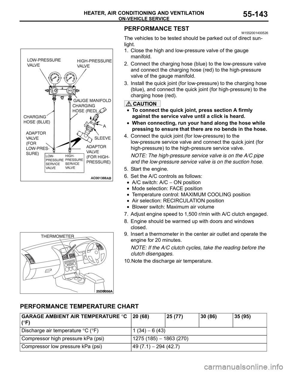
1. Close the high and low-pressure valve of the gauge
manifold.
2. Connect the charging hose (blue) to the low-pressure valve
and connect the charging hose (red) to the high-pressure
valve of the gauge manifold.
3. Install the quick joint (for low-pressure) to the charging hose
(blue), and connect the quick joint (for high-pressure) to the
charging hose (red).
To connect the quick joint, press section A firmly
against the service valve until a click is heard.
When connecting, run your hand along the hose while
pressing to ensure that there are no bends in the hose.
4. Connect the quick joint (for low-pressure) to the
low-pressure service valve and connect the quick joint (for
high-pressure) to the high-pressure service valve.
NOTE: The high-pressure service valve is on the A/C pipe
and the low-pressure service valve is on the suction hose.
5. Start the engine.
6. Set the A/C controls as follows:
A/C switch: A/C ON position
Mode selection: FACE position
Temperature control: MAXIMUM COOLING position
Air selection: RECIRCULATION position
Blower switch: Maximum air volume
7. Adjust engine speed to 1,500 r/min with A/C clutch engaged.
8. Engine should be warmed up with doors and windows
closed.
9. Insert a thermometer in the center air outlet and operate the
engine for 20 minutes.
NOTE: If the A/C clutch cycles, take the reading before the
clutch disengages.
10.Note the discharge air temperature.
PERFORMANCE TEMPERATURE CHART
GARAGE AMBIENT AIR TEMPERATURE C
(
F)20 (68) 25 (77) 30 (86) 35 (95)
Discharge air temperature
C (F) 1 (34) 6 (43)
Compressor high pressure kPa (psi) 1275 (185)
1863 (270)
Compressor low pressure kPa (psi) 49 (7.1)
294 (42.7)
Page 885 of 1500
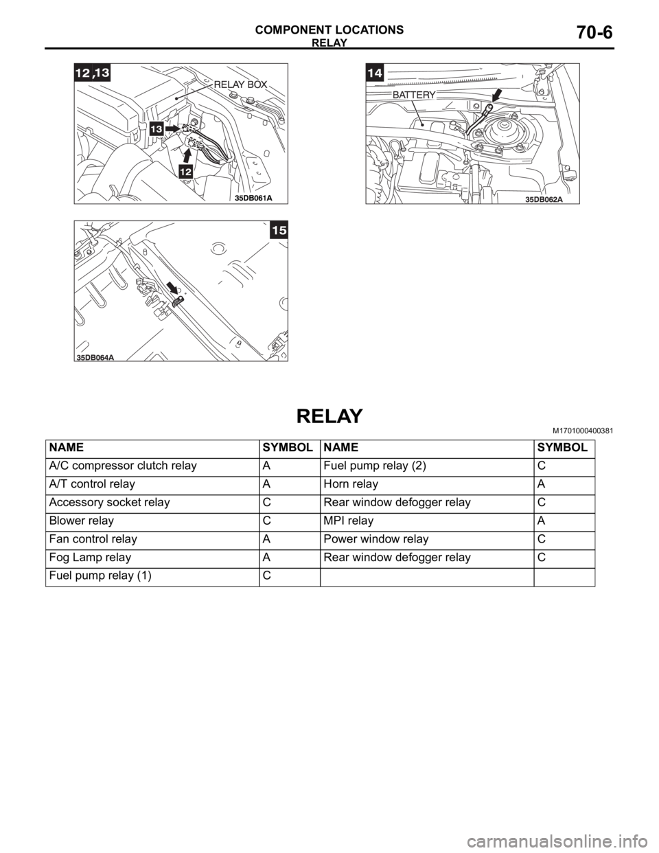
RELAY
COMPONENT LOCATIONS70-6
RELAYM1701000400381
NAME SYMBOL NAME SYMBOL
A/C compressor clutch relay A Fuel pump relay (2) C
A/T control relay A Horn relay A
Accessory socket relay C Rear window defogger relay C
Blower relay C MPI relay A
Fan control relay A Power window relay C
Fog Lamp relay A Rear window defogger relay C
Fuel pump relay (1) C
Page 893 of 1500
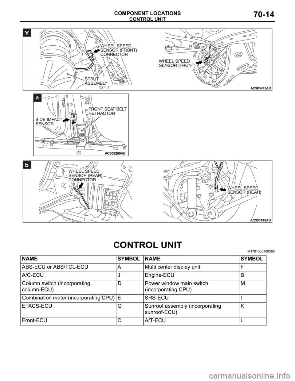
CONTROL UNIT
COMPONENT LOCATIONS70-14
CONTROL UNITM1701000700360
NAME SYMBOL NAME SYMBOL
ABS-ECU or ABS/TCL-ECU A Multi center display unit F
A/C-ECU J Engine-ECU B
Column switch (incorporating
column-ECU)D Power window main switch
(incorporating CPU)M
Combination meter (incorporating CPU) E SRS-ECU I
ETACS-ECU G Sunroof assembly (incorporating
sunroof-ECU)K
Front-ECU C A/T-ECU L
Page 1062 of 1500
DOOR MIRROR
EXTERIOR51-29
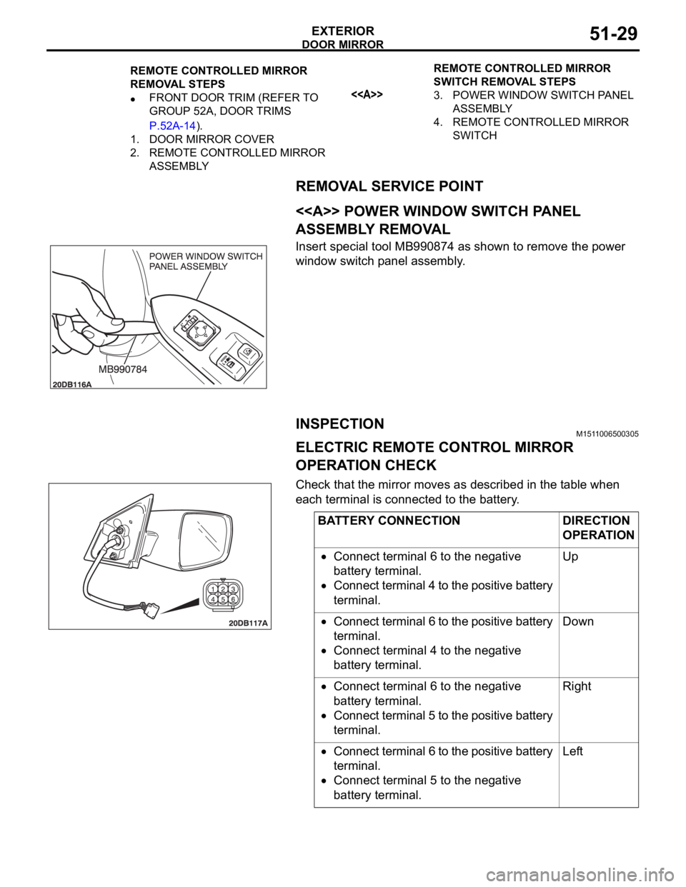
REMOVAL SERVICE POINT
.
<> POWER WINDOW SWITCH PANEL
ASSEMBLY REMOVAL
Insert special tool MB990874 as shown to remove the power
window switch panel assembly.
INSPECTIONM1511006500305
ELECTRIC REMOTE CONTROL MIRROR
OPERATION CHECK
Check that the mirror moves as described in the table when
each terminal is connected to the battery.
REMOTE CONTROLLED MIRROR
REMOVAL STEPS
FRONT DOOR TRIM (REFER TO
GROUP 52A, DOOR TRIMS
P.52A-14).
1. DOOR MIRROR COVER
2. REMOTE CONTROLLED MIRROR
ASSEMBLYREMOTE CONTROLLED MIRROR
SWITCH REMOVAL STEPS<>3. POWER WINDOW SWITCH PANEL
ASSEMBLY
4. REMOTE CONTROLLED MIRROR
SWITCH
BATTERY CONNECTION DIRECTION
OPERATION
Connect terminal 6 to the negative
battery terminal.
Connect terminal 4 to the positive battery
terminal.Up
Connect terminal 6 to the positive battery
terminal.
Connect terminal 4 to the negative
battery terminal.Down
Connect terminal 6 to the negative
battery terminal.
Connect terminal 5 to the positive battery
terminal.Right
Connect terminal 6 to the positive battery
terminal.
Connect terminal 5 to the negative
battery terminal.Left
Page 1068 of 1500
42-1
GROUP 42
BODY
CONTENTS
HOOD . . . . . . . . . . . . . . . . . . . . .
42-4
BODY DIAGNOSIS . . . . . . . . . . . .
42-4
INTRODUCTION TO HOOD DIAGNOSIS42-4
HOOD DIAGNOSTIC TROUBLESHOOTING
STRATEGY . . . . . . . . . . . . . . . . . . . . . . 42-4
SYMPTOM CHART . . . . . . . . . . . . . . . . 42-4
SYMPTOM PROCEDURES . . . . . . . . . 42-4
ON-VEHICLE SERVICE. . . . . . . . .42-6
ADJUSTMENT OF CLEARANCE
AROUND HOOD . . . . . . . . . . . . . . . . . . 42-6
ALIGNMENT OF HOOD LATCH AND
STRIKER . . . . . . . . . . . . . . . . . . . . . . . . 42-6
ADJUSTMENT OF HOOD HEIGHT . . . 42-7
HOOD . . . . . . . . . . . . . . . . . . . . . . .42-8
REMOVAL AND INSTALLATION . . . . . 42-8
FENDER . . . . . . . . . . . . . . . . . . .42-10
REMOVAL AND INSTALLATION .
42-10
FUEL FILLER LID . . . . . . . . . . .42-11
REMOVAL AND INSTALLATION .
42-11
STRUT TOWER BAR . . . . . . . . 42-12
REMOVAL AND INSTALLATION .
42-12
WINDOW GLASS . . . . . . . . . . . 42-12
GENERAL . . . . . . . . . . . . . . . . . . . .
42-12
WINDOW GLASS DIAGNOSIS . . .42-14
INTRODUCTION TO WINDOW GLASS
DIAGNOSIS . . . . . . . . . . . . . . . . . . . . . . 42-14
WINDOW GLASS DIAGNOSTIC
TROUBLESHOOTING STRATEGY . . . . 42-14
WINDOW GLASS DIAGNOSTIC TROUBLE
SYMPTOM CHART . . . . . . . . . . . . . . . . 42-14
SYMPTOM PROCEDURES . . . . . . . . . . 42-14
SPECIAL TOOL . . . . . . . . . . . . . . .42-14
WINDSHIELD . . . . . . . . . . . . . . . . .42-15
REMOVAL AND INSTALLATION . . . . . . 42-15
REAR WINDOW GLASS . . . . . . . .42-20
REMOVAL AND INSTALLATION . . . . . . 42-20
Continued on next page