window MITSUBISHI 380 2005 Manual Online
[x] Cancel search | Manufacturer: MITSUBISHI, Model Year: 2005, Model line: 380, Model: MITSUBISHI 380 2005Pages: 1500, PDF Size: 47.87 MB
Page 1069 of 1500
BODY42-2
DOOR . . . . . . . . . . . . . . . . . . . . . . . . .42-23
GENERAL DESCRIPTION . . . . . .
42-23
CENTRAL DOOR LOCKING SYSTEM
DIAGNOSIS . . . . . . . . . . . . . . . . . . . . . . 42-23
POWER WINDOW DIAGNOSIS . . . . . . 42-23
DOOR DIAGNOSIS . . . . . . . . . . . . . . . . 42-23
INTRODUCTION TO GLASS AND DOOR
DIAGNOSIS . . . . . . . . . . . . . . . . . . . . . . 42-23
GLASS AND DOOR DIAGNOSTIC
TROUBLESHOOTING STRATEGY . . . 42-23
SYMPTOM CHART . . . . . . . . . . . . . . . . 42-24
SYMPTOM PROCEDURES . . . . . . . . . 42-24
HOW TO LOCATE WIND NOISE . . . . . 42-27
SPECIAL TOOLS. . . . . . . . . . . . . .42-28
ON-VEHICLE SERVICE. . . . . . . . .42-30
DOOR FIT ADJUSTMENT. . . . . . . . . . . 42-30
DOOR WINDOW GLASS ADJUSTMENT42-31
GLASS SLIDING MECHANISM CHECK
AND ADJUSTMENT . . . . . . . . . . . . . . . 42-32
POWER WINDOW TIMER FUNCTION
CHECK . . . . . . . . . . . . . . . . . . . . . . . . . 42-32
POWER WINDOW OPERATING
CURRENT CHECK . . . . . . . . . . . . . . . . 42-33
POWER WINDOW RELAY CHECK . . . 42-33
CIRCUIT BREAKER (INCORPORATED IN
THE POWER WINDOW MOTOR)
INSPECTION . . . . . . . . . . . . . . . . . . . . . 42-34
POWER WINDOW CHECK . . . . . . . . . . 42-34
CENTRAL DOOR LOCKING SYSTEM
INSPECTION . . . . . . . . . . . . . . . . . . . . . 42-34
DOOR OUTSIDE HANDLE PLAY CHECK42-35
DOOR INSIDE HANDLE PLAY CHECK 42-35
DOOR ASSEMBLY . . . . . . . . . . . .42-37
REMOVAL AND INSTALLATION . . . . . 42-37
INSPECTION . . . . . . . . . . . . . . . . . . . . . 42-38
DOOR GLASS AND REGULATOR42-39
REMOVAL AND INSTALLATION . . . . . 42-39
INSPECTION . . . . . . . . . . . . . . . . . . . . . 42-43
DOOR HANDLE AND LATCH . . . .42-46
REMOVAL AND INSTALLATION . . . . . 42-46
INSPECTION . . . . . . . . . . . . . . . . . . . . . 42-49
WINDOW GLASS RUNCHANNEL
AND DOOR OPENING
WEATHERSTRIP . . . . . . . . . . . . . .
42-52
REMOVAL AND INSTALLATION . . . . . . 42-52
TRUNK LID. . . . . . . . . . . . . . . . 42-60
TRUNK LID DIAGNOSIS . . . . . . . .
42-60
INTRODUCTION TO TRUNK LID
DIAGNOSIS . . . . . . . . . . . . . . . . . . . . . . 42-60
TRUNK LID DIAGNOSTIC
TROUBLESHOOTING STRATEGY . . . . 42-60
SYMPTOM CHART . . . . . . . . . . . . . . . . 42-60
SYMPTOM PROCEDURES . . . . . . . . . . 42-60
ON-VEHICLE SERVICE . . . . . . . . .42-61
ADJUSTMENT OF CLEARANCE
AROUND TRUNK LID . . . . . . . . . . . . . . 42-61
TRUNK LID LATCH ADJUSTMENT. . . . 42-61
TRUNK LID HEIGHT ADJUSTMENT . . . 42-62
TRUNK LID . . . . . . . . . . . . . . . . . . .42-63
REMOVAL AND INSTALLATION . . . . . . 42-63
INSPECTION . . . . . . . . . . . . . . . . . . . . . 42-65
KEYLESS ENTRY SYSTEM 42-67
GENERAL DESCRIPTION . . . . . . .
42-67
KEYLESS ENTRY SYSTEM
DIAGNOSIS . . . . . . . . . . . . . . . . . .
42-68
SPECIAL TOOL . . . . . . . . . . . . . . .42-68
ON-VEHICLE SERVICE . . . . . . . . .42-69
TRANSMITTER BATTERY CHECK . . . . 42-69
HOW TO REPLACE THE TRANSMITTER
BATTERY . . . . . . . . . . . . . . . . . . . . . . . . 42-70
KEYLESS ENTRY SYSTEM INSPECTION42-71
KEYLESS ENTRY SYSTEM TIMER LOCK
FUNCTION INSPECTION . . . . . . . . . . . 42-71
ENABLING/DISABLING THE
ANSWERBACK FUNCTION . . . . . . . . . 42-72
HOW TO REGISTER SECRET CODE . 42-73
Continued on next page
Page 1079 of 1500
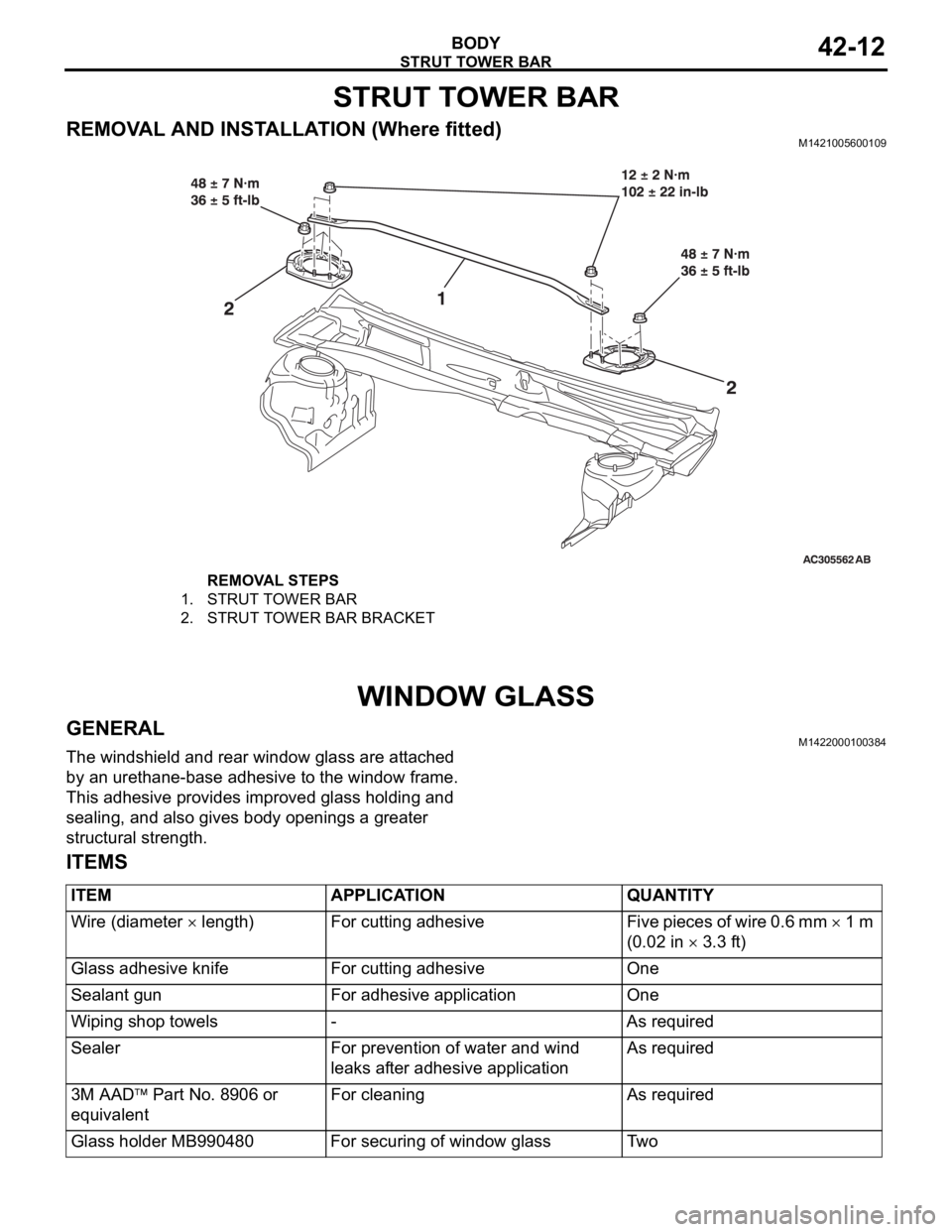
STRUT TOWER BAR
BODY42-12
STRUT TOWER BAR
REMOVAL AND INSTALLATION (Where fitted)M1421005600109
WINDOW GLASS
GENERALM1422000100384
The windshield and rear window glass are attached
by an urethane-base adhesive to the window frame.
This adhesive provides improved glass holding and
sealing, and also gives body openings a greater
structural strength.
ITEMS
REMOVAL STEPS
1. STRUT TOWER BAR
2. STRUT TOWER BAR BRACKET
ITEM APPLICATION QUANTITY
Wire (diameter
length) For cutting adhesive Five pieces of wire 0.6 mm 1 m
(0.02 in
3.3 ft)
Glass adhesive knife For cutting adhesive One
Sealant gun For adhesive application One
Wiping shop towels - As required
Sealer For prevention of water and wind
leaks after adhesive applicationAs required
3M AAD
Part No. 8906 or
equivalentFor cleaning As required
Glass holder MB990480 For securing of window glass Two
Page 1080 of 1500
WINDOW GLASS
BODY42-13
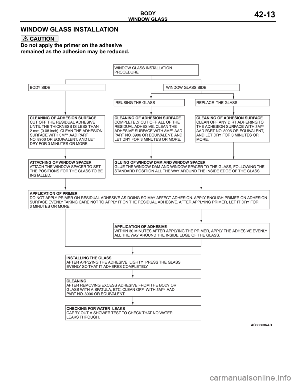
WINDOW GLASS INSTALLATION
Do not apply the primer on the adhesive
remained as the adhesion may be reduced.
Page 1081 of 1500
WINDOW GLASS
BODY42-14
WINDOW GLASS DIAGNOSIS
INTRODUCTION TO WINDOW GLASS DIAGNOSISM1422006700254
If water emerges from the following points, there is a
problem in the seal or body flange.Windshield
Rear window glass
WINDOW GLASS DIAGNOSTIC TROUBLESHOOTING STRATEGYM1422006800240
Use these steps to plan your diagnostic strategy. If
you follow them carefully, you will be sure that you
have exhausted most of the possible ways to find a
window glass fault.
1. Gather information from the customer.2. Verify that the condition described by the
customer exists.
3. Find the malfunction by following the Symptom
Chart.
4. Verify malfunction is eliminated.
WINDOW GLASS DIAGNOSTIC TROUBLE SYMPTOM CHARTM1422006900281
SYMPTOM PROCEDURES
INSPECTION PROCEDURE 1: Water Leak Through Windshield/Rear Window Glass
DIAGNOSIS
STEP 1. Check if the seal is faulty.
Q: Is the seal faulty?
YES :
Repair the seal, then go to Step 3.
NO : Go to Step 2.
STEP 2. Check if the body flange is deformed.
Q: Is the body flange deformed?
YES :
Replay the body flange, then go to Step 3.
NO : Go to Step 3.
STEP 3. Retest the system.
Q: Is any water leaking?
YES :
Return to Step 1.
NO : This diagnosis complete.
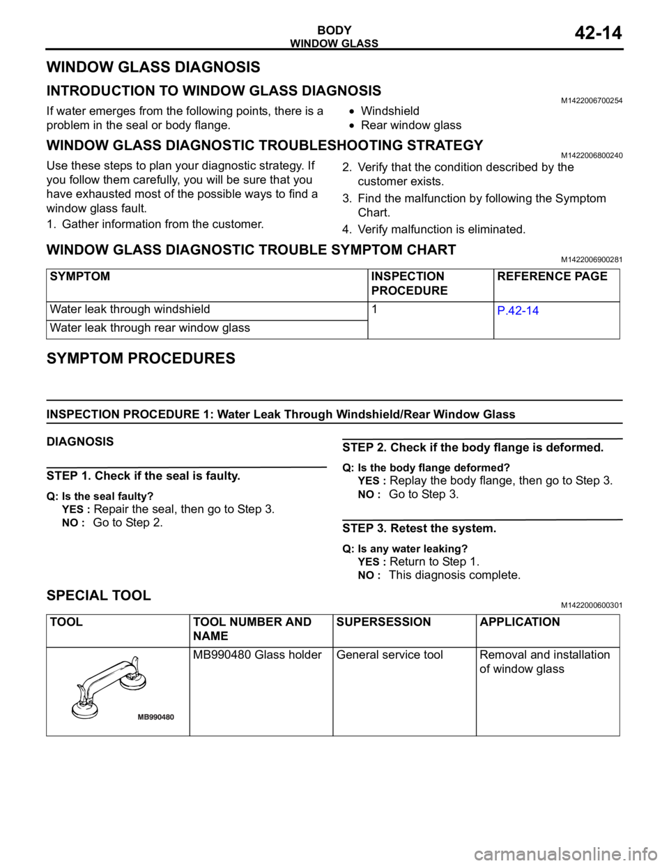
SPECIAL TOOLM1422000600301
SYMPTOM INSPECTION
PROCEDUREREFERENCE PAGE
Water leak through windshield 1
P.42-14
Water leak through rear window glass
TOOL TOOL NUMBER AND
NAMESUPERSESSION APPLICATION
MB990480 Glass holder General service tool Removal and installation
of window glass
Page 1082 of 1500
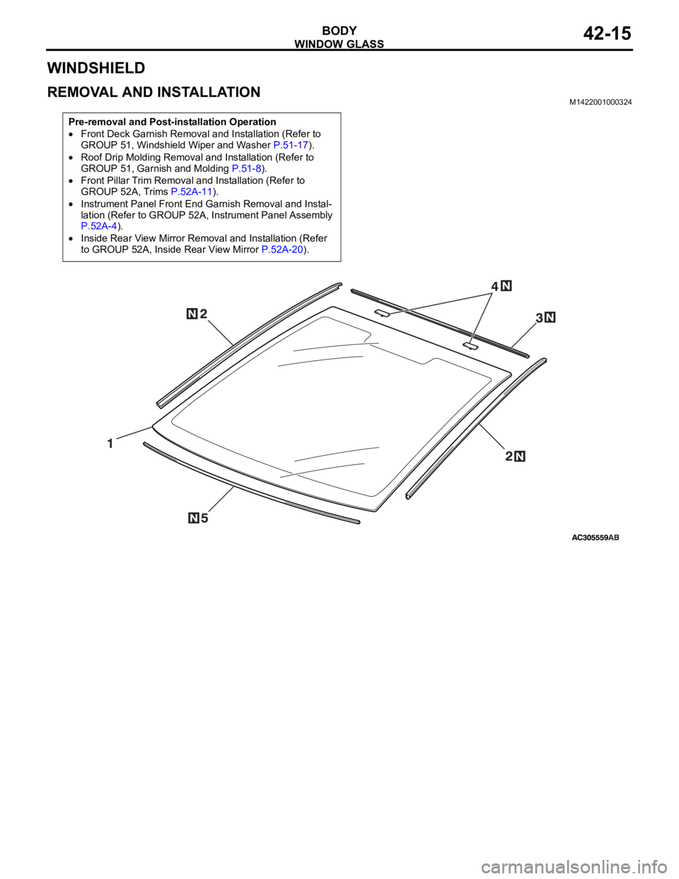
WINDOW GLASS
BODY42-15
WINDSHIELD
REMOVAL AND INSTALLATIONM1422001000324
Pre-removal and Post-installation Operation
Front Deck Garnish Removal and Installation (Refer to
GROUP 51, Windshield Wiper and Washer P.51-17).
Roof Drip Molding Removal and Installation (Refer to
GROUP 51, Garnish and Molding P.51-8).
Front Pillar Trim Removal and Installation (Refer to
GROUP 52A, Trims P.52A-11).
Instrument Panel Front End Garnish Removal and Instal-
lation (Refer to GROUP 52A, Instrument Panel Assembly
P.52A-4).
Inside Rear View Mirror Removal and Installation (Refer
to GROUP 52A, Inside Rear View Mirror P.52A-20).
Page 1083 of 1500
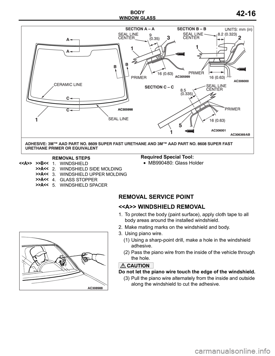
WINDOW GLASS
BODY42-16
Required Special Tool:
MB990480: Glass Holder
REMOVAL SERVICE POINT
.
<> WINDSHIELD REMOVAL
1. To protect the body (paint surface), apply cloth tape to all
body areas around the installed windshield.
2. Make mating marks on the windshield and body.
3. Using piano wire.
(1) Using a sharp-point drill, make a hole in the windshield
adhesive.
(2) Pass the piano wire from the inside of the vehicle through
the hole.
Do not let the piano wire touch the edge of the windshield.
(3) Pull the piano wire alternately from the inside and outside
along the windshield to cut the adhesive.
REMOVAL STEPS
<> >>B<<1. WINDSHIELD
>>A<<2. WINDSHIELD SIDE MOLDING
>>A<<3. WINDSHIELD UPPER MOLDING
>>A<<4. GLASS STOPPER
>>A<<5. WINDSHIELD SPACER
Page 1084 of 1500
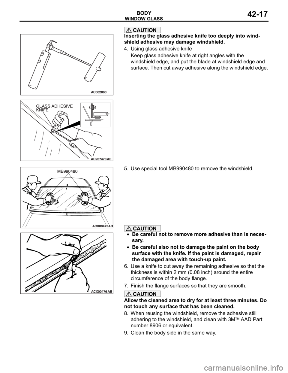
WINDOW GLASS
BODY42-17
Inserting the glass adhesive knife too deeply into wind-
shield adhesive may damage windshield.
4. Using glass adhesive knife
Keep glass adhesive knife at right angles with the
windshield edge, and put the blade at windshield edge and
surface. Then cut away adhesive along the windshield edge.
5. Use special tool MB990480 to remove the windshield.
Be careful not to remove more adhesive than is neces-
sary.
Be careful also not to damage the paint on the body
surface with the knife. If the paint is damaged, repair
the damaged area with touch-up paint.
6. Use a knife to cut away the remaining adhesive so that the
thickness is within 2 mm (0.08 inch) around the entire
circumference of the body flange.
7. Finish the flange surfaces so that they are smooth.
Allow the cleaned area to dry for at least three minutes. Do
not touch any surface that has been cleaned.
8. When reusing the windshield, remove the adhesive still
adhering to the windshield, and clean with 3M
AAD Part
number 8906 or equivalent.
9. Clean the body side in the same way.
Page 1085 of 1500

WINDOW GLASS
BODY42-18
INSTALLATION SERVICE POINTS
.
>>A<< WINDSHIELD SPACER/GLASS STOP-
PER/WINDSHIELD UPPER MOLDING/WIND-
SHIELD SIDE MOLDING INSTALLATION
Leave the degreased parts for 3 or more minutes to dry
well, before starting on the next step. Do not touch the
degreased parts.
1. Use 3M
AAD Part number 8906 or equivalent to degrease
the inside and outside of the windshield and the body
flanges.
2. Install the windshield spacer and glass stoppers to the
specified positions so that there are no adrift or warped
surfaces inside the windshield.
3. Install the windshield upper and side moldings to the
windshield.
.
Page 1086 of 1500
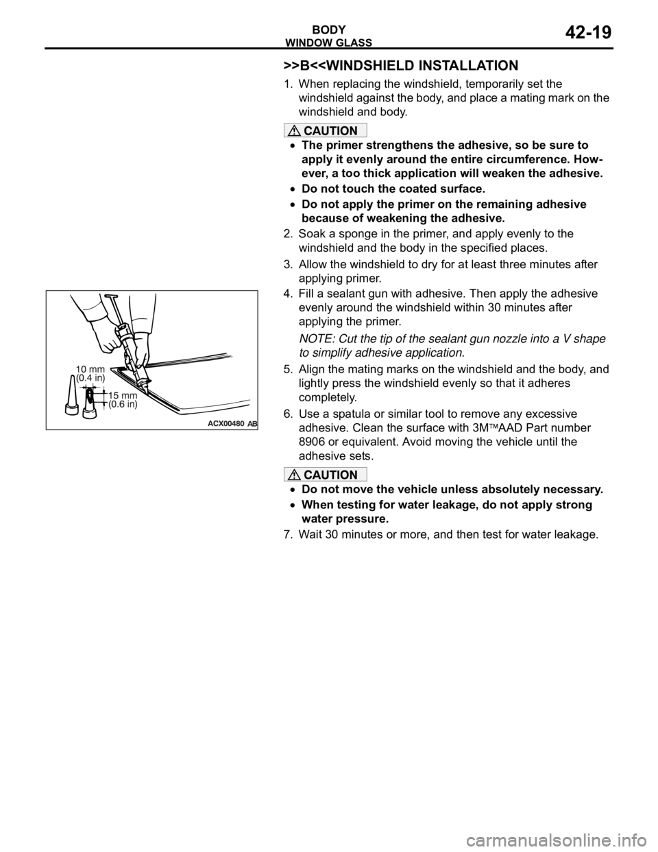
WINDOW GLASS
BODY42-19
>>B<
windshield against the body, and place a mating mark on the
windshield and body.
The primer strengthens the adhesive, so be sure to
apply it evenly around the entire circumference. How-
ever, a too thick application will weaken the adhesive.
Do not touch the coated surface.
Do not apply the primer on the remaining adhesive
because of weakening the adhesive.
2. Soak a sponge in the primer, and apply evenly to the
windshield and the body in the specified places.
3. Allow the windshield to dry for at least three minutes after
applying primer.
4. Fill a sealant gun with adhesive. Then apply the adhesive
evenly around the windshield within 30 minutes after
applying the primer.
NOTE: Cut the tip of the sealant gun nozzle into a V shape
to simplify adhesive application.
5. Align the mating marks on the windshield and the body, and
lightly press the windshield evenly so that it adheres
completely.
6. Use a spatula or similar tool to remove any excessive
adhesive. Clean the surface with 3M
AAD Part number
8906 or equivalent. Avoid moving the vehicle until the
adhesive sets.
Do not move the vehicle unless absolutely necessary.
When testing for water leakage, do not apply strong
water pressure.
7. Wait 30 minutes or more, and then test for water leakage.
Page 1087 of 1500
WINDOW GLASS
BODY42-20
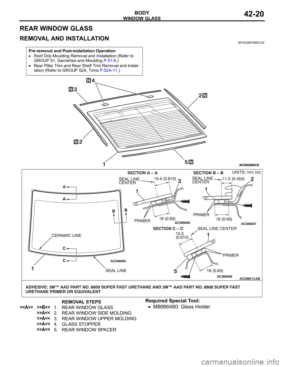
REAR WINDOW GLASS
REMOVAL AND INSTALLATIONM1422001600122
Required Special Tool:
MB990480: Glass Holder
Pre-removal and Post-installation Operation
Roof Drip Moulding Removal and Installation (Refer to
GROUP 51, Garnishes and Moulding P.51-8.)
Rear Pillar Trim and Rear Shelf Trim Removal and Instal-
lation (Refer to GROUP 52A, Trims P.52A-11.)
REMOVAL STEPS
<> >>B<<1. REAR WINDOW GLASS
>>A<<2. REAR WINDOW SIDE MOLDING
>>A<<3. REAR WINDOW UPPER MOLDING
>>A<<4. GLASS STOPPER
>>A<<5. REAR WINDOW SPACER