Battery MITSUBISHI 380 2005 Workshop Manual
[x] Cancel search | Manufacturer: MITSUBISHI, Model Year: 2005, Model line: 380, Model: MITSUBISHI 380 2005Pages: 1500, PDF Size: 47.87 MB
Page 1137 of 1500
KEYLESS ENTRY SYSTEM
BODY42-70
HOW TO REPLACE THE TRANSMITTER
BATTERY
BGBCHGFB
Do not allow water or dust to enter the inside of the trans-
mitter when it is opened. Also, do not touch the precision
electronic device.
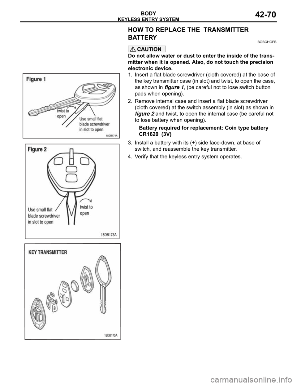
1. Insert a flat blade screwdriver (cloth covered) at the base of
the key transmitter case (in slot) and twist, to open the case,
as shown in figure 1, (be careful not to lose switch button
pads when opening).
2. Remove internal case and insert a flat blade screwdriver
(cloth covered) at the switch assembly (in slot) as shown in
figure 2 and twist, to open the internal case (be careful not
to lose battery when opening).
Battery required for replacement: Coin type battery
CR1620 (3V)
3. Install a battery with its (+) side face-down, at base of
switch, and reassemble the key transmitter.
4. Verify that the keyless entry system operates.
Page 1191 of 1500
MASTER CYLINDER ASSEMBLY AND BRAKE BOOSTER
BASIC BRAKE SYSTEM35A-26
MASTER CYLINDER ASSEMBLY AND BRAKE BOOSTER
REMOVAL AND INSTALLATIONM1351003700407
Required Special Tool:
MB991568: Push Rod Adjusting Socket
Pre-removal Operation
Strut Tower Bar Removal (Refer to GROUP 42, Strut
To w e r B a r P.42-12).
Battery Removal
Brake Fluid DrainingPost-installation Operation
Brake Fluid Supplying and Air Bleeding (Refer to
P.35A-16).
Brake Pedal Adjustment (Refer to P.35A-13).
Battery Installation
Strut Tower Bar Installation (Refer to GROUP 42, Strut
Tower Bar P.42-12).
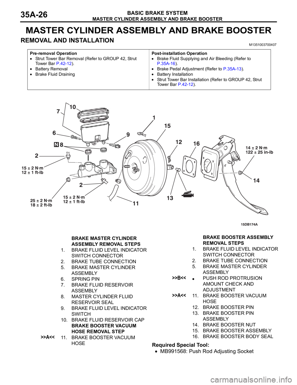
BRAKE MASTER CYLINDER
ASSEMBLY REMOVAL STEPS
1. BRAKE FLUID LEVEL INDICATOR
SWITCH CONNECTOR
2. BRAKE TUBE CONNECTION
5. BRAKE MASTER CYLINDER
ASSEMBLY
6. SPRING PIN
7. BRAKE FLUID RESERVOIR
ASSEMBLY
8. MASTER CYLINDER FLUID
RESERVOIR SEAL
9. BRAKE FLUID LEVEL INDICATOR
SWITCH
10. BRAKE FLUID RESERVOIR CAP
BRAKE BOOSTER VACUUM
HOSE REMOVAL STEP
>>A<<11. BRAKE BOOSTER VACUUM
HOSE BRAKE BOOSTER ASSEMBLY
REMOVAL STEPS
1. BRAKE FLUID LEVEL INDICATOR
SWITCH CONNECTOR
2. BRAKE TUBE CONNECTION
5. BRAKE MASTER CYLINDER
ASSEMBLY
>>B<
ADJUSTMENT
>>A<<11. BRAKE BOOSTER VACUUM
HOSE
12. BRAKE BOOSTER PIN
13. BRAKE BOOSTER PIN
ASSEMBLY
14. BRAKE BOOSTER NUT
15. BRAKE BOOSTER ASSEMBLY
16. BRAKE BOOSTER BODY SEAL
Page 1243 of 1500
PRECAUTIONS BEFORE SERVICE
GENERAL00-22
ENGINE MODEL STAMPING
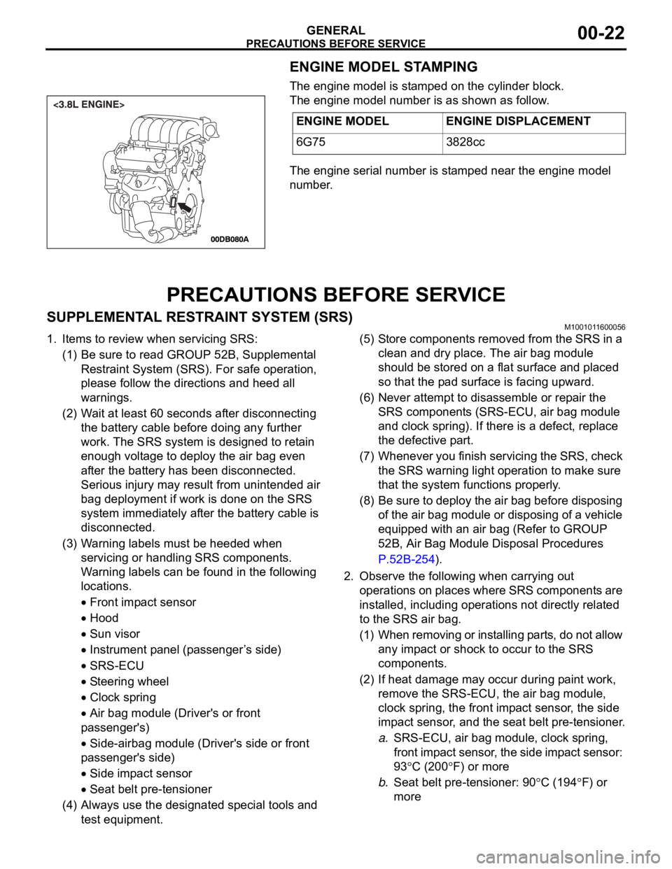
The engine model is stamped on the cylinder block.
The engine model number is as shown as follow.
The engine serial number is stamped near the engine model
number.
PRECAUTIONS BEFORE SERVICE
SUPPLEMENTAL RESTRAINT SYSTEM (SRS)M1001011600056
1. Items to review when servicing SRS:
(1) Be sure to read GROUP 52B, Supplemental
Restraint System (SRS). For safe operation,
please follow the directions and heed all
warnings.
(2) Wait at least 60 seconds after disconnecting
the battery cable before doing any further
work. The SRS system is designed to retain
enough voltage to deploy the air bag even
after the battery has been disconnected.
Serious injury may result from unintended air
bag deployment if work is done on the SRS
system immediately after the battery cable is
disconnected.
(3) Warning labels must be heeded when
servicing or handling SRS components.
Warning labels can be found in the following
locations.
Front impact sensor
Hood
Sun visor
Instrument panel (passenger ’s side)
SRS-ECU
Steering wheel
Clock spring
Air bag module (Driver's or front
passenger's)
Side-airbag module (Driver's side or front
passenger's side)
Side impact sensor
Seat belt pre-tensioner
(4) Always use the designated special tools and
test equipment.(5) Store components removed from the SRS in a
clean and dry place. The air bag module
should be stored on a flat surface and placed
so that the pad surface is facing upward.
(6) Never attempt to disassemble or repair the
SRS components (SRS-ECU, air bag module
and clock spring). If there is a defect, replace
the defective part.
(7) Whenever you finish servicing the SRS, check
the SRS warning light operation to make sure
that the system functions properly.
(8) Be sure to deploy the air bag before disposing
of the air bag module or disposing of a vehicle
equipped with an air bag (Refer to GROUP
52B, Air Bag Module Disposal Procedures
P.52B-254).
2. Observe the following when carrying out
operations on places where SRS components are
installed, including operations not directly related
to the SRS air bag.
(1) When removing or installing parts, do not allow
any impact or shock to occur to the SRS
components.
(2) If heat damage may occur during paint work,
remove the SRS-ECU, the air bag module,
clock spring, the front impact sensor, the side
impact sensor, and the seat belt pre-tensioner.
a.SRS-ECU, air bag module, clock spring,
front impact sensor, the side impact sensor:
93
C (200F) or more
b.Seat belt pre-tensioner: 90
C (194F) or
more ENGINE MODEL ENGINE DISPLACEMENT
6G75 3828cc
Page 1245 of 1500
PRECAUTIONS BEFORE SERVICE
GENERAL00-24
SERVICING ELECTRICAL SYSTEMM1001011900057
Battery posts, terminals and related accessories con-
tain lead and lead compounds. WASH HANDS AFTER
HANDLING.
1. Note the following before proceeding with working on the
electrical system.
Never perform unauthorized modifications to any electrical
device or wiring. Such modifications might lead to a vehicle
malfunction, over-capacity or short-circuit that could result in
a fire in the vehicle.
Before connecting or disconnecting the negative bat-
tery cable, be sure to turn the ignition switch to the
"LOCK" (OFF) position and turn off the lights (If this is
not done, there is the possibility of semiconductor
parts being damaged).
After completion of the work (and the negative battery
terminals is connected), warm up the engine and allow
it to idle for approximately 10 minutes under the condi-
tions described below in order to stabilize engine con-
trol conditions, and then check to be sure that the idle
is satisfactory.
Engine coolant temperature: 85 to 95C (185 to
203
F)
Lights and all accessories: OFF
Transaxle: "N" or "P" position
Steering wheel: straight-forward position
2. When servicing the electrical system, disconnect the
negative cable terminal from the battery.
VEHICLE WASHINGM1001012000057
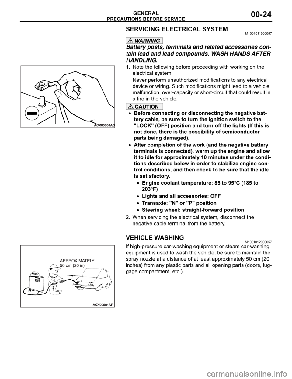
If high-pressure car-washing equipment or steam car-washing
equipment is used to wash the vehicle, be sure to maintain the
spray nozzle at a distance of at least approximately 50 cm (20
inches) from any plastic parts and all opening parts (doors, lug-
gage compartment, etc.).
Page 1272 of 1500
MAINTENANCE SERVICE
GENERAL00-51
18. SUSPENSION SYSTEM (INSPECT FOR
LOOSENESS AND DAMAGE)
M1001009600048
Visually inspect the front/rear suspension components for dete-
rioration and damage. Re-tighten the front/rear suspension
components retaining bolts to specified torque.
19. SRS AIR BAG (INSPECT FOR SRS SYSTEM)M1001003700326
The entire SRS including air bag and pre-tensioner seat belt
must be inspected by an authorized MITSUBISHI MOTORS
dealer 10 years.
SRS WARNING LIGHT CHECK
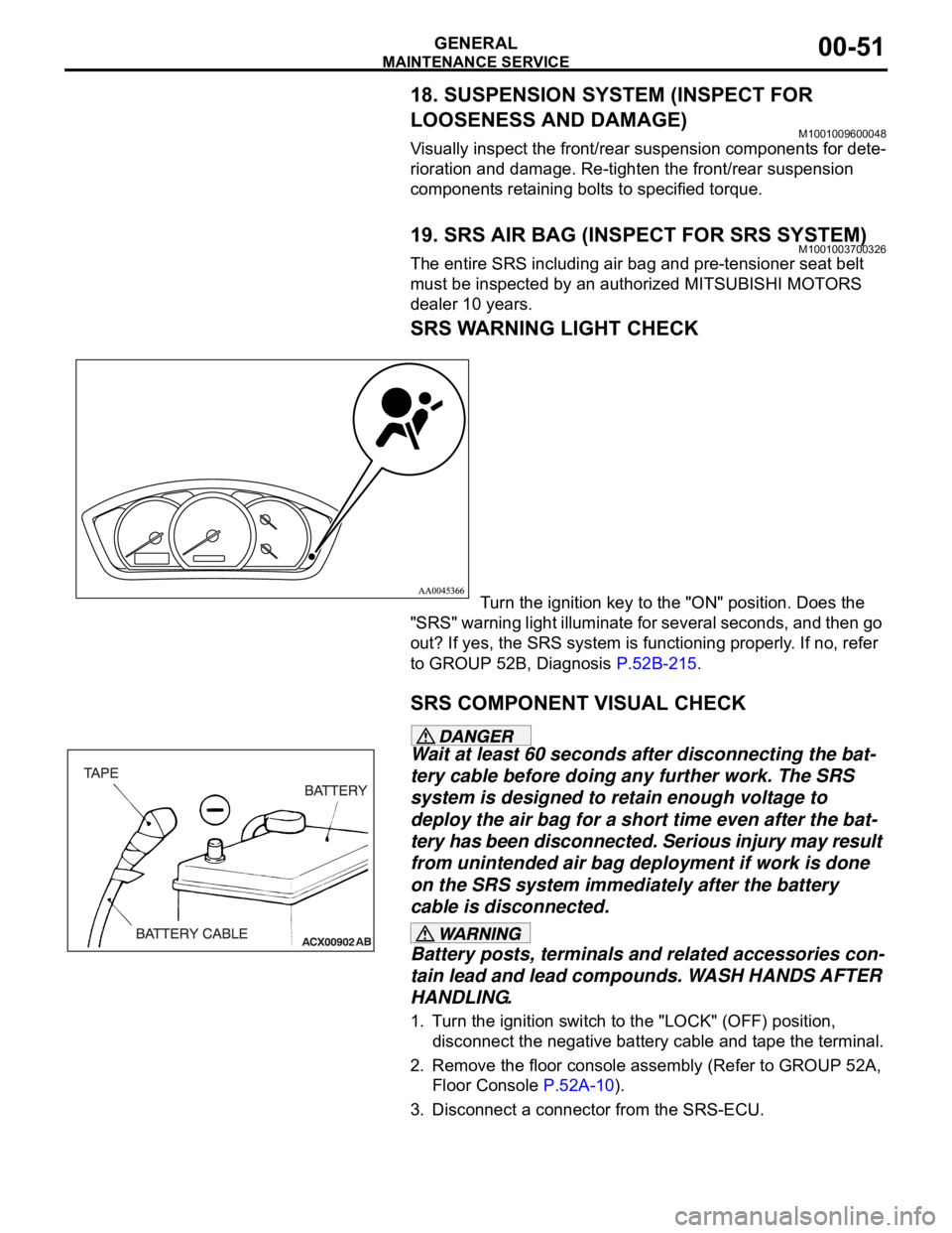
Turn the ignition key to the "ON" position. Does the
"SRS" warning light illuminate for several seconds, and then go
out? If yes, the SRS system is functioning properly. If no, refer
to GROUP 52B, Diagnosis P.52B-215.
SRS COMPONENT VISUAL CHECK
Wait at least 60 seconds after disconnecting the bat-
tery cable before doing any further work. The SRS
system is designed to retain enough voltage to
deploy the air bag for a short time even after the bat-
tery has been disconnected. Serious injury may result
from unintended air bag deployment if work is done
on the SRS system immediately after the battery
cable is disconnected.
Battery posts, terminals and related accessories con-
tain lead and lead compounds. WASH HANDS AFTER
HANDLING.
1. Turn the ignition switch to the "LOCK" (OFF) position,
disconnect the negative battery cable and tape the terminal.
2. Remove the floor console assembly (Refer to GROUP 52A,
Floor Console P.52A-10).
3. Disconnect a connector from the SRS-ECU.
Page 1283 of 1500
TRACTION CONTROL SYSTEM (TCL) DIAGNOSIS
TRACTION CONTROL SYSTEM (TCL)13C-4
To prevent damage to diagnostic tool MB991958, always
turn the ignition switch to the "LOCK" (OFF) position
before connecting or disconnecting diagnostic tool
MB991958.
1. Ensure that the ignition switch is at the "LOCK" (OFF)
position.
2. Start up the personal computer.
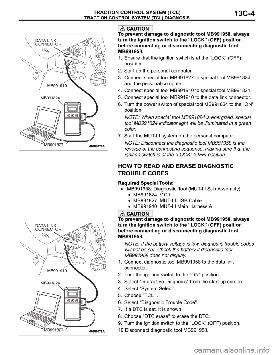
3. Connect special tool MB991827 to special tool MB991824
and the personal computer.
4. Connect special tool MB991910 to special tool MB991824.
5. Connect special tool MB991910 to the data link connector.
6. Turn the power switch of special tool MB991824 to the "ON"
position.
NOTE: When special tool MB991824 is energized, special
tool MB991824 indicator light will be illuminated in a green
color.
7. Start the MUT-III system on the personal computer.
NOTE: Disconnect the diagnostic tool MB991958 is the
reverse of the connecting sequence, making sure that the
ignition switch is at the "LOCK" (OFF) position.
HOW TO READ AND ERASE DIAGNOSTIC
TROUBLE CODES
Required Special Tools:
MB991958: Diagnostic Tool (MUT-III Sub Assembly)
MB991824: V.C.I.
MB991827: MUT-III USB Cable
MB991910: MUT-III Main Harness A
To prevent damage to diagnostic tool MB991958, always
turn the ignition switch to the "LOCK" (OFF) position
before connecting or disconnecting diagnostic tool
MB991958.
NOTE: If the battery voltage is low, diagnostic trouble codes
will not be set. Check the battery if diagnostic tool
MB991958 does not display.
1. Connect diagnostic tool MB991958 to the data link
connector.
2. Turn the ignition switch to the "ON" position.
3. Select "Interactive Diagnosis" from the start-up screen.
4. Select "System Select".
5. Choose "TCL" .
6. Select "Diagnostic Trouble Code".
7. If a DTC is set, it is shown.
8. Choose "DTC erase" to erase the DTC.
9. Turn the ignition switch to the "LOCK" (OFF) position.
10.Disconnect diagnostic tool MB991958.
Page 1315 of 1500

TRACTION CONTROL SYSTEM (TCL) DIAGNOSIS
TRACTION CONTROL SYSTEM (TCL)13C-36
DATA LIST REFERENCE TABLEM1136003500071
NOTE: If the ABS-8 ECU or the active wheel
speed sensor are disconnected, or if the wiring is
an open/ short circuit, the ABS 8 ECU will shut
off power supply to the respective wheel speed
sensor. All other wheel speed sensors will oper-
ate normally. To restore the power supply, the
ignition switch must be turned to the "OFF" posi-
tion then to the "ON" position again.The following items can be read by the diagnostic
tool from the ABS/TCL-ECU input data. (Refer to
P.13C-3).
NOTE: Since the TCL is controlled with the same ABS/TCL-ECU used to control the ABS, the stoplight switch
check item (No.6) used only for the ABS also appear.MUT-III
DIAGNOSTI
C TOOL
DISPLAYITEM
NO.CHECK ITEM CHECKING REQUIREMENTS NORMAL
VA L U E
FL wheel
speed sensor01 Front left wheel speed sensor Drive the vehicle Vehicle speeds
displayed on the
speedometer
and diagnostic
tool are identical. FR wheel
speed sensor02 Front right wheel speed sensor
RL wheel
speed sensor03 Rear left wheel speed sensor
RR wheel
speed sensor04 Rear right left wheel speed
sensor
Power supply
voltage05 ABS/TCL-ECU power supply
voltageIgnition switch power supply
voltageBattery positive
voltage
Stoplamp
switch
(input)*06 Stoplamp switch Depress the brake pedal. ON
Release the brake pedal. OFF
Stoplamp
switch*13 Stoplamp switch Depress the brake pedal. ON
Release the brake pedal. OFF
Pump motor 21 Pump motor When the ABS outputs the
operation permission signal
during drivingON
When the ABS outputs the
operation permission signal
during drivingOFF
Valve relay 30 Valve relayWhen the ABS outputs the
operation permission signal
during drivingON
When the ABS outputs the
operation permission signal
during drivingOFF
TCL mode 35 TCL operation When the TCL outputs the
operation permission signal
during drivingON
When the TCL outputs the
operation inhibition signal
during drivingOFF
Page 1317 of 1500
TRACTION CONTROL SYSTEM (TCL) DIAGNOSIS
TRACTION CONTROL SYSTEM (TCL)13C-38
CHECK AT ABS/TCL-ECU CONNECTOR: A-02
RESISTANCE AND TERMINAL VOLTAGE
M1136003800072
RESISTANCE AND TERMINAL VOLTAGE CHECK
CHART
.
Required Special Tools:
MB991219: Inspection Test Harness
MB991223: Harness Set
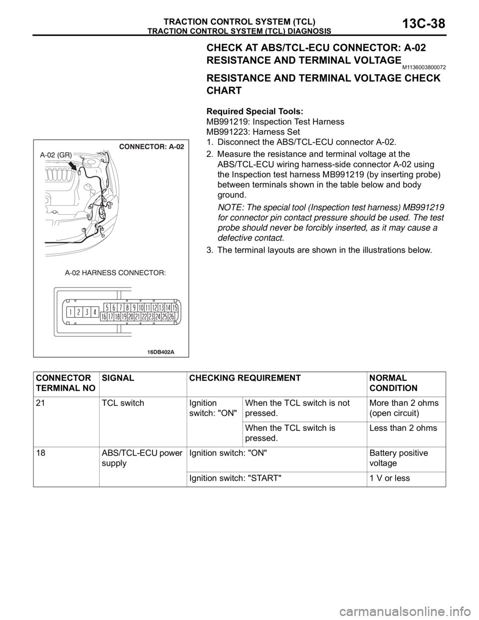
1. Disconnect the ABS/TCL-ECU connector A-02.
2. Measure the resistance and terminal voltage at the
ABS/TCL-ECU wiring harness-side connector A-02 using
the Inspection test harness MB991219 (by inserting probe)
between terminals shown in the table below and body
ground.
NOTE: The special tool (Inspection test harness) MB991219
for connector pin contact pressure should be used. The test
probe should never be forcibly inserted, as it may cause a
defective contact.
3. The terminal layouts are shown in the illustrations below.
CONNECTOR
TERMINAL NOSIGNAL CHECKING REQUIREMENT NORMAL
CONDITION
21 TCL switch Ignition
switch: "ON" When the TCL switch is not
pressed.More than 2 ohms
(open circuit)
When the TCL switch is
pressed.Less than 2 ohms
18 ABS/TCL-ECU power
supplyIgnition switch: "ON" Battery positive
voltage
Ignition switch: "START" 1 V or less
Page 1343 of 1500
AUTO-CRUISE CONTROL
ENGINE AND EMISSION CONTROL17-12
To prevent damage to Diagnostic Tool MB991958, always
turn the ignition switch to the "LOCK" (OFF) position
before connecting or disconnecting Diagnostic Tool
MB991958.
1. Ensure that the ignition switch is at the "LOCK" (OFF)
position.
2. Start up the personal computer.
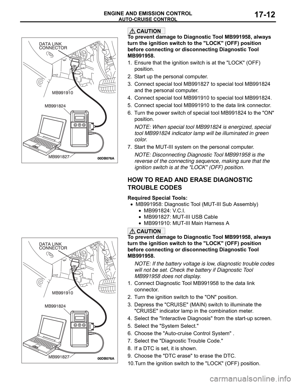
3. Connect special tool MB991827 to special tool MB991824
and the personal computer.
4. Connect special tool MB991910 to special tool MB991824.
5. Connect special tool MB991910 to the data link connector.
6. Turn the power switch of special tool MB991824 to the "ON"
position.
NOTE: When special tool MB991824 is energized, special
tool MB991824 indicator lamp will be illuminated in green
color.
7. Start the MUT-III system on the personal computer.
NOTE: Disconnecting Diagnostic Tool MB991958 is the
reverse of the connecting sequence, making sure that the
ignition switch is at the "LOCK" (OFF) position.
HOW TO READ AND ERASE DIAGNOSTIC
TROUBLE CODES
Required Special Tools:
MB991958: Diagnostic Tool (MUT-III Sub Assembly)
MB991824: V.C.I.
MB991827: MUT-III USB Cable
MB991910: MUT-III Main Harness A
To prevent damage to Diagnostic Tool MB991958, always
turn the ignition switch to the "LOCK" (OFF) position
before connecting or disconnecting Diagnostic Tool
MB991958.
NOTE: If the battery voltage is low, diagnostic trouble codes
will not be set. Check the battery if Diagnostic Tool
MB991958 does not display.
1. Connect Diagnostic Tool MB991958 to the data link
connector.
2. Turn the ignition switch to the "ON" position.
3. Depress the "CRUISE" (MAIN) switch to illuminate the
"CRUISE" indicator lamp in the combination meter.
4. Select the "Interactive Diagnosis" from the start-up screen.
5. Select the "System Select."
6. Choose the "Auto-cruise Control System" .
7. Select the "Diagnostic Trouble Code."
8. If a DTC is set, it is shown.
9. Choose the "DTC erase" to erase the DTC.
10.Turn the ignition switch to the "LOCK" (OFF) position.
Page 1348 of 1500
AUTO-CRUISE CONTROL
ENGINE AND EMISSION CONTROL17-17
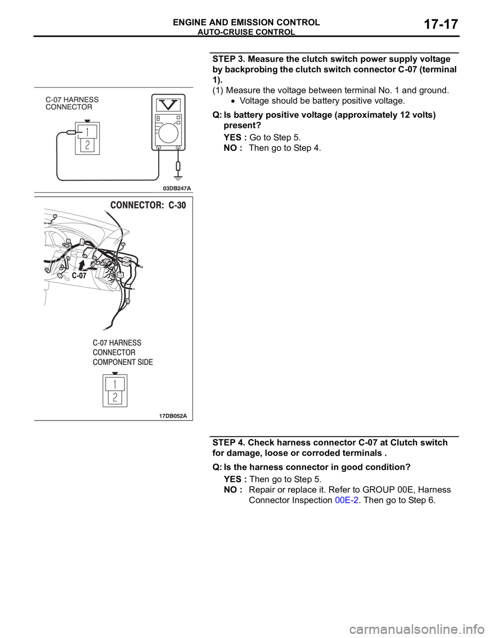
STEP 3. Measure the clutch switch power supply voltage
by backprobing the clutch switch connector C-07 (terminal
1).
(1) Measure the voltage between terminal No. 1 and ground.
Voltage should be battery positive voltage.
Q: Is battery positive voltage (approximately 12 volts)
present?
YES : Go to Step 5.
NO : Then go to Step 4.
STEP 4. Check harness connector C-07 at Clutch switch
for damage, loose or corroded terminals .
Q: Is the harness connector in good condition?
YES : Then go to Step 5.
NO : Repair or replace it. Refer to GROUP 00E, Harness
Connector Inspection 00E-2. Then go to Step 6.