Battery MITSUBISHI 380 2005 Workshop Manual
[x] Cancel search | Manufacturer: MITSUBISHI, Model Year: 2005, Model line: 380, Model: MITSUBISHI 380 2005Pages: 1500, PDF Size: 47.87 MB
Page 1474 of 1500

AUTOMATIC TRANSMISSION DIAGNOSIS
AUTOMATIC TRANSMISSION23A-15
To prevent damage to diagnostic tool MB991958, always
turn the ignition switch to the "LOCK" (OFF) position
before connecting or disconnecting diagnostic tool
MB991958.
NOTE: If the battery voltage is low, diagnostic trouble codes
will not be set. Check the battery if diagnostic tool
MB991958 does not display.
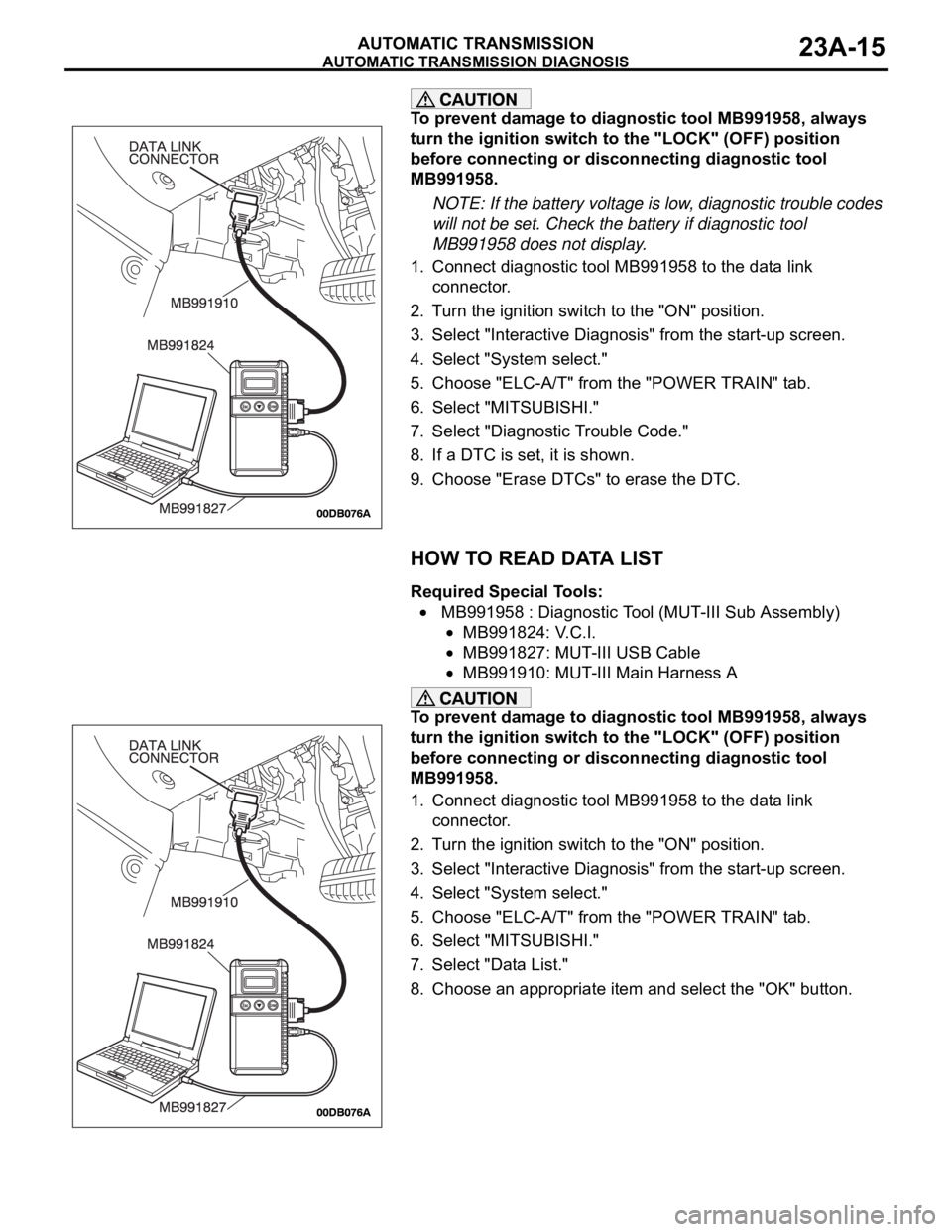
1. Connect diagnostic tool MB991958 to the data link
connector.
2. Turn the ignition switch to the "ON" position.
3. Select "Interactive Diagnosis" from the start-up screen.
4. Select "System select."
5. Choose "ELC-A/T" from the "POWER TRAIN" tab.
6. Select "MITSUBISHI."
7. Select "Diagnostic Trouble Code."
8. If a DTC is set, it is shown.
9. Choose "Erase DTCs" to erase the DTC.
HOW TO READ DATA LIST
Required Special Tools:
MB991958 : Diagnostic Tool (MUT-III Sub Assembly)
MB991824: V.C.I.
MB991827: MUT-III USB Cable
MB991910: MUT-III Main Harness A
To prevent damage to diagnostic tool MB991958, always
turn the ignition switch to the "LOCK" (OFF) position
before connecting or disconnecting diagnostic tool
MB991958.
1. Connect diagnostic tool MB991958 to the data link
connector.
2. Turn the ignition switch to the "ON" position.
3. Select "Interactive Diagnosis" from the start-up screen.
4. Select "System select."
5. Choose "ELC-A/T" from the "POWER TRAIN" tab.
6. Select "MITSUBISHI."
7. Select "Data List."
8. Choose an appropriate item and select the "OK" button.
Page 1476 of 1500

AUTOMATIC TRANSMISSION DIAGNOSIS
AUTOMATIC TRANSMISSION23A-17
To prevent damage to diagnostic tool MB991958, always
turn the ignition switch to the "LOCK" (OFF) position
before connecting or disconnecting diagnostic tool
MB991958.
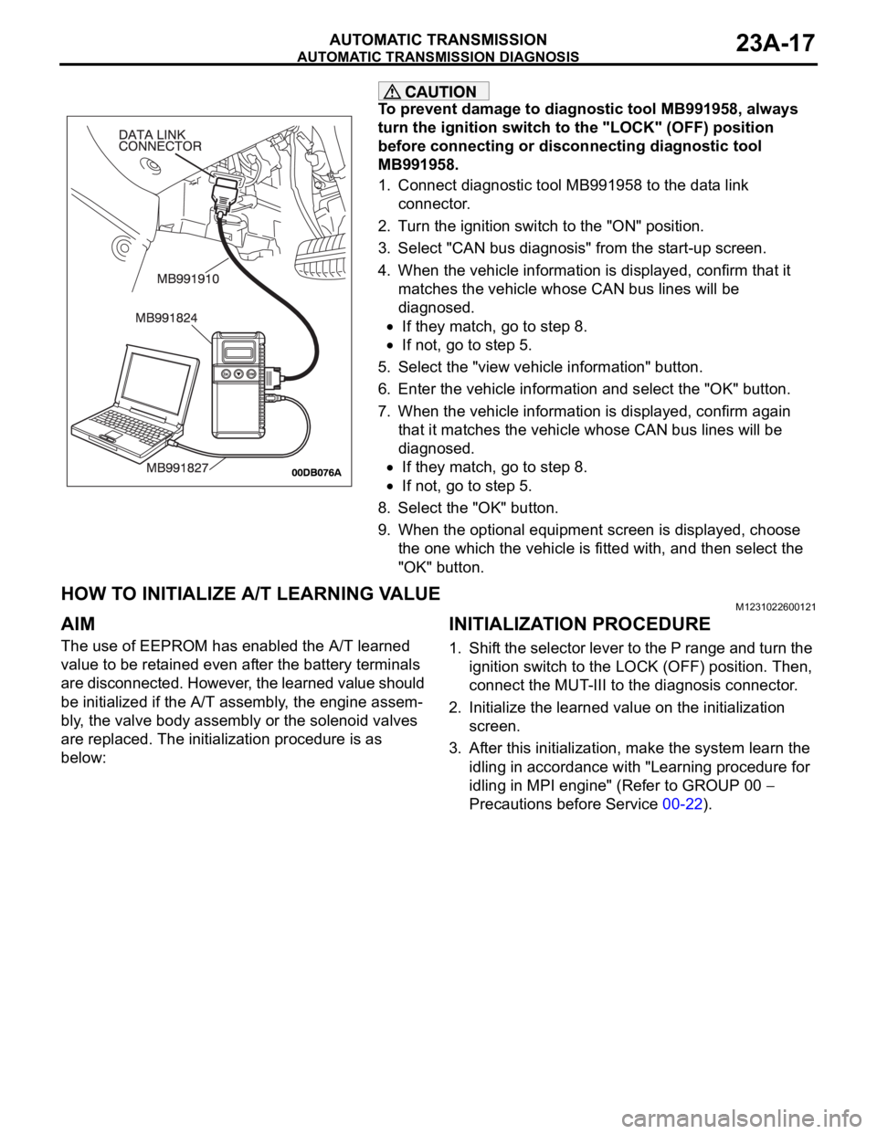
1. Connect diagnostic tool MB991958 to the data link
connector.
2. Turn the ignition switch to the "ON" position.
3. Select "CAN bus diagnosis" from the start-up screen.
4. When the vehicle information is displayed, confirm that it
matches the vehicle whose CAN bus lines will be
diagnosed.
If they match, go to step 8.
If not, go to step 5.
5. Select the "view vehicle information" button.
6. Enter the vehicle information and select the "OK" button.
7. When the vehicle information is displayed, confirm again
that it matches the vehicle whose CAN bus lines will be
diagnosed.
If they match, go to step 8.
If not, go to step 5.
8. Select the "OK" button.
9. When the optional equipment screen is displayed, choose
the one which the vehicle is fitted with, and then select the
"OK" button.
HOW TO INITIALIZE A/T LEARNING VALUEM1231022600121
AIM
The use of EEPROM has enabled the A/T learned
value to be retained even after the battery terminals
are disconnected. However, the learned value should
be initialized if the A/T assembly, the engine assem-
bly, the valve body assembly or the solenoid valves
are replaced. The initialization procedure is as
below:
INITIALIZATION PROCEDURE
1. Shift the selector lever to the P range and turn the
ignition switch to the LOCK (OFF) position. Then,
connect the MUT-III to the diagnosis connector.
2. Initialize the learned value on the initialization
screen.
3. After this initialization, make the system learn the
idling in accordance with "Learning procedure for
idling in MPI engine" (Refer to GROUP 00
Precautions before Service 00-22).