Battery MITSUBISHI 380 2005 Workshop Manual
[x] Cancel search | Manufacturer: MITSUBISHI, Model Year: 2005, Model line: 380, Model: MITSUBISHI 380 2005Pages: 1500, PDF Size: 47.87 MB
Page 988 of 1500
CHARGING SYSTEM
ENGINE ELECTRICAL16-11
11.Increase the engine speed to 2,500 r/min.
12.Read the value displayed on the voltmeter when
the current output by the alternator becomes 10 A
or less.
13.If the voltage reading conforms to the value in the
voltage regulation table, then the voltage regulator
is operating normally.
If the voltage is outside the standard value, there
is a malfunction of the voltage regulator or the
alternator (Refer to the following table).14.After the test, lower the engine speed to idle.
15.Turn the ignition switch to the "LOCK" (OFF)
position.
16.Disconnect the engine tachometer or diagnostic
tool .
17.Disconnect the negative battery cable.
18.Disconnect the ammeter and voltmeter.
19.Connect the negative battery cable.
20.Run the engine for 10 minutes at an idle.
VOLTAGE REGULATION TABLE
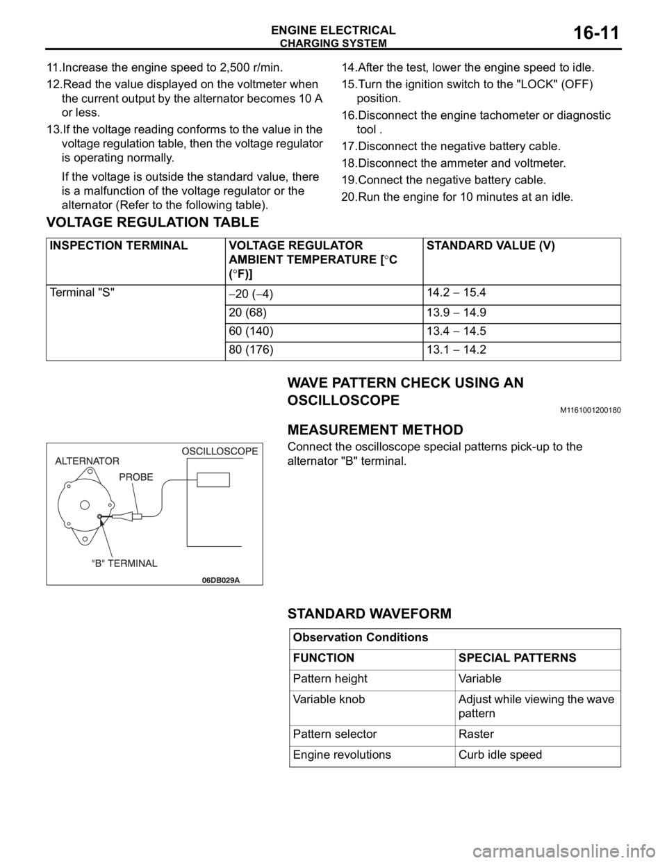
WAVE PATTERN CHECK USING AN
OSCILLOSCOPE
M1161001200180.
MEASUREMENT METHOD
Connect the oscilloscope special patterns pick-up to the
alternator "B" terminal.
.
STANDARD WAVEFORM
INSPECTION TERMINAL VOLTAGE REGULATOR
AMBIENT TEMPERATURE [
C
(
F)]STANDARD VALUE (V)
Te r m i n a l " S "
20 (4)14.2 15.4
20 (68) 13.9
14.9
60 (140) 13.4
14.5
80 (176) 13.1
14.2
Observation Conditions
FUNCTION SPECIAL PATTERNS
Pattern height Variable
Variable knob Adjust while viewing the wave
pattern
Pattern selector Raster
Engine revolutions Curb idle speed
Page 989 of 1500
CHARGING SYSTEM
ENGINE ELECTRICAL16-12
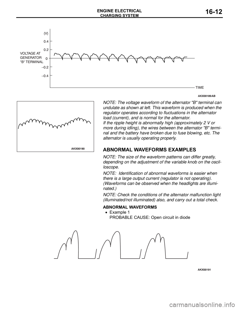
NOTE: The voltage waveform of the alternator "B" terminal can
undulate as shown at left. This waveform is produced when the
regulator operates according to fluctuations in the alternator
load (current), and is normal for the alternator.
If the ripple height is abnormally high (approximately 2 V or
more during idling), the wires between the alternator "B" termi-
nal and the battery have broken due to fuse blowing, etc. The
alternator is usually operating properly.
.
ABNORMAL WAVEFORMS EXAMPLES
NOTE: The size of the waveform patterns can differ greatly,
depending on the adjustment of the variable knob on the oscil-
loscope.
NOTE: Identification of abnormal waveforms is easier when
there is a large output current (regulator is not operating).
(Waveforms can be observed when the headlights are illumi-
nated.)
NOTE: Check the conditions of the alternator malfunction light
(illuminated/not illuminated) also, and carry out a total check.
ABNORMAL WAVEFORMS
Example 1
PROBABLE CAUSE: Open circuit in diode
Page 998 of 1500
STARTING SYSTEM
ENGINE ELECTRICAL16-21
STARTING SYSTEM DIAGNOSISM1162000700293
TROUBLESHOOTING HINTS
The starter motor does not operate at all.
Battery posts, terminals and related accessories con-
tain lead and lead compounds. WASH HANDS AFTER
HANDLING.
Check the starter (coil).
Check for poor contact at the battery terminals and
starter.
Check the transmission range switch.
The starter motor doesn't stop
Check the starter (magnetic switch).
TROUBLESHOOTING GUIDE
The starting system troubleshooting guide is shown in the fol-
lowing steps.
Battery posts, terminals and related accessories con-
tain lead and lead compounds. WASH HANDS AFTER
HANDLING.
STEP 1.
Q: Is the battery in good condition? (Refer to GROUP 54A,
Chassis Electrical
Battery On-vehicle Service
Battery Check P.54A-5.)
YES : Go to Step 2.
NO : Charge or replace the battery.
STEP 2.
Disconnect the starter motor S (solenoid) terminal connec-
tor.
Using a jumper wire, apply battery positive voltage to the
starter motor S (solenoid) terminal.
Check the engine condition.
OK: Turns normally
Q: Dose the starter motor operate normally?
YES :
Check the ignition switch (Refer to GROUP 54A,
Chassis Electrical
Ignition Switch Ignition
Switch
Inspection P.54A-44.)
Check the transmission range switch. (Refer to
GROUP 23A, Automatic Transaxle
On-vehicle
Service
Essential Service Transmission Range
Switch Check P.23A-294.)
Check the wire between the battery and starter
motor S (solenoid) terminal.
NO : Go to Step 3.
Page 999 of 1500
STARTING SYSTEM
ENGINE ELECTRICAL16-22
STEP 3.
Check the cable between starter B (battery) terminal and
battery positive terminal for connection and continuity.
Q: Is the starter cable in good condition?
YES : Go to Step 4.
NO : Repair or replace the cable.
STEP 4.
Check the connection and the continuity of the cable
between the starter motor body and the negative battery
terminal.
Q: Is the ground wire in good condition?
YES : Go to Step 5.
NO : Repair or replace the cable.
STEP 5.
Q: Is the starter motor in good condition? (Refer to Starting
System
Starter Motor Assembly Inspection P.16-17.)
YES : Excessive rotational resistance of the engine.
NO : Replace the starter motor.
Page 1001 of 1500
Page 1002 of 1500
STARTING SYSTEM
ENGINE ELECTRICAL16-25
.
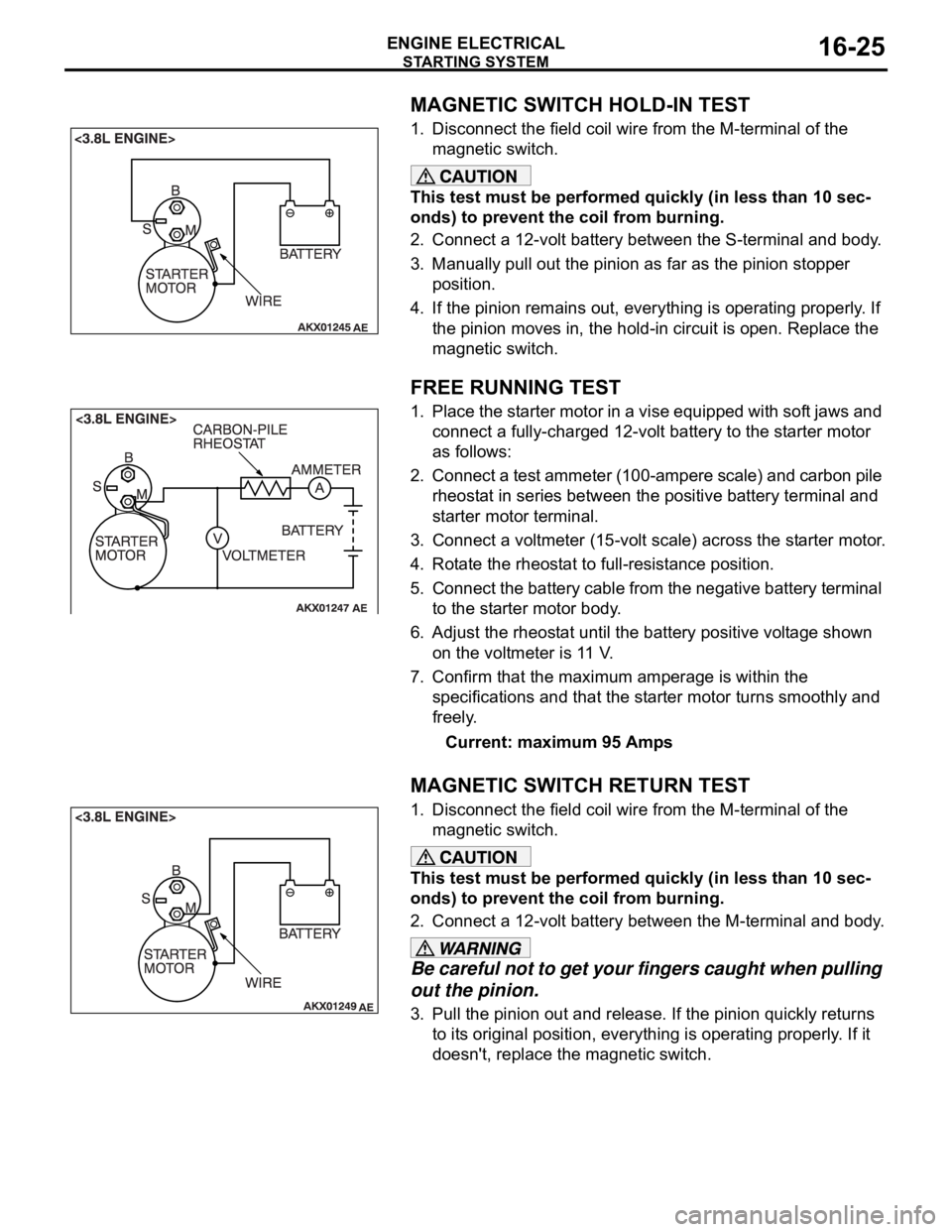
MAGNETIC SWITCH HOLD-IN TEST
1. Disconnect the field coil wire from the M-terminal of the
magnetic switch.
This test must be performed quickly (in less than 10 sec-
onds) to prevent the coil from burning.
2. Connect a 12-volt battery between the S-terminal and body.
3. Manually pull out the pinion as far as the pinion stopper
position.
4. If the pinion remains out, everything is operating properly. If
the pinion moves in, the hold-in circuit is open. Replace the
magnetic switch.
.
FREE RUNNING TEST
1. Place the starter motor in a vise equipped with soft jaws and
connect a fully-charged 12-volt battery to the starter motor
as follows:
2. Connect a test ammeter (100-ampere scale) and carbon pile
rheostat in series between the positive battery terminal and
starter motor terminal.
3. Connect a voltmeter (15-volt scale) across the starter motor.
4. Rotate the rheostat to full-resistance position.
5. Connect the battery cable from the negative battery terminal
to the starter motor body.
6. Adjust the rheostat until the battery positive voltage shown
on the voltmeter is 11 V.
7. Confirm that the maximum amperage is within the
specifications and that the starter motor turns smoothly and
freely.
Current: maximum 95 Amps
.
MAGNETIC SWITCH RETURN TEST
1. Disconnect the field coil wire from the M-terminal of the
magnetic switch.
This test must be performed quickly (in less than 10 sec-
onds) to prevent the coil from burning.
2. Connect a 12-volt battery between the M-terminal and body.
Be careful not to get your fingers caught when pulling
out the pinion.
3. Pull the pinion out and release. If the pinion quickly returns
to its original position, everything is operating properly. If it
doesn't, replace the magnetic switch.
Page 1015 of 1500

SPECIFICATIONS
ENGINE ELECTRICAL16-38
SPECIFICATIONS
FASTENER TIGHTENING SPECIFICATIONSM1161002100506
GENERAL SPECIFICATIONSM1161000200411
ITEM SPECIFICATION
Charging system
Alternator bracket bolt49
9 Nm (36 7 ft-lb)
Alternator bolt49
9 Nm (36 7 ft-lb)
Alternator terminal nut12
2 Nm (102 22 in-lb)
Ignition system
Camshaft position sensor bolt 11
1 Nm (98 8 in-lb)
Crankshaft position sensor bolt 9.0
1.0 Nm (80 9 in-lb)
Ignition coil bolt 10
2 Nm (89 17 in-lb)
Knock sensor 23
2 Nm (17 1 ft-lb)
Spark plug 25
4 Nm (18 3 ft-lb)
Starting system
Starter bolt 30
3 Nm (23 2 ft-lb)
Starter cover bolt 4.9
1.0 Nm (44 8 in-lb)
Starter terminal nut 12
2 Nm (102 22 in-lb)
ITEMS SPECIFICATIONS
Alternator
Type Positive battery positive voltage sensing
Identification number
Part No. MN180394
Rated output V/A 12/110
Voltage regulator Electronic built-in type
Starter Motor
Type Reduction drive with planetary gear
Identification number M000T31172
Part No. 1810A090
Rated output kW/V 1.2/12
Number of pinion teeth 8
Ignition Coil
Type Molded 6 coil
Spark Plugs
BOSCH FR8DI30
Page 1022 of 1500
TRANSAXLE MOUNTING
POWER PLANT MOUNT32-5
TRANSAXLE MOUNTING
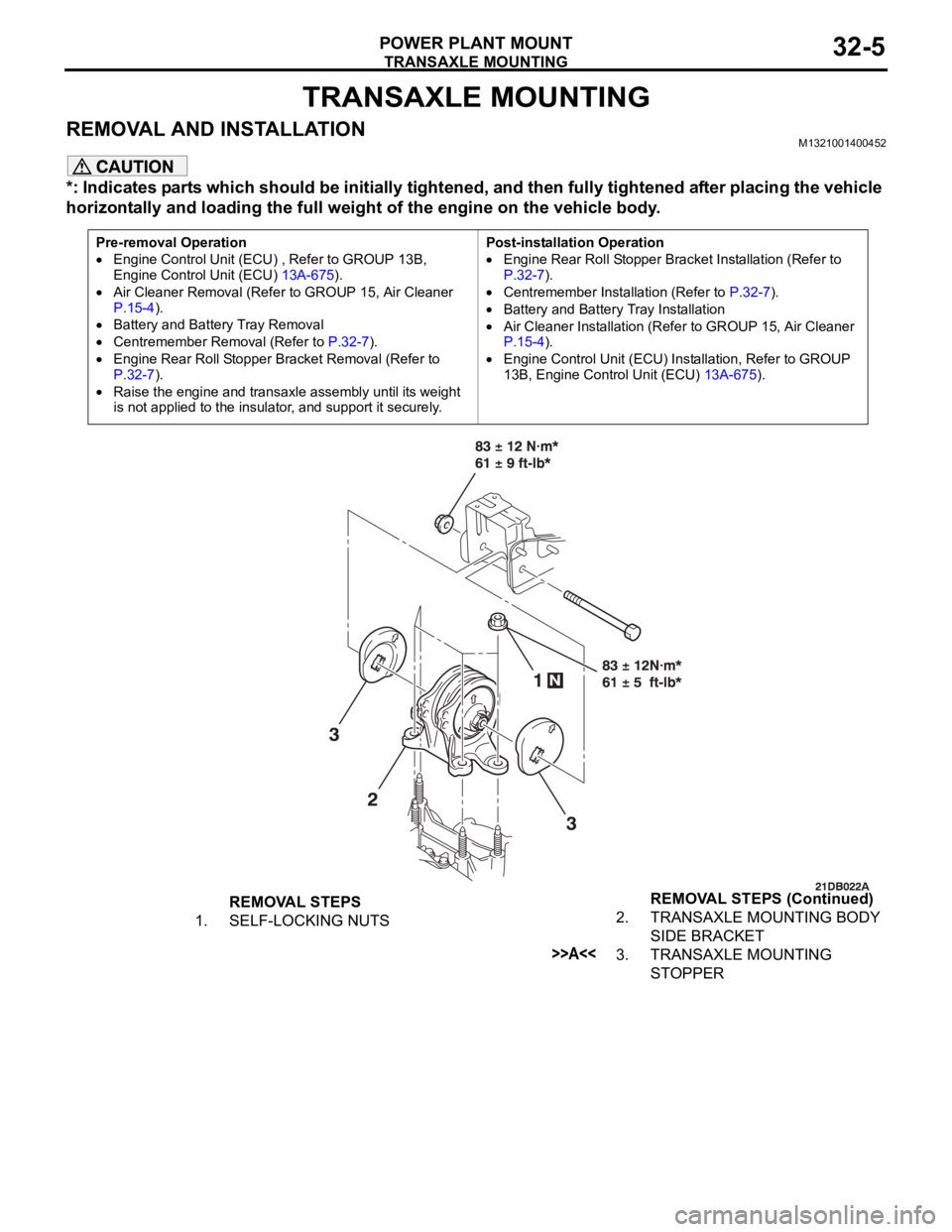
REMOVAL AND INSTALLATIONM1321001400452
*: Indicates parts which should be initially tightened, and then fully tightened after placing the vehicle
horizontally and loading the full weight of the engine on the vehicle body.
Pre-removal Operation
Engine Control Unit (ECU) , Refer to GROUP 13B,
Engine Control Unit (ECU) 13A-675).
Air Cleaner Removal (Refer to GROUP 15, Air Cleaner
P.15-4).
Battery and Battery Tray Removal
Centremember Removal (Refer to P.32-7).
Engine Rear Roll Stopper Bracket Removal (Refer to
P.32-7).
Raise the engine and transaxle assembly until its weight
is not applied to the insulator, and support it securely.Post-installation Operation
Engine Rear Roll Stopper Bracket Installation (Refer to
P.32-7).
Centremember Installation (Refer to P.32-7).
Battery and Battery Tray Installation
Air Cleaner Installation (Refer to GROUP 15, Air Cleaner
P.15-4).
Engine Control Unit (ECU) Installation, Refer to GROUP
13B, Engine Control Unit (ECU) 13A-675).
REMOVAL STEPS
1. SELF-LOCKING NUTS2. TRANSAXLE MOUNTING BODY
SIDE BRACKET
>>A<<3. TRANSAXLE MOUNTING
STOPPER REMOVAL STEPS (Continued)
Page 1054 of 1500
WINDSHIELD WIPER AND WASHER
EXTERIOR51-21
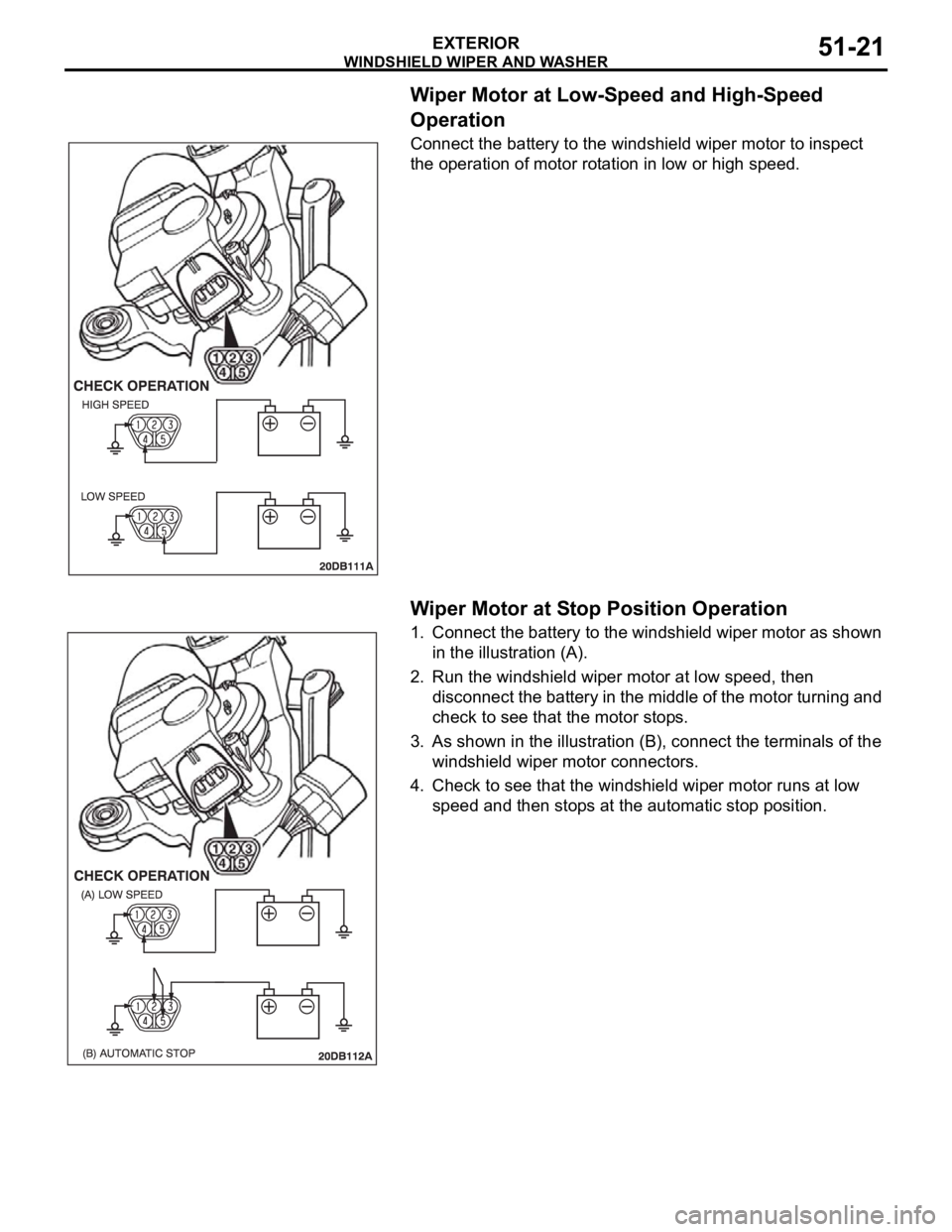
Wiper Motor at Low-Speed and High-Speed
Operation
Connect the battery to the windshield wiper motor to inspect
the operation of motor rotation in low or high speed.
.
Wiper Motor at Stop Position Operation
1. Connect the battery to the windshield wiper motor as shown
in the illustration (A).
2. Run the windshield wiper motor at low speed, then
disconnect the battery in the middle of the motor turning and
check to see that the motor stops.
3. As shown in the illustration (B), connect the terminals of the
windshield wiper motor connectors.
4. Check to see that the windshield wiper motor runs at low
speed and then stops at the automatic stop position.
Page 1057 of 1500
WINDSHIELD WIPER AND WASHER
EXTERIOR51-24
NOTE: For removal and installation of the wiper and
washer switch, refer to GROUP 54A, Column switch
P.54A-170.
INSPECTIONM1511008300147
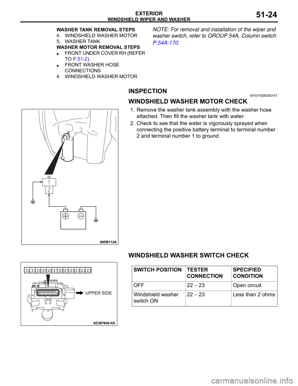
WINDSHIELD WASHER MOTOR CHECK
1. Remove the washer tank assembly with the washer hose
attached. Then fill the washer tank with water.
2. Check to see that the water is vigorously sprayed when
connecting the positive battery terminal to terminal number
2 and terminal number 1 to ground.
WINDSHIELD WASHER SWITCH CHECK
4. WINDSHIELD WASHER MOTOR
5. WASHER TANK
WASHER MOTOR REMOVAL STEPS
FRONT UNDER COVER RH (REFER
TO P.51-2).
FRONT WASHER HOSE
CONNECTIONS
4. WINDSHIELD WASHER MOTOR WASHER TANK REMOVAL STEPS
SWITCH POSITION TESTER
CONNECTIONSPECIFIED
CONDITION
OFF 22
23 Open circuit
Windshield washer
switch ON22
23 Less than 2 ohms