Battery MITSUBISHI 380 2005 Workshop Manual
[x] Cancel search | Manufacturer: MITSUBISHI, Model Year: 2005, Model line: 380, Model: MITSUBISHI 380 2005Pages: 1500, PDF Size: 47.87 MB
Page 1062 of 1500
DOOR MIRROR
EXTERIOR51-29
REMOVAL SERVICE POINT
.
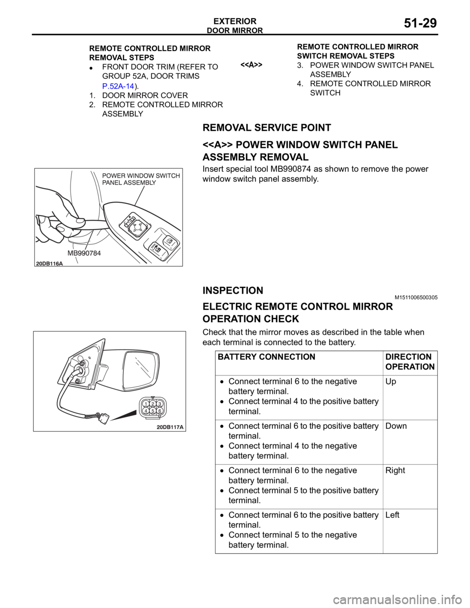
<> POWER WINDOW SWITCH PANEL
ASSEMBLY REMOVAL
Insert special tool MB990874 as shown to remove the power
window switch panel assembly.
INSPECTIONM1511006500305
ELECTRIC REMOTE CONTROL MIRROR
OPERATION CHECK
Check that the mirror moves as described in the table when
each terminal is connected to the battery.
REMOTE CONTROLLED MIRROR
REMOVAL STEPS
FRONT DOOR TRIM (REFER TO
GROUP 52A, DOOR TRIMS
P.52A-14).
1. DOOR MIRROR COVER
2. REMOTE CONTROLLED MIRROR
ASSEMBLYREMOTE CONTROLLED MIRROR
SWITCH REMOVAL STEPS<>3. POWER WINDOW SWITCH PANEL
ASSEMBLY
4. REMOTE CONTROLLED MIRROR
SWITCH
BATTERY CONNECTION DIRECTION
OPERATION
Connect terminal 6 to the negative
battery terminal.
Connect terminal 4 to the positive battery
terminal.Up
Connect terminal 6 to the positive battery
terminal.
Connect terminal 4 to the negative
battery terminal.Down
Connect terminal 6 to the negative
battery terminal.
Connect terminal 5 to the positive battery
terminal.Right
Connect terminal 6 to the positive battery
terminal.
Connect terminal 5 to the negative
battery terminal.Left
Page 1069 of 1500
BODY42-2
DOOR . . . . . . . . . . . . . . . . . . . . . . . . .42-23
GENERAL DESCRIPTION . . . . . .
42-23
CENTRAL DOOR LOCKING SYSTEM
DIAGNOSIS . . . . . . . . . . . . . . . . . . . . . . 42-23
POWER WINDOW DIAGNOSIS . . . . . . 42-23
DOOR DIAGNOSIS . . . . . . . . . . . . . . . . 42-23
INTRODUCTION TO GLASS AND DOOR
DIAGNOSIS . . . . . . . . . . . . . . . . . . . . . . 42-23
GLASS AND DOOR DIAGNOSTIC
TROUBLESHOOTING STRATEGY . . . 42-23
SYMPTOM CHART . . . . . . . . . . . . . . . . 42-24
SYMPTOM PROCEDURES . . . . . . . . . 42-24
HOW TO LOCATE WIND NOISE . . . . . 42-27
SPECIAL TOOLS. . . . . . . . . . . . . .42-28
ON-VEHICLE SERVICE. . . . . . . . .42-30
DOOR FIT ADJUSTMENT. . . . . . . . . . . 42-30
DOOR WINDOW GLASS ADJUSTMENT42-31
GLASS SLIDING MECHANISM CHECK
AND ADJUSTMENT . . . . . . . . . . . . . . . 42-32
POWER WINDOW TIMER FUNCTION
CHECK . . . . . . . . . . . . . . . . . . . . . . . . . 42-32
POWER WINDOW OPERATING
CURRENT CHECK . . . . . . . . . . . . . . . . 42-33
POWER WINDOW RELAY CHECK . . . 42-33
CIRCUIT BREAKER (INCORPORATED IN
THE POWER WINDOW MOTOR)
INSPECTION . . . . . . . . . . . . . . . . . . . . . 42-34
POWER WINDOW CHECK . . . . . . . . . . 42-34
CENTRAL DOOR LOCKING SYSTEM
INSPECTION . . . . . . . . . . . . . . . . . . . . . 42-34
DOOR OUTSIDE HANDLE PLAY CHECK42-35
DOOR INSIDE HANDLE PLAY CHECK 42-35
DOOR ASSEMBLY . . . . . . . . . . . .42-37
REMOVAL AND INSTALLATION . . . . . 42-37
INSPECTION . . . . . . . . . . . . . . . . . . . . . 42-38
DOOR GLASS AND REGULATOR42-39
REMOVAL AND INSTALLATION . . . . . 42-39
INSPECTION . . . . . . . . . . . . . . . . . . . . . 42-43
DOOR HANDLE AND LATCH . . . .42-46
REMOVAL AND INSTALLATION . . . . . 42-46
INSPECTION . . . . . . . . . . . . . . . . . . . . . 42-49
WINDOW GLASS RUNCHANNEL
AND DOOR OPENING
WEATHERSTRIP . . . . . . . . . . . . . .
42-52
REMOVAL AND INSTALLATION . . . . . . 42-52
TRUNK LID. . . . . . . . . . . . . . . . 42-60
TRUNK LID DIAGNOSIS . . . . . . . .
42-60
INTRODUCTION TO TRUNK LID
DIAGNOSIS . . . . . . . . . . . . . . . . . . . . . . 42-60
TRUNK LID DIAGNOSTIC
TROUBLESHOOTING STRATEGY . . . . 42-60
SYMPTOM CHART . . . . . . . . . . . . . . . . 42-60
SYMPTOM PROCEDURES . . . . . . . . . . 42-60
ON-VEHICLE SERVICE . . . . . . . . .42-61
ADJUSTMENT OF CLEARANCE
AROUND TRUNK LID . . . . . . . . . . . . . . 42-61
TRUNK LID LATCH ADJUSTMENT. . . . 42-61
TRUNK LID HEIGHT ADJUSTMENT . . . 42-62
TRUNK LID . . . . . . . . . . . . . . . . . . .42-63
REMOVAL AND INSTALLATION . . . . . . 42-63
INSPECTION . . . . . . . . . . . . . . . . . . . . . 42-65
KEYLESS ENTRY SYSTEM 42-67
GENERAL DESCRIPTION . . . . . . .
42-67
KEYLESS ENTRY SYSTEM
DIAGNOSIS . . . . . . . . . . . . . . . . . .
42-68
SPECIAL TOOL . . . . . . . . . . . . . . .42-68
ON-VEHICLE SERVICE . . . . . . . . .42-69
TRANSMITTER BATTERY CHECK . . . . 42-69
HOW TO REPLACE THE TRANSMITTER
BATTERY . . . . . . . . . . . . . . . . . . . . . . . . 42-70
KEYLESS ENTRY SYSTEM INSPECTION42-71
KEYLESS ENTRY SYSTEM TIMER LOCK
FUNCTION INSPECTION . . . . . . . . . . . 42-71
ENABLING/DISABLING THE
ANSWERBACK FUNCTION . . . . . . . . . 42-72
HOW TO REGISTER SECRET CODE . 42-73
Continued on next page
Page 1100 of 1500
DOOR
BODY42-33
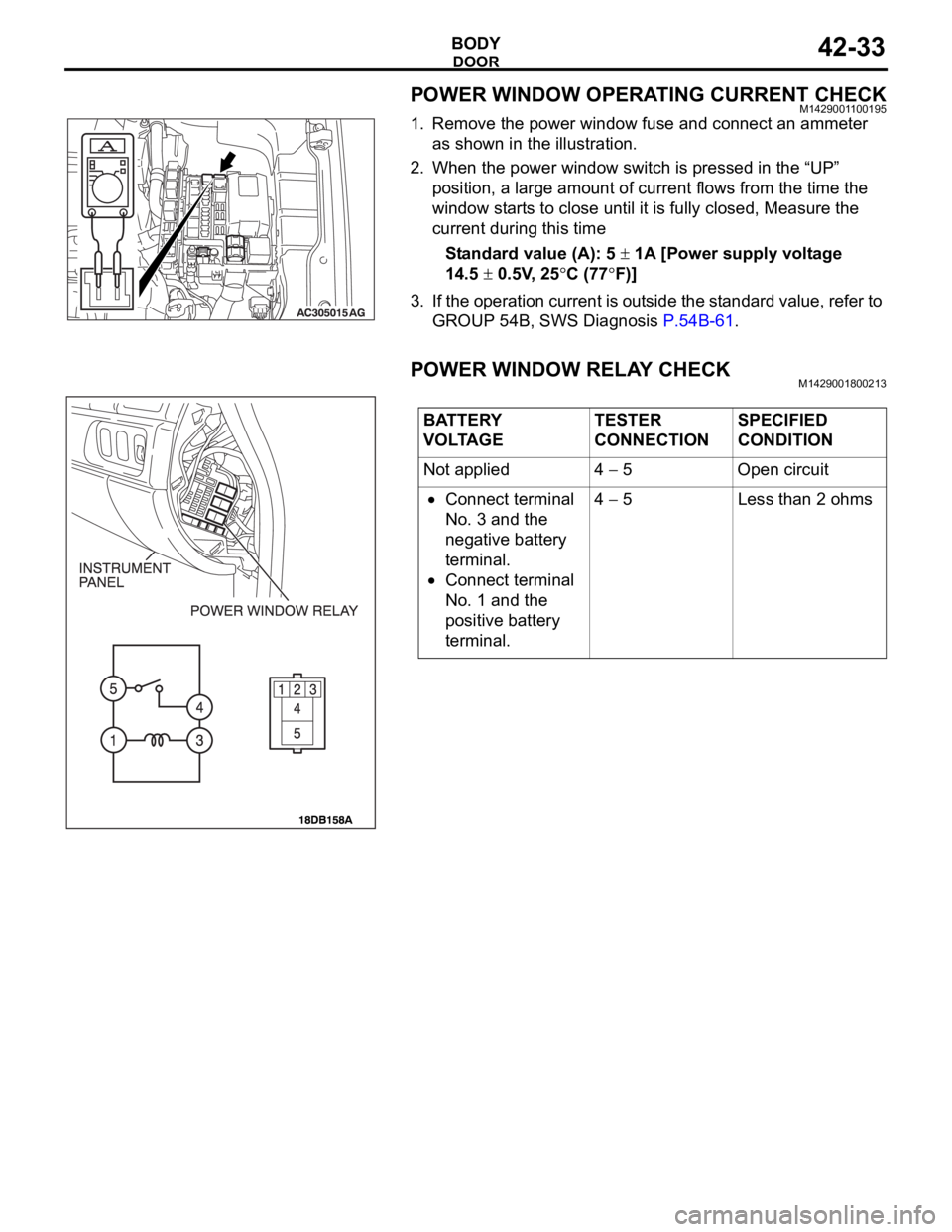
POWER WINDOW OPERATING CURRENT CHECKM1429001100195
1. Remove the power window fuse and connect an ammeter
as shown in the illustration.
2. When the power window switch is pressed in the “UP”
position, a large amount of current flows from the time the
window starts to close until it is fully closed, Measure the
current during this time
Standard value (A): 5
1A [Power supply voltage
14.5
0.5V, 25C (77F)]
3. If the operation current is outside the standard value, refer to
GROUP 54B, SWS Diagnosis P.54B-61.
POWER WINDOW RELAY CHECKM1429001800213
BATTERY
VOLTAGETESTER
CONNECTIONSPECIFIED
CONDITION
Not applied 4
5 Open circuit
Connect terminal
No. 3 and the
negative battery
terminal.
Connect terminal
No. 1 and the
positive battery
terminal.4
5 Less than 2 ohms
Page 1110 of 1500
DOOR
BODY42-43
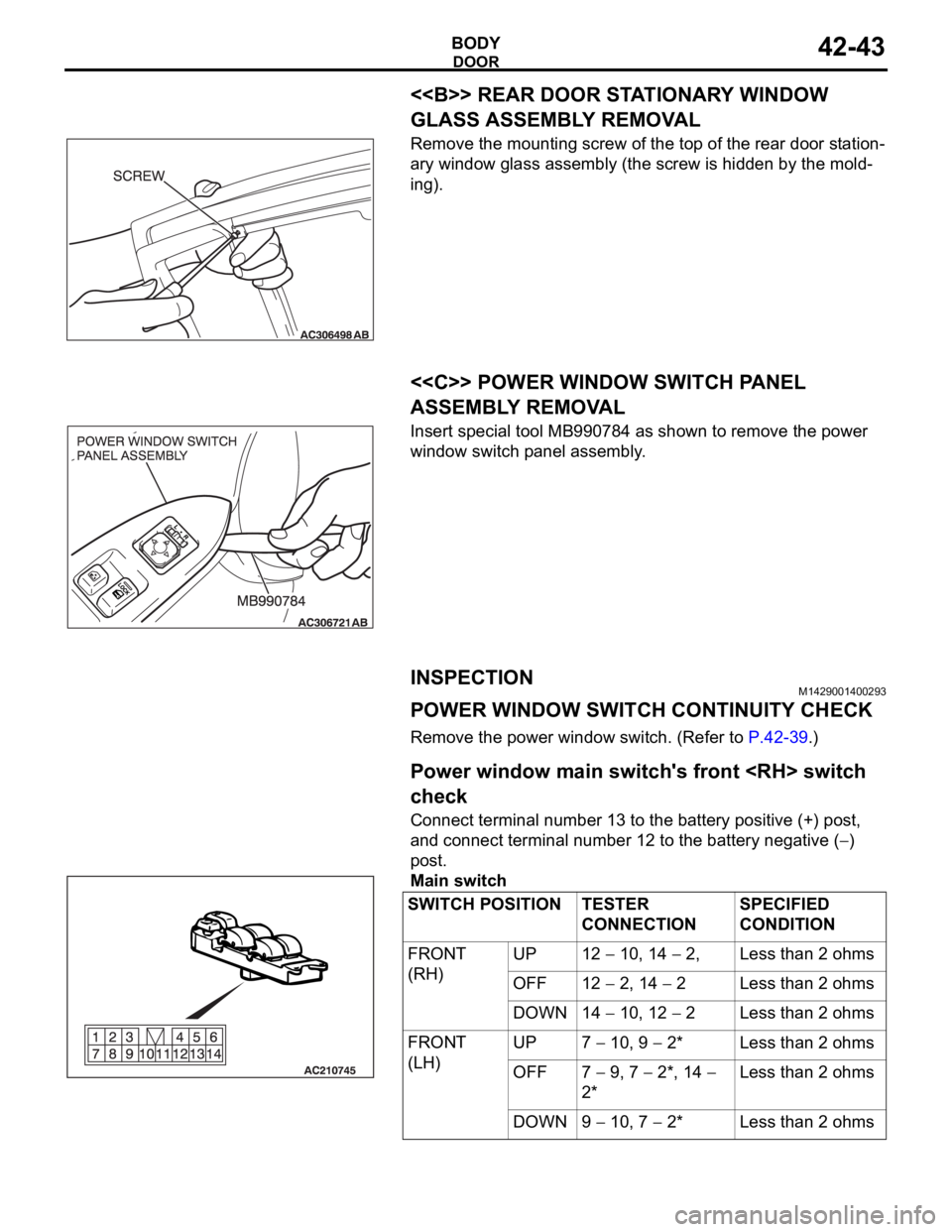
<> REAR DOOR STATIONARY WINDOW
GLASS ASSEMBLY REMOVAL
Remove the mounting screw of the top of the rear door station-
ary window glass assembly (the screw is hidden by the mold-
ing).
.
<
ASSEMBLY REMOVAL
Insert special tool MB990784 as shown to remove the power
window switch panel assembly.
INSPECTIONM1429001400293
POWER WINDOW SWITCH CONTINUITY CHECK
Remove the power window switch. (Refer to P.42-39.).
Power window main switch's front
check
Connect terminal number 13 to the battery positive (+) post,
and connect terminal number 12 to the battery negative (
)
post.
Main switch
SWITCH POSITION TESTER
CONNECTIONSPECIFIED
CONDITION
FRONT
(RH)UP 12
10, 14 2, Less than 2 ohms
OFF 12
2, 14 2 Less than 2 ohms
DOWN 14
10, 12 2 Less than 2 ohms
FRONT
(LH)UP 7
10, 9 2* Less than 2 ohms
OFF 7
9, 7 2*, 14
2*Less than 2 ohms
DOWN 9
10, 7 2* Less than 2 ohms
Page 1112 of 1500
DOOR
BODY42-45
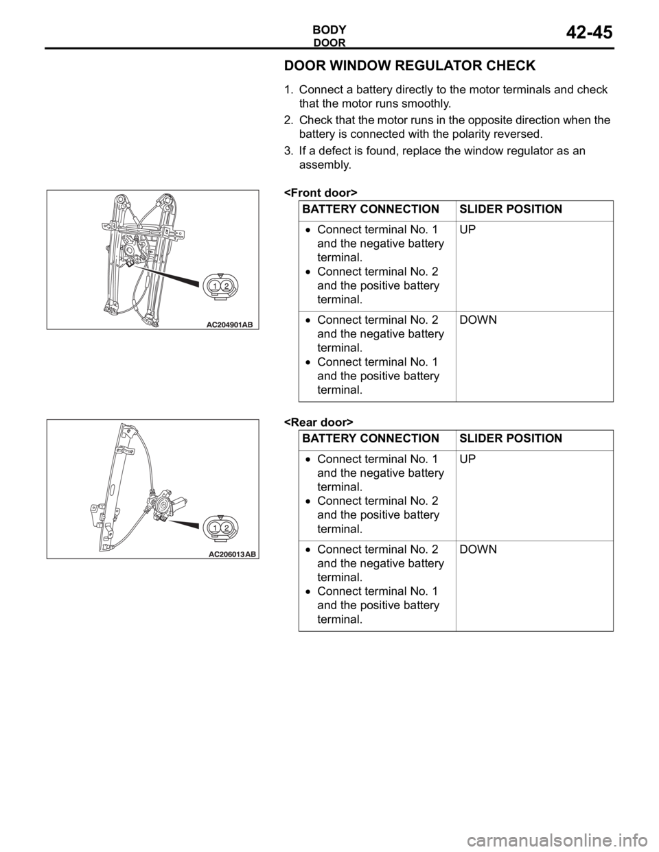
DOOR WINDOW REGULATOR CHECK
.
1. Connect a battery directly to the motor terminals and check
that the motor runs smoothly.
2. Check that the motor runs in the opposite direction when the
battery is connected with the polarity reversed.
3. If a defect is found, replace the window regulator as an
assembly.
.
.
Connect terminal No. 1
and the negative battery
terminal.
Connect terminal No. 2
and the positive battery
terminal.UP
Connect terminal No. 2
and the negative battery
terminal.
Connect terminal No. 1
and the positive battery
terminal.DOWN
BATTERY CONNECTION SLIDER POSITION
Connect terminal No. 1
and the negative battery
terminal.
Connect terminal No. 2
and the positive battery
terminal.UP
Connect terminal No. 2
and the negative battery
terminal.
Connect terminal No. 1
and the positive battery
terminal.DOWN
Page 1116 of 1500
DOOR
BODY42-49
INSPECTIONM1423004700411
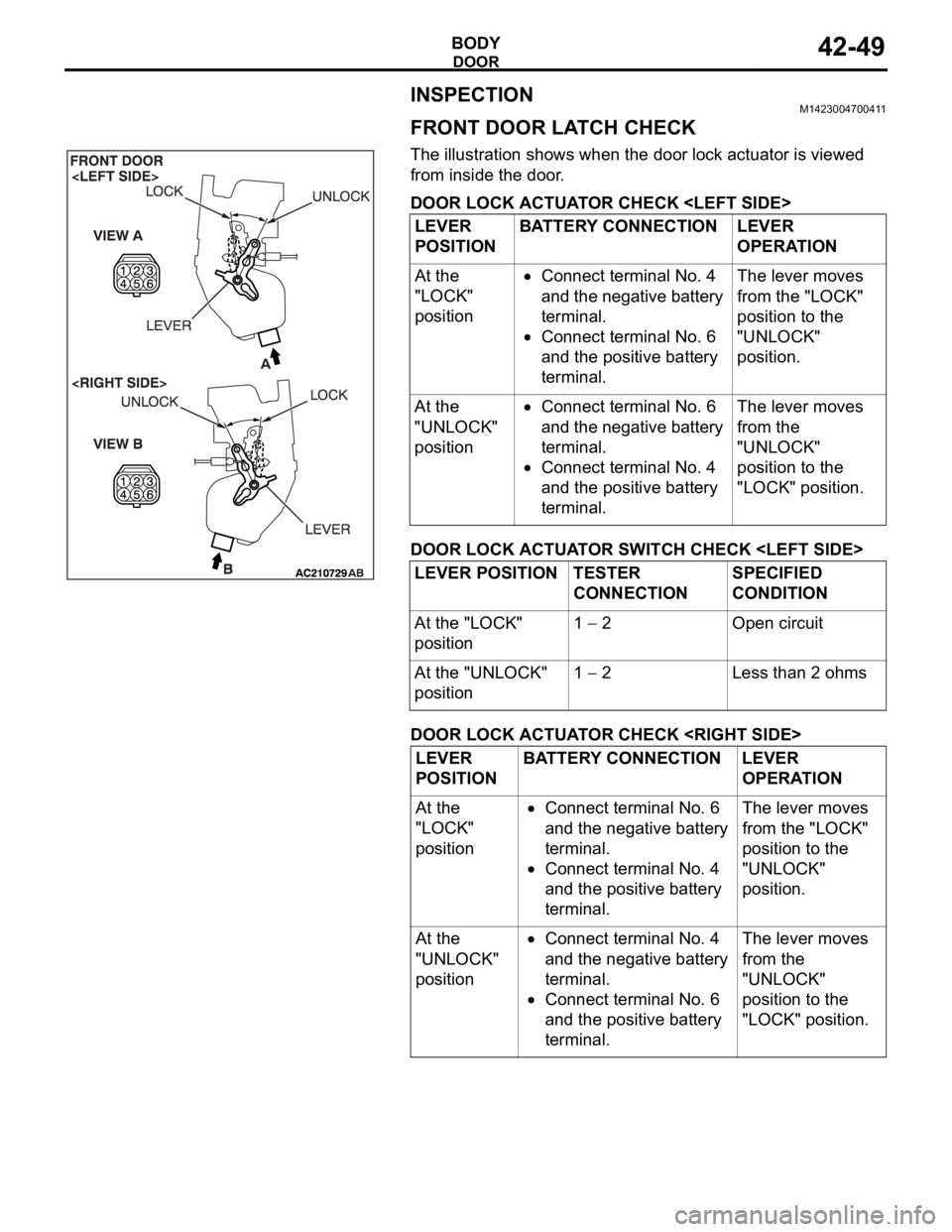
FRONT DOOR LATCH CHECK
The illustration shows when the door lock actuator is viewed
from inside the door.
DOOR LOCK ACTUATOR CHECK
DOOR LOCK ACTUATOR SWITCH CHECK
DOOR LOCK ACTUATOR CHECK
POSITIONBATTERY CONNECTION LEVER
OPERATION
At the
"LOCK"
position
Connect terminal No. 4
and the negative battery
terminal.
Connect terminal No. 6
and the positive battery
terminal.The lever moves
from the "LOCK"
position to the
"UNLOCK"
position.
At the
"UNLOCK"
position
Connect terminal No. 6
and the negative battery
terminal.
Connect terminal No. 4
and the positive battery
terminal.The lever moves
from the
"UNLOCK"
position to the
"LOCK" position.
LEVER POSITION TESTER
CONNECTIONSPECIFIED
CONDITION
At the "LOCK"
position1
2 Open circuit
At the "UNLOCK"
position1
2 Less than 2 ohms
LEVER
POSITIONBATTERY CONNECTION LEVER
OPERATION
At the
"LOCK"
position
Connect terminal No. 6
and the negative battery
terminal.
Connect terminal No. 4
and the positive battery
terminal.The lever moves
from the "LOCK"
position to the
"UNLOCK"
position.
At the
"UNLOCK"
position
Connect terminal No. 4
and the negative battery
terminal.
Connect terminal No. 6
and the positive battery
terminal.The lever moves
from the
"UNLOCK"
position to the
"LOCK" position.
Page 1117 of 1500
DOOR
BODY42-50
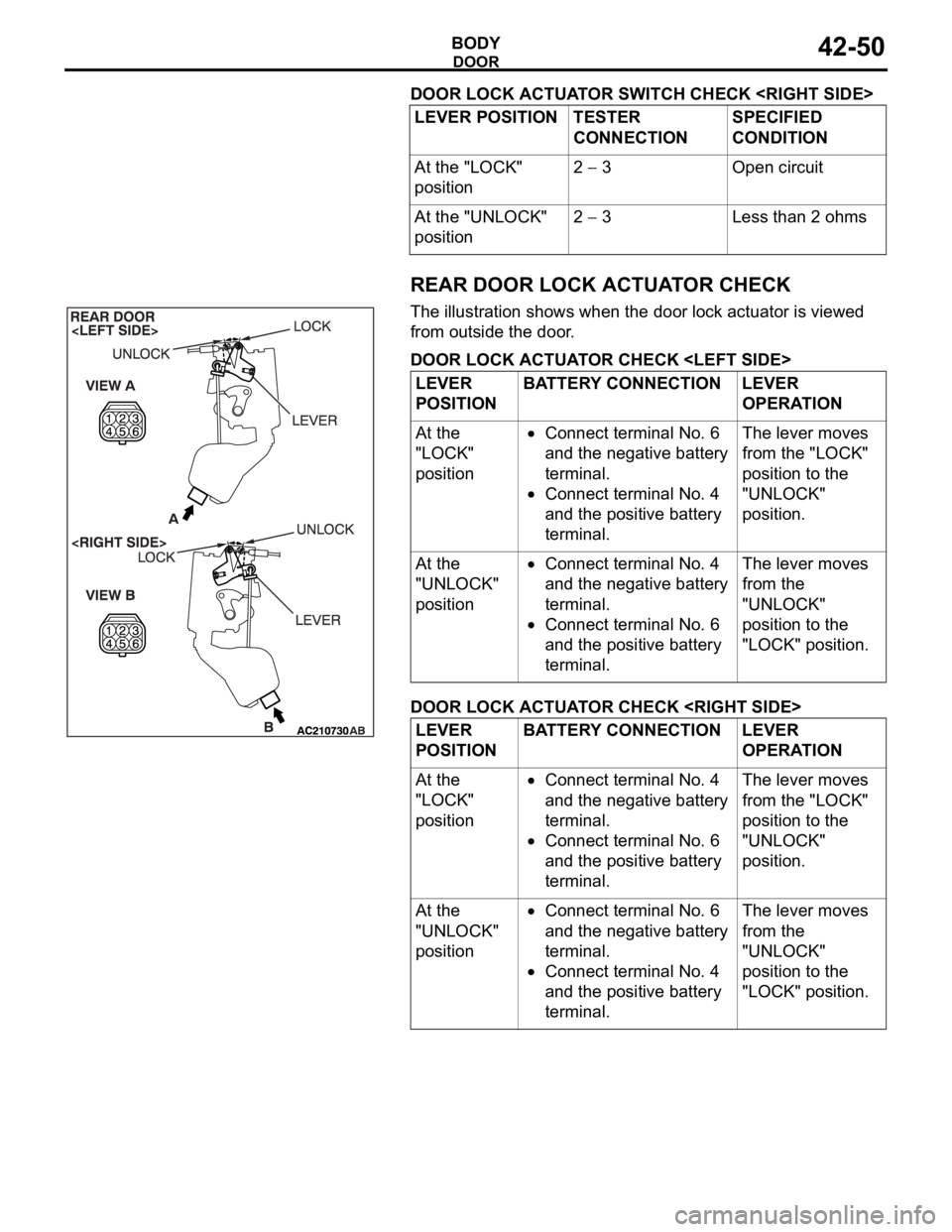
DOOR LOCK ACTUATOR SWITCH CHECK
REAR DOOR LOCK ACTUATOR CHECK
The illustration shows when the door lock actuator is viewed
from outside the door.
DOOR LOCK ACTUATOR CHECK
DOOR LOCK ACTUATOR CHECK
CONNECTIONSPECIFIED
CONDITION
At the "LOCK"
position2
3 Open circuit
At the "UNLOCK"
position2
3 Less than 2 ohms
LEVER
POSITIONBATTERY CONNECTION LEVER
OPERATION
At the
"LOCK"
position
Connect terminal No. 6
and the negative battery
terminal.
Connect terminal No. 4
and the positive battery
terminal.The lever moves
from the "LOCK"
position to the
"UNLOCK"
position.
At the
"UNLOCK"
position
Connect terminal No. 4
and the negative battery
terminal.
Connect terminal No. 6
and the positive battery
terminal.The lever moves
from the
"UNLOCK"
position to the
"LOCK" position.
LEVER
POSITIONBATTERY CONNECTION LEVER
OPERATION
At the
"LOCK"
position
Connect terminal No. 4
and the negative battery
terminal.
Connect terminal No. 6
and the positive battery
terminal.The lever moves
from the "LOCK"
position to the
"UNLOCK"
position.
At the
"UNLOCK"
position
Connect terminal No. 6
and the negative battery
terminal.
Connect terminal No. 4
and the positive battery
terminal.The lever moves
from the
"UNLOCK"
position to the
"LOCK" position.
Page 1118 of 1500
DOOR
BODY42-51
FUEL LID D00R ACTUATOR CHECK
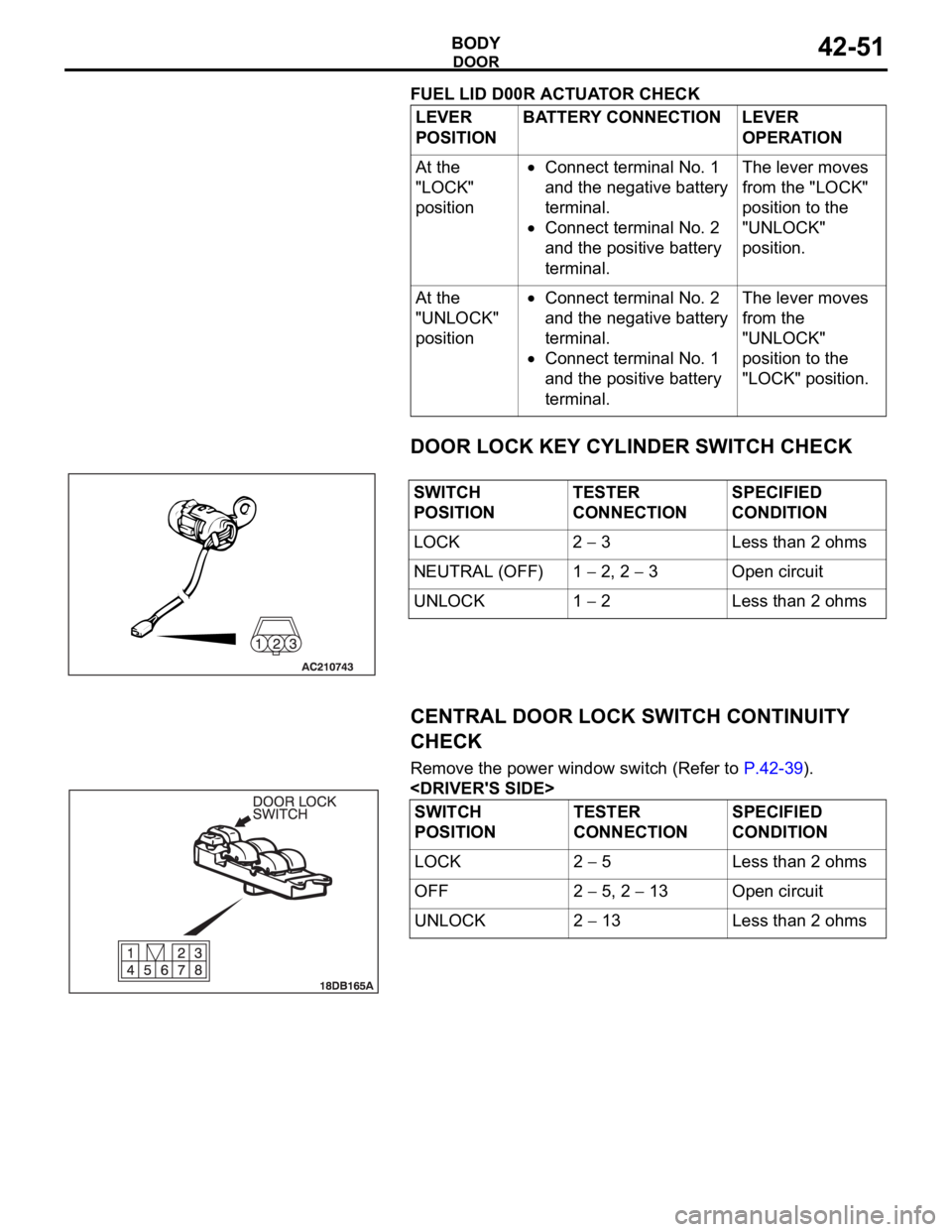
DOOR LOCK KEY CYLINDER SWITCH CHECK
CENTRAL DOOR LOCK SWITCH CONTINUITY
CHECK
Remove the power window switch (Refer to P.42-39).
POSITIONBATTERY CONNECTION LEVER
OPERATION
At the
"LOCK"
position
Connect terminal No. 1
and the negative battery
terminal.
Connect terminal No. 2
and the positive battery
terminal.The lever moves
from the "LOCK"
position to the
"UNLOCK"
position.
At the
"UNLOCK"
position
Connect terminal No. 2
and the negative battery
terminal.
Connect terminal No. 1
and the positive battery
terminal.The lever moves
from the
"UNLOCK"
position to the
"LOCK" position.
SWITCH
POSITIONTESTER
CONNECTIONSPECIFIED
CONDITION
LOCK 2
3 Less than 2 ohms
NEUTRAL (OFF) 1
2, 2 3 Open circuit
UNLOCK 1
2 Less than 2 ohms
SWITCH
POSITIONTESTER
CONNECTIONSPECIFIED
CONDITION
LOCK 2
5 Less than 2 ohms
OFF 2
5, 2 13 Open circuit
UNLOCK 2
13 Less than 2 ohms
Page 1132 of 1500
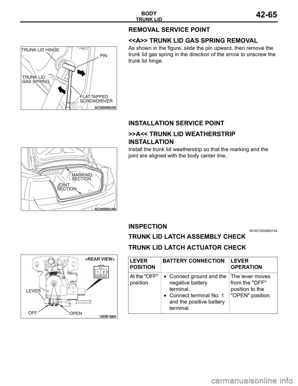
Page 1136 of 1500
KEYLESS ENTRY SYSTEM
BODY42-69
ON-VEHICLE SERVICE
INSPECTIONM1428003800089
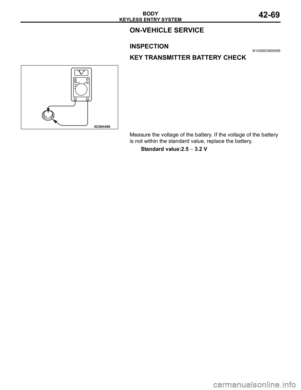
KEY TRANSMITTER BATTERY CHECK
Measure the voltage of the battery. If the voltage of the battery
is not within the standard value, replace the battery.
Standard value:2.5
3.2 V