Battery MITSUBISHI 380 2005 Workshop Manual
[x] Cancel search | Manufacturer: MITSUBISHI, Model Year: 2005, Model line: 380, Model: MITSUBISHI 380 2005Pages: 1500, PDF Size: 47.87 MB
Page 1349 of 1500
AUTO-CRUISE CONTROL
ENGINE AND EMISSION CONTROL17-18
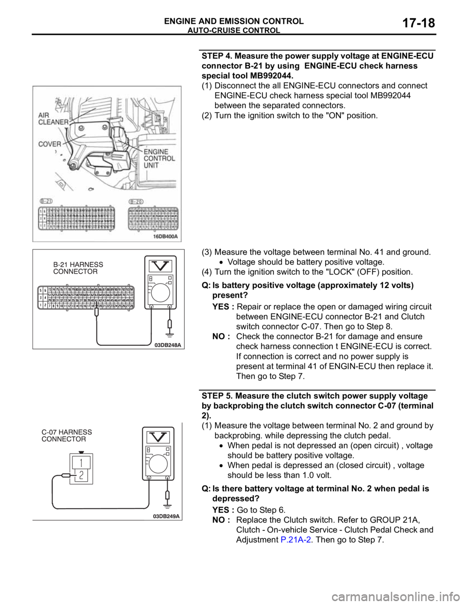
STEP 4. Measure the power supply voltage at ENGINE-ECU
connector B-21 by using ENGINE-ECU check harness
special tool MB992044.
(1) Disconnect the all ENGINE-ECU connectors and connect
ENGINE-ECU check harness special tool MB992044
between the separated connectors.
(2) Turn the ignition switch to the "ON" position.
(3) Measure the voltage between terminal No. 41 and ground.
Voltage should be battery positive voltage.
(4) Turn the ignition switch to the "LOCK" (OFF) position.
Q: Is battery positive voltage (approximately 12 volts)
present?
YES : Repair or replace the open or damaged wiring circuit
between ENGINE-ECU connector B-21 and Clutch
switch connector C-07. Then go to Step 8.
NO : Check the connector B-21 for damage and ensure
check harness connection t ENGINE-ECU is correct.
If connection is correct and no power supply is
present at terminal 41 of ENGIN-ECU then replace it.
Then go to Step 7.
STEP 5. Measure the clutch switch power supply voltage
by backprobing the clutch switch connector C-07 (terminal
2).
(1) Measure the voltage between terminal No. 2 and ground by
backprobing. while depressing the clutch pedal.
When pedal is not depressed an (open circuit) , voltage
should be battery positive voltage.
When pedal is depressed an (closed circuit) , voltage
should be less than 1.0 volt.
Q: Is there battery voltage at terminal No. 2 when pedal is
depressed?
YES : Go to Step 6.
NO : Replace the Clutch switch. Refer to GROUP 21A,
Clutch - On-vehicle Service - Clutch Pedal Check and
Adjustment P.21A-2. Then go to Step 7.
Page 1354 of 1500
AUTO-CRUISE CONTROL
ENGINE AND EMISSION CONTROL17-23
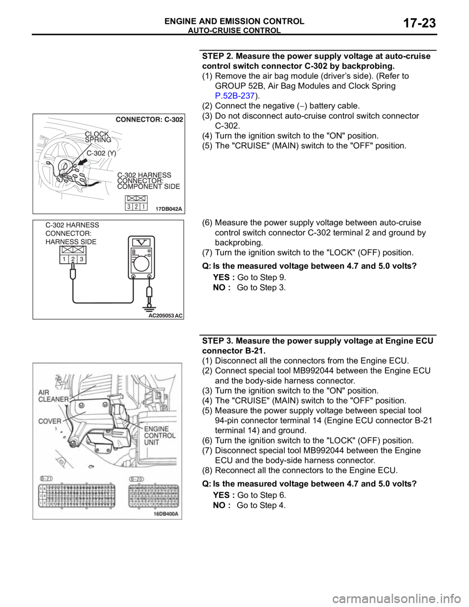
STEP 2. Measure the power supply voltage at auto-cruise
control switch connector C-302 by backprobing.
(1) Remove the air bag module (driver’s side). (Refer to
GROUP 52B, Air Bag Modules and Clock Spring
P.52B-237).
(2) Connect the negative (
) battery cable.
(3) Do not disconnect auto-cruise control switch connector
C-302.
(4) Turn the ignition switch to the "ON" position.
(5) The "CRUISE" (MAIN) switch to the "OFF" position.
(6) Measure the power supply voltage between auto-cruise
control switch connector C-302 terminal 2 and ground by
backprobing.
(7) Turn the ignition switch to the "LOCK" (OFF) position.
Q: Is the measured voltage between 4.7 and 5.0 volts?
YES : Go to Step 9.
NO : Go to Step 3.
STEP 3. Measure the power supply voltage at Engine ECU
connector B-21.
(1) Disconnect all the connectors from the Engine ECU.
(2) Connect special tool MB992044 between the Engine ECU
and the body-side harness connector.
(3) Turn the ignition switch to the "ON" position.
(4) The "CRUISE" (MAIN) switch to the "OFF" position.
(5) Measure the power supply voltage between special tool
94-pin connector terminal 14 (Engine ECU connector B-21
terminal 14) and ground.
(6) Turn the ignition switch to the "LOCK" (OFF) position.
(7) Disconnect special tool MB992044 between the Engine
ECU and the body-side harness connector.
(8) Reconnect all the connectors to the Engine ECU.
Q: Is the measured voltage between 4.7 and 5.0 volts?
YES : Go to Step 6.
NO : Go to Step 4.
Page 1366 of 1500
AUTO-CRUISE CONTROL
ENGINE AND EMISSION CONTROL17-35
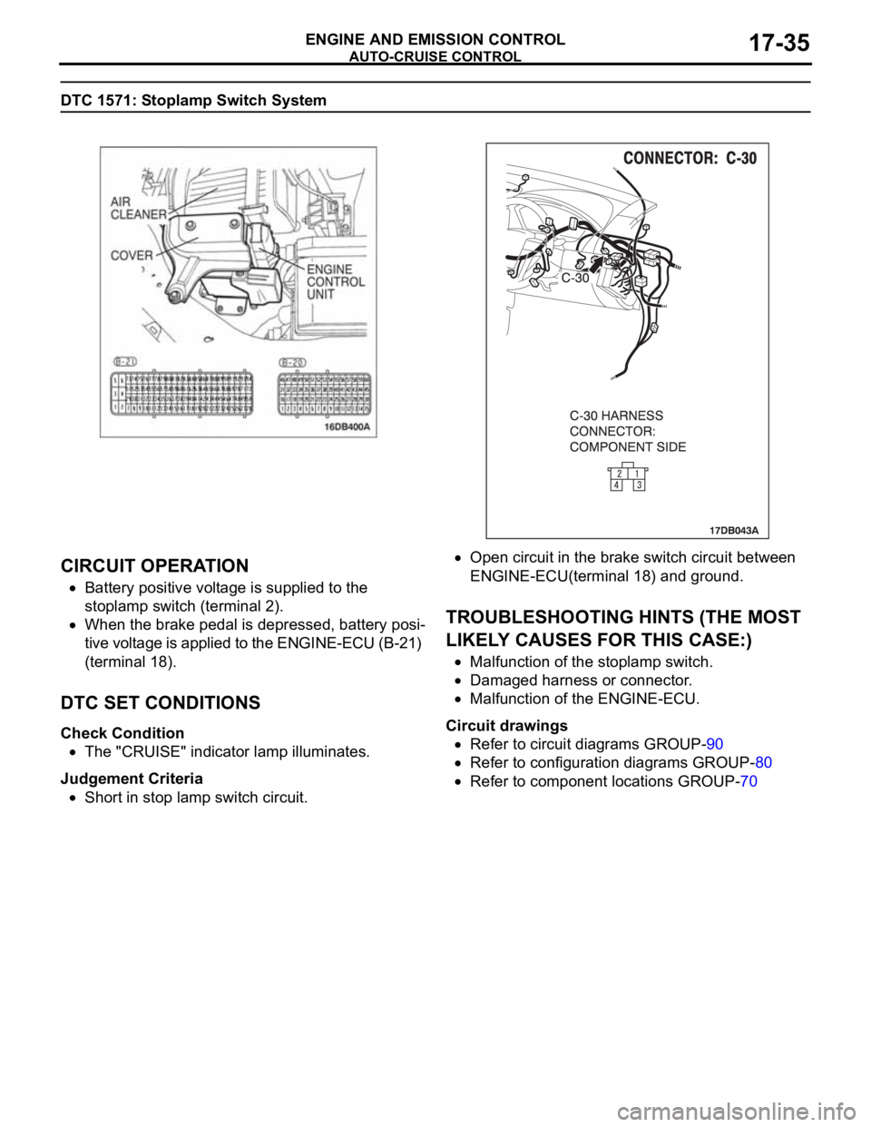
DTC 1571: Stoplamp Switch System
.
CIRCUIT OPERATION
Battery positive voltage is supplied to the
stoplamp switch (terminal 2).
When the brake pedal is depressed, battery posi-
tive voltage is applied to the ENGINE-ECU (B-21)
(terminal 18).
.
DTC SET CONDITIONS
Check Condition
The "CRUISE" indicator lamp illuminates.
Judgement Criteria
Short in stop lamp switch circuit.
Open circuit in the brake switch circuit between
ENGINE-ECU(terminal 18) and ground.
.
TROUBLESHOOTING HINTS (THE MOST
LIKELY CAUSES FOR THIS CASE:)
Malfunction of the stoplamp switch.
Damaged harness or connector.
Malfunction of the ENGINE-ECU.
Circuit drawings
Refer to circuit diagrams GROUP-90
Refer to configuration diagrams GROUP-80
Refer to component locations GROUP-70
Page 1368 of 1500
AUTO-CRUISE CONTROL
ENGINE AND EMISSION CONTROL17-37
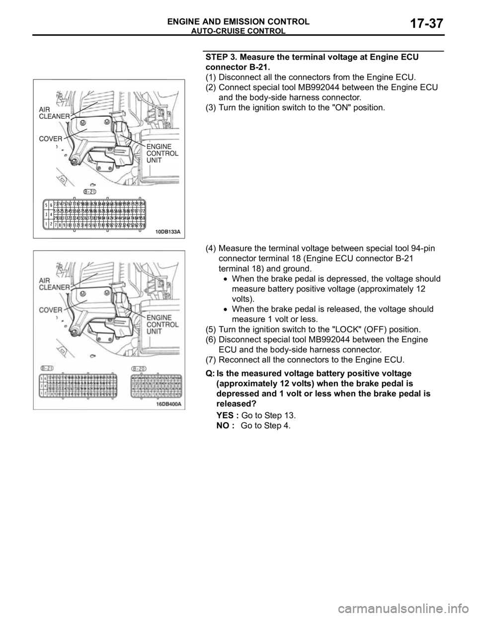
STEP 3. Measure the terminal voltage at Engine ECU
connector B-21.
(1) Disconnect all the connectors from the Engine ECU.
(2) Connect special tool MB992044 between the Engine ECU
and the body-side harness connector.
(3) Turn the ignition switch to the "ON" position.
(4) Measure the terminal voltage between special tool 94-pin
connector terminal 18 (Engine ECU connector B-21
terminal 18) and ground.
When the brake pedal is depressed, the voltage should
measure battery positive voltage (approximately 12
volts).
When the brake pedal is released, the voltage should
measure 1 volt or less.
(5) Turn the ignition switch to the "LOCK" (OFF) position.
(6) Disconnect special tool MB992044 between the Engine
ECU and the body-side harness connector.
(7) Reconnect all the connectors to the Engine ECU.
Q: Is the measured voltage battery positive voltage
(approximately 12 volts) when the brake pedal is
depressed and 1 volt or less when the brake pedal is
released?
YES : Go to Step 13.
NO : Go to Step 4.
Page 1371 of 1500
AUTO-CRUISE CONTROL
ENGINE AND EMISSION CONTROL17-40
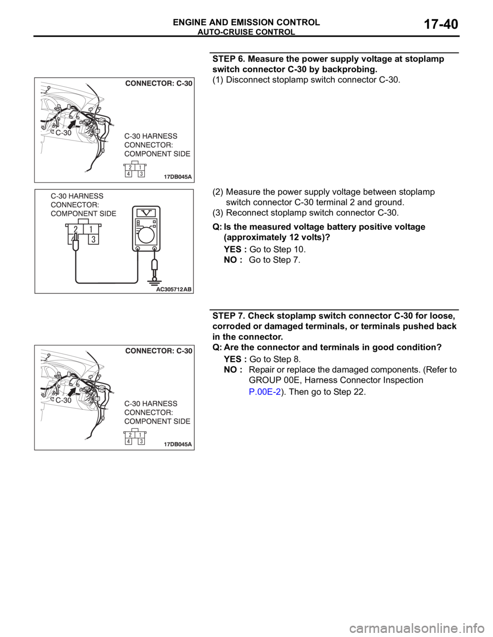
STEP 6. Measure the power supply voltage at stoplamp
switch connector C-30 by backprobing.
(1) Disconnect stoplamp switch connector C-30.
(2) Measure the power supply voltage between stoplamp
switch connector C-30 terminal 2 and ground.
(3) Reconnect stoplamp switch connector C-30.
Q: Is the measured voltage battery positive voltage
(approximately 12 volts)?
YES : Go to Step 10.
NO : Go to Step 7.
STEP 7. Check stoplamp switch connector C-30 for loose,
corroded or damaged terminals, or terminals pushed back
in the connector.
Q: Are the connector and terminals in good condition?
YES : Go to Step 8.
NO : Repair or replace the damaged components. (Refer to
GROUP 00E, Harness Connector Inspection
P.00E-2). Then go to Step 22.
Page 1376 of 1500
AUTO-CRUISE CONTROL
ENGINE AND EMISSION CONTROL17-45
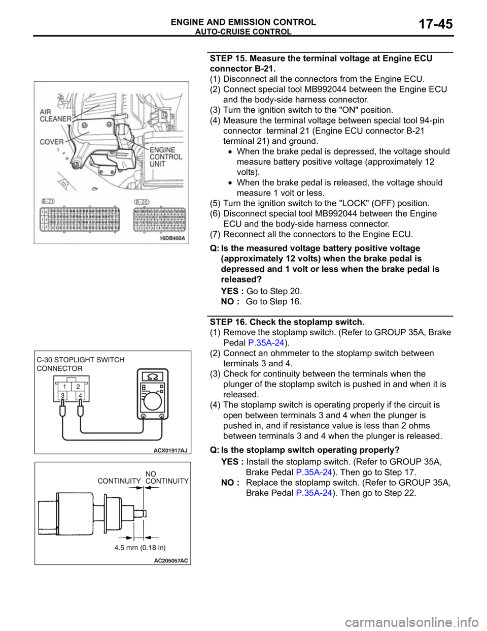
STEP 15. Measure the terminal voltage at Engine ECU
connector B-21.
(1) Disconnect all the connectors from the Engine ECU.
(2) Connect special tool MB992044 between the Engine ECU
and the body-side harness connector.
(3) Turn the ignition switch to the "ON" position.
(4) Measure the terminal voltage between special tool 94-pin
connector terminal 21 (Engine ECU connector B-21
terminal 21) and ground.
When the brake pedal is depressed, the voltage should
measure battery positive voltage (approximately 12
volts).
When the brake pedal is released, the voltage should
measure 1 volt or less.
(5) Turn the ignition switch to the "LOCK" (OFF) position.
(6) Disconnect special tool MB992044 between the Engine
ECU and the body-side harness connector.
(7) Reconnect all the connectors to the Engine ECU.
Q: Is the measured voltage battery positive voltage
(approximately 12 volts) when the brake pedal is
depressed and 1 volt or less when the brake pedal is
released?
YES : Go to Step 20.
NO : Go to Step 16.
STEP 16. Check the stoplamp switch.
(1) Remove the stoplamp switch. (Refer to GROUP 35A, Brake
Pedal P.35A-24).
(2) Connect an ohmmeter to the stoplamp switch between
terminals 3 and 4.
(3) Check for continuity between the terminals when the
plunger of the stoplamp switch is pushed in and when it is
released.
(4) The stoplamp switch is operating properly if the circuit is
open between terminals 3 and 4 when the plunger is
pushed in, and if resistance value is less than 2 ohms
between terminals 3 and 4 when the plunger is released.
Q: Is the stoplamp switch operating properly?
YES : Install the stoplamp switch. (Refer to GROUP 35A,
Brake Pedal P.35A-24). Then go to Step 17.
NO : Replace the stoplamp switch. (Refer to GROUP 35A,
Brake Pedal P.35A-24). Then go to Step 22.
Page 1398 of 1500
AUTO-CRUISE CONTROL
ENGINE AND EMISSION CONTROL17-67
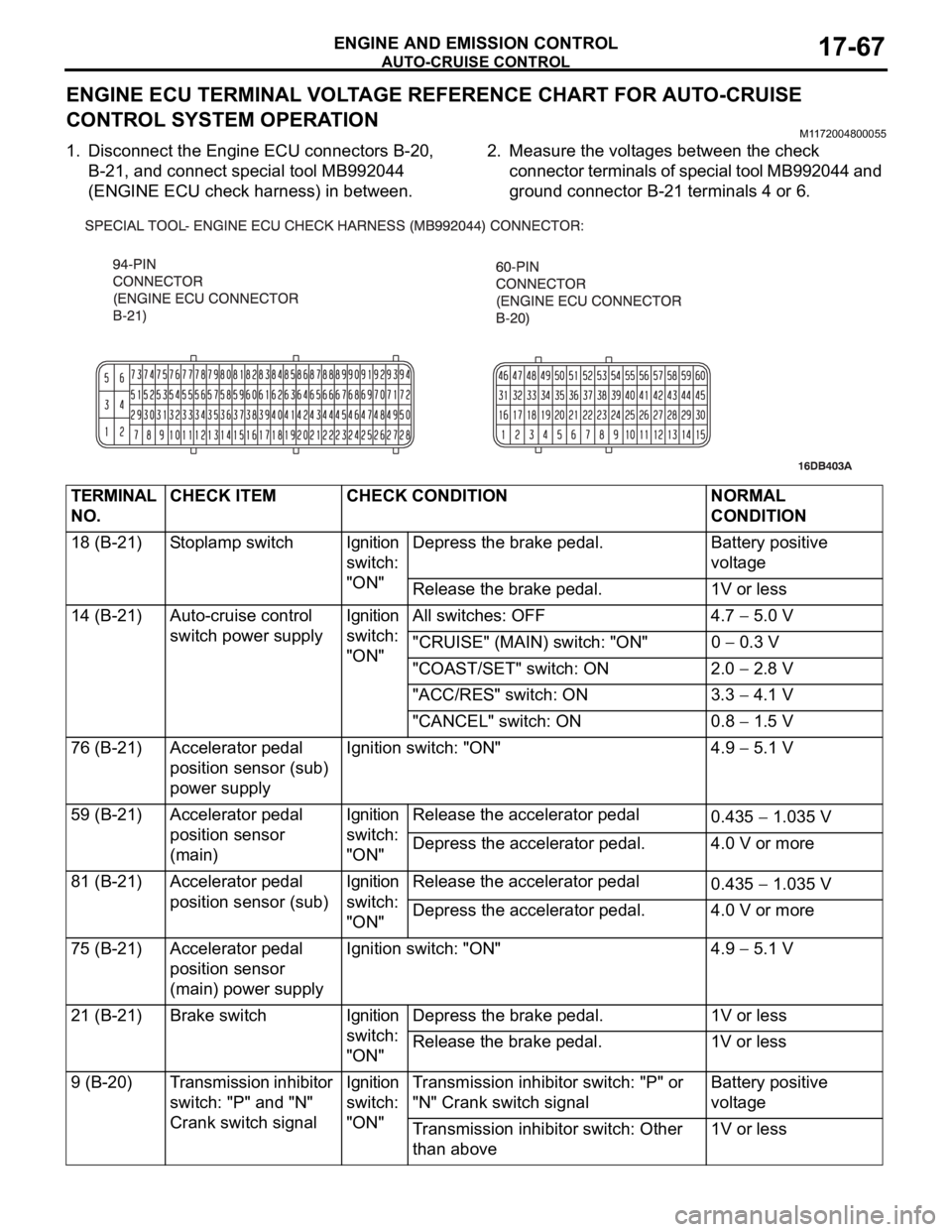
ENGINE ECU TERMINAL VOLTAGE REFERENCE CHART FOR AUTO-CRUISE
CONTROL SYSTEM OPERATION
M1172004800055
1. Disconnect the Engine ECU connectors B-20,
B-21, and connect special tool MB992044
(ENGINE ECU check harness) in between.2. Measure the voltages between the check
connector terminals of special tool MB992044 and
ground connector B-21 terminals 4 or 6.
TERMINAL
NO.CHECK ITEM CHECK CONDITION NORMAL
CONDITION
18 (B-21) Stoplamp switch Ignition
switch:
"ON"Depress the brake pedal. Battery positive
voltage
Release the brake pedal. 1V or less
14 (B-21) Auto-cruise control
switch power supplyIgnition
switch:
"ON"All switches: OFF 4.7
5.0 V
"CRUISE" (MAIN) switch: "ON" 0
0.3 V
"COAST/SET" switch: ON 2.0
2.8 V
"ACC/RES" switch: ON 3.3
4.1 V
"CANCEL" switch: ON 0.8
1.5 V
76 (B-21) Accelerator pedal
position sensor (sub)
power supplyIgnition switch: "ON" 4.9
5.1 V
59 (B-21) Accelerator pedal
position sensor
(main)Ignition
switch:
"ON"Release the accelerator pedal
0.435
1.035 V
Depress the accelerator pedal. 4.0 V or more
81 (B-21) Accelerator pedal
position sensor (sub)Ignition
switch:
"ON"Release the accelerator pedal
0.435
1.035 V
Depress the accelerator pedal. 4.0 V or more
75 (B-21) Accelerator pedal
position sensor
(main) power supplyIgnition switch: "ON" 4.9
5.1 V
21 (B-21) Brake switch Ignition
switch:
"ON"Depress the brake pedal. 1V or less
Release the brake pedal. 1V or less
9 (B-20) Transmission inhibitor
switch: "P" and "N"
Crank switch signalIgnition
switch:
"ON"Transmission inhibitor switch: "P" or
"N" Crank switch signalBattery positive
voltage
Transmission inhibitor switch: Other
than above1V or less
Page 1399 of 1500

AUTO-CRUISE CONTROL
ENGINE AND EMISSION CONTROL17-68
If the air intake duct is removed from the throttle body take great care to keep fingers away
from the throttle plate. The drive motor has very high torque and is capable of random move-
ment at any time. Do not under any circumstances activate the throttle plate by hand.
When removing the throttle body from the intake manifold disconnect the wiring first. During
replacement connect the wiring last.
Do not activate the throttle body using a DC suppy to test the motor,as permanent damage to
the throttle body will result.
10 (B-20) Throttle position
sensor power supplyIgnition switch: "ON" 4.9 5.1 V
57 (B-20) Throttle position
sensor (sub)(1) Accelerator pedal:
Released
(2) Accelerator pedal:
Depressed(1) Throttle
valve fully
closed1035
1250 mV
(2) Throttle
valve fully open4000 mV or more
42 (B-20) Throttle position
sensor (main)(1) Accelerator pedal:
Released
(2) Accelerator pedal:
Depressed(1) Throttle
valve fully
closed1035
1250 mV
(2) Throttle
valve fully open4000 mV or more
49 (B-20) Throttle actuator
control motor (
)
Ignition switch: "ON"
Accelerator pedal: fully closed to fully
openedDecreases slightly
(approx. 2 V) from
battery voltage.
50 (B-20) Throttle actuator
control motor (+)
Ignition switch: "ON"
Accelerator pedal: fully opened to fully
closedDecreases slightly
(approx. 2 V) from
battery voltage. TERMINAL
NO.CHECK ITEM CHECK CONDITION NORMAL
CONDITION
Page 1414 of 1500
EMISSION CONTROL
ENGINE AND EMISSION CONTROL17-83
Required Special Tool:
MB995061: Purge Flow Indicator
1. Disconnect the purge hose from the evaporative emission
(EVAP) purge solenoid, and connect special tool MB995061
between the EVAP purge solenoid and the purge hose.
2. Before inspection, set the vehicle in the following conditions:
Engine coolant temperature: 80 95C (176 203F)
Lights, electric cooling fan and accessories: OFF
Transaxle: P range
3. Run the engine at idle for more than four minutes.
4. Check the purge flow volume when engine is revved
suddenly several times.
Standard value: Momentarily 20 cm
3/s (2.5 SCFH) or
more.
5. If the purge flow volume is less than the standard value,
check it again with the vacuum hose disconnected from the
EVAP canister. If the purge flow volume is less than the
standard value, check the vacuum port and the vacuum
hose for clogging. Also check the EVAP purge solenoid. If
the purge flow volume is at the standard value, replace the
EVAP canister.
EVAPORATIVE EMISSION PURGE SOLENOID
CHECK
M1173001700289
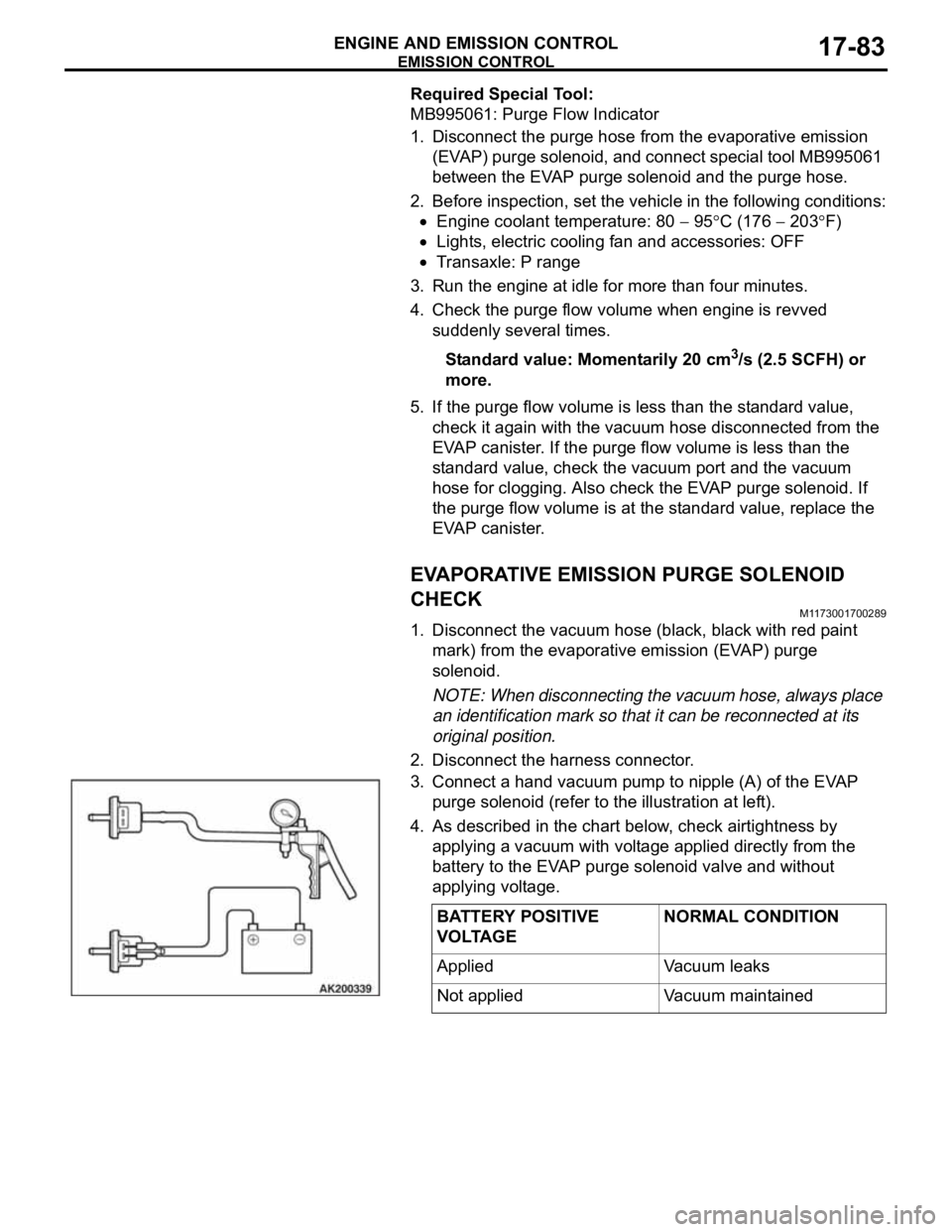
1. Disconnect the vacuum hose (black, black with red paint
mark) from the evaporative emission (EVAP) purge
solenoid.
NOTE: When disconnecting the vacuum hose, always place
an identification mark so that it can be reconnected at its
original position.
2. Disconnect the harness connector.
3. Connect a hand vacuum pump to nipple (A) of the EVAP
purge solenoid (refer to the illustration at left).
4. As described in the chart below, check airtightness by
applying a vacuum with voltage applied directly from the
battery to the EVAP purge solenoid valve and without
applying voltage.
BATTERY POSITIVE
VOLTAGENORMAL CONDITION
Applied Vacuum leaks
Not applied Vacuum maintained
Page 1472 of 1500
AUTOMATIC TRANSMISSION DIAGNOSIS
AUTOMATIC TRANSMISSION23A-13
A/T DIAGNOSTIC TROUBLESHOOTING STRATEGYM1231007600339
Use these steps to plan your diagnostic strategy. If
you follow them carefully, you will find most A/T mal-
functions.
1. Gather as much information as possible about the
complaint from the customer.
2. Verify that the condition described by the
customer exists.
3. Check the vehicle for any A/T Diagnostic Trouble
Codes (DTCs).
4. If you can not verify the condition and there are no
DTCs, the malfunction is intermittent. For
information on how to cope with intermittent
malfunctions, refer to GROUP 00, How to Use
Troubleshooting/Inspection Service Points
How
to Cope with Intermittent Malfunction P.00-14.
5. If you can verify the condition but there are no
DTCs, or the system can not communicate with
diagnostic tool, refer to the Symptom Chart
P.23A-35.6. If there is a DTC, record the number of the code,
then erase the code from memory using
diagnostic tool.
7. Reconfirm the symptom with a Road Test.
8. If a DTC is set again, go to the Inspection Chart
for Diagnostic Trouble Codes.
9. If a DTC is not set again, the malfunction is
intermittent. For information on how to cope with
intermittent malfunctions, refer to GROUP 00,
How to Use Troubleshooting/Inspection Service
Points
How to Cope with Intermittent
Malfunction P.00-14.
10.After repairs are completed, conduct a Road Test
duplicating the complaint conditions to confirm the
malfunction has been eliminated.
DIAGNOSTIC FUNCTIONM1231022500135
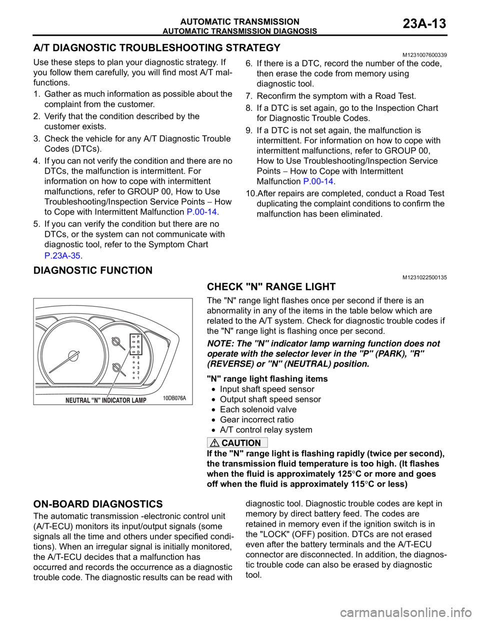
CHECK "N" RANGE LIGHT
The "N" range light flashes once per second if there is an
abnormality in any of the items in the table below which are
related to the A/T system. Check for diagnostic trouble codes if
the "N" range light is flashing once per second.
NOTE: The "N" indicator lamp warning function does not
operate with the selector lever in the "P" (PARK), "R"
(REVERSE) or "N" (NEUTRAL) position.
"N" range light flashing items
Input shaft speed sensor
Output shaft speed sensor
Each solenoid valve
Gear incorrect ratio
A/T control relay system
If the "N" range light is flashing rapidly (twice per second),
the transmission fluid temperature is too high. (It flashes
when the fluid is approximately 125
C or more and goes
off when the fluid is approximately 115
C or less)
ON-BOARD DIAGNOSTICS
The automatic transmission -electronic control unit
(A/T-ECU) monitors its input/output signals (some
signals all the time and others under specified condi-
tions). When an irregular signal is initially monitored,
the A/T-ECU decides that a malfunction has
occurred and records the occurrence as a diagnostic
trouble code. The diagnostic results can be read with diagnostic tool. Diagnostic trouble codes are kept in
memory by direct battery feed. The codes are
retained in memory even if the ignition switch is in
the "LOCK" (OFF) position. DTCs are not erased
even after the battery terminals and the A/T-ECU
connector are disconnected. In addition, the diagnos-
tic trouble code can also be erased by diagnostic
tool.